Injection Molding Tolerances: The DFM Guide
Chasing the tightest possible number on a drawing is usually the wrong instinct. In injection molding, the part that wins is the one that fits the assembly, survives the process, and can be reliably repeated in production. A beautifully tight linear callout that ignores shrinkage, tool behavior, and stack-up just gives you scrap with a nicer label.
The right question is not, “Can the mold hold a microscopic number?” It's, “Which dimensions control function, which ones only consume budget, and which geometric controls keep the assembly working when real plastic cools, moves, and varies?”
Table of Contents
Standard Tolerance Grades and Dimensional Scaling- How the tolerance bands scale
Material Shrinkage and Resin Selection Impacts- Shrinkage sets the starting point
Geometry, Tooling, and Process Control Variables- Tool rigidity and part geometry work together
DFM Rules for Specifying Tolerances on Drawings- What to tighten and what to leave alone
The True Cost of Tightening Tolerance Requirements- Where the cost shows up
Inspection Methods and Measurement Best Practices- Match the measurement to the assembly state
Rethinking Precision in Plastic Part Design
A machined-part mindset is a quick route to over-specification. A molded part starts hot, under pressure, and already dealing with shrinkage before it reaches room temperature. Injection molding tolerances have to follow that reality, not a clean CAD assumption.
Modern practice is anchored by ISO 20457:2018, which replaced older regional guidance such as DIN 16901 from 1982. That change matters because the industry moved from six tolerance groups to nine tolerance grades, and it added geometric and positional control instead of treating size as the only variable. The Moldflow overview of tolerance standards shows that shift clearly, and it matches what designers see on real drawings.
Functional fit beats universal tightness
A blanket callout on every dimension usually creates cost without improving fit. The better approach is to identify the features that drive assembly, sealing, snap retention, or alignment, then let the rest live inside a commercial tolerance band. On a housing, that usually means the boss pattern, datum faces, and connector interfaces deserve tighter attention, while cosmetic walls can remain looser so they mold cleanly.
Practical rule: if a dimension does not affect assembly, sealing, or motion, it usually does not deserve a precision callout.
That choice lowers tooling risk and shortens the discussion with the molder. It also avoids a familiar mistake, treating every dimension like a bearing journal. Plastics do not reward that habit.
A better design review starts with function, then works backward to tolerance intent. A snap-fit tongue, a seal land, and a decorative wall behave very differently in the tool, even when they sit on the same CAD model. One should be controlled tightly, one should be checked against the mating part, and one should often be left to standard commercial variation.
Assembly-level stack-up is the true test. A part can miss a few linear targets and still work, while a perfectly tight single feature can still fail if datum relations, warpage, or mating geometry are ignored. That is where over-tolerancing turns into scrap, rework, and arguments over drawings that should have been resolved at the interface level.
Standard Tolerance Grades and Dimensional Scaling
Injection molding tolerances must scale with feature size. As dimensions grow, shrinkage, thermal movement, and flow variation create a wider practical window. A single tolerance number across an entire drawing usually misrepresents what the process can hold.
Published standards and shop-floor guides use graded bands for that reason. Commercial production commonly works around ±0.1 mm to ±0.2 mm for engineered plastic parts, while smaller or more demanding features may use ±0.05 mm to ±0.08 mm. The relevant decision is not whether the tightest grade is available. It is whether the feature's function justifies the added process control and inspection.
How the tolerance bands scale
| Nominal Dimension Range | Standard Commercial Tolerance | Precision / Fine Tolerance |
|---|---|---|
| Under 0.125 in | ±0.010 in | ±0.05 mm to ±0.08 mm for small features |
| 0.125 to 0.500 in | ±0.020 in | ±0.05 mm to ±0.08 mm for small features |
| 0.500 to 1.00 in | ±0.030 in | ±0.025 mm for precision medical applications |
| 7 to 10 in | up to ±0.125 in | , |
These bands reflect how manufacturing standards are applied feature by feature rather than as one universal requirement. A commercial manufacturing guide places standard injection-molded tolerances around ±0.125 mm and cites precision medical parts at roughly ±0.025 mm. Xometry's manufacturing standards reference illustrates the trade-off: the application may demand tighter control, while larger dimensions still require more allowance.
A practical rule of thumb for standard molding is about ±0.1 mm on small features, increasing to roughly ±0.2 mm at 25 to 50 mm, ±0.35 mm at 50 to 100 mm, and about ±0.5 mm above 100 mm. The OpenSpindle tolerance chart also gives a percentage-based guide for larger parts, about 0.5% for commercial parts and 0.2% for fine or precision parts. On a 200 mm feature, 0.5% already implies about ±1.0 mm, far beyond a machinist-style expectation.
Read the drawing like a process map
Review the tolerance at the assembly level. Check the accumulated variation between datums, mating features, seals, and moving parts before tightening an individual dimension. A boss location may need control because it determines screw alignment, while an exterior wall may only need to meet a cosmetic and fit requirement.
Small, supported features can sometimes justify a fine grade. Large unsupported spans, thin walls, and features affected by warpage generally need more room. Use geometric controls and functional datums where relationships matter, rather than filling the drawing with narrow linear limits.
A tolerance that does not improve fit, sealing, alignment, or motion only adds inspection and scrap risk. The drawing should spend precision on the interfaces that make the assembly work.
Material Shrinkage and Resin Selection Impacts
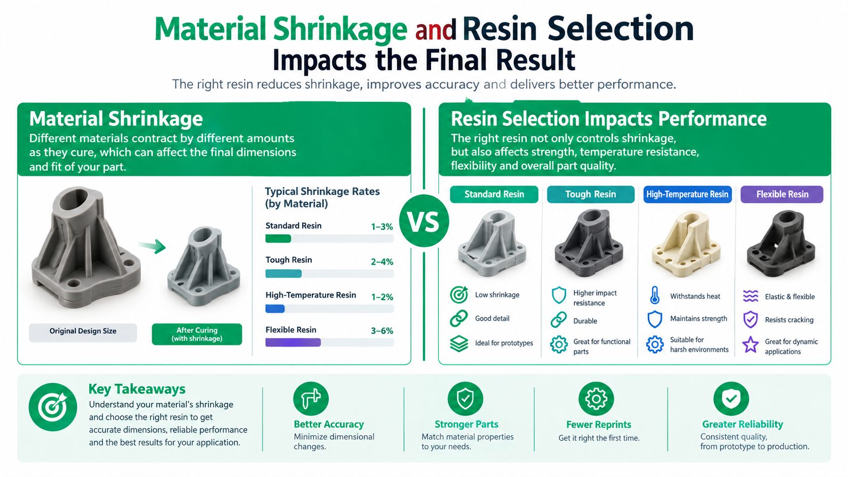
Material choice often decides the tolerance ceiling before tool steel is even ordered. Resins don't shrink the same way, and they don't stay equally stable after molding. That's why a tight tolerance request can be realistic in one polymer and reckless in another.
Shrinkage sets the starting point
The shrinkage ranges in common engineering materials vary a lot. Verified guidance lists ABS at about 0.7 to 1.6%, PC/ABS at about 0.5 to 0.7%, POM at about 1.8 to 2.5%, PP homopolymer at about 1 to 3%, and rigid PVC at about 0.1 to 0.6%. Boyan Manufacturing's tolerance guidance connects those ranges directly to dimensional capability, especially where shrinkage is higher and less predictable.
The practical takeaway is simple. Lower-shrink, more stable resins are easier to hold tightly, while higher-shrink semi-crystalline materials need more tolerance headroom and more careful gate and cooling design. A sub-0.05 mm target on a high-shrink resin is not a normal request. It's a process challenge that may need a different material, a different feature strategy, or a secondary operation.
Filled resins help, but they don't erase physics
Glass-filled grades reduce shrinkage and improve directional stability, which is why they're often used for tighter functional parts. The trade-off is anisotropy if fiber orientation isn't controlled, so the part can still move differently along and across flow. That's useful on a ribbed bracket, less useful on a round bearing seat where concentricity matters.
The right material decision usually happens early, alongside wall thickness and gate placement. A resin that looks attractive on mechanical properties alone can still be a poor tolerance choice if it absorbs moisture, warps, or varies too much during cooling. Teams should evaluate candidate resins against both function and dimensional stability, not just strength or cost. FIRMFG's thermoplastics overview is one reference point for teams comparing materials before lock-in.
Tight tolerance requests make more sense after the resin is chosen, not before.
That order saves time. It also stops teams from forcing a precision target onto a material that was never going to cooperate.
Geometry, Tooling, and Process Control Variables
A well-cut mold still can't rescue a bad geometry. Wall thickness variation, uneven ribs, long flow paths, and poor gate placement all push the part toward different cooling behavior, then different shrink behavior, then different measured dimensions. The mold is part of the answer, but it's not the whole answer.
Tool rigidity and part geometry work together
A valuable point from the technical literature is that mold compliance can create measurable misalignment on the order of 7 to 12 µm in precision systems. That's small in absolute terms, but it's large enough to matter when the assembly is tight and the features are small. The study behind that observation is a reminder that steel is not perfectly rigid under load, even when the machine settings look stable on paper. The DTU paper on mold compliance is one of the few sources that brings that nuance into plain view.
Part design can help or hurt here. Uniform walls and smooth transitions cool more evenly, so they're easier to hold. Thick sections, sharp mass changes, and unbalanced gating create localized shrinkage that shows up as warpage, ovality, or position drift.
Stable processing is part of dimensional control
Process control matters because the same mold can still produce different parts if temperature, pressure, and hold conditions wander. Tight process windows, scientific molding, and cavity pressure monitoring keep the process repeatable over time. That repeatability matters more than machine brand names or theoretical clamp tonnage.
The important shift is to think of tolerance as a system output. Geometry, mold design, and process control all contribute, so the design team should avoid blaming a single variable when dimensions drift. If a feature is important, keep it short, symmetrical, and well-supported. If it isn't, don't force the mold to spend control effort on it.
DFM Rules for Specifying Tolerances on Drawings
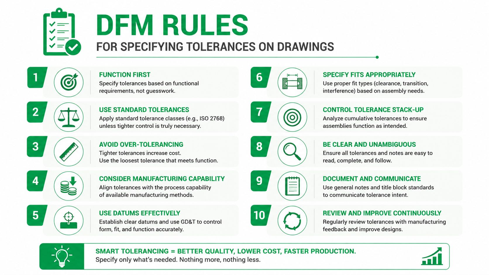
A drawing can create avoidable scrap faster than a bad mold can. Over-constrained dimensions, missing datums, and loose interpretation of mating relationships all push the supplier toward guesswork. Good DFM makes the intended function obvious and leaves the rest of the part manufacturable.
What to tighten and what to leave alone
Critical datums deserve the strictest attention. So do seal lands, snap interfaces, insert locations, and any face that controls assembly alignment. Cosmetic walls, general housings, and clearance zones usually do not.
A simple review pass works well:
- Identify the functional chain: mark only the dimensions that affect fit, motion, or sealing.
- Choose the right control type: use GD&T when flatness, perpendicularity, concentricity, or true position matters more than a simple plus/minus limit.
- Isolate the critical datum scheme: make sure the drawing reflects how the part is located in assembly, not just how it sits in CAD.
- Leave non-critical dimensions commercial: don't force precision where the part won't use it.
- Check mating parts together: tolerance decisions should make sense across the full stack, not in isolation.
A good mold shop can usually build to a clear functional drawing faster than to a vague “make it tight everywhere” request.
That's also where an internal review with FIRMFG's DFM guidance for injection molding can be useful, especially if the part combines inserts, clips, and cosmetic surfaces in one design. The goal is not to make every feature identical in strictness. It's to put the right controls on the right features.
Geometric controls often beat tighter linear numbers
Flatness, perpendicularity, and true position often matter more than a lone linear tolerance because assemblies locate on planes and relationships, not just lengths. A part can be “in tolerance” on paper and still fail to seat correctly if the faces are out of plane or the holes wander relative to the datum. That's why GD&T is often the better engineering language for molded parts.
If you treat every line item as a machining tolerance, the print gets expensive and less useful. If you treat the drawing as an assembly contract, the tolerances become clearer and usually easier to hold.
The True Cost of Tightening Tolerance Requirements
Every tighter decimal point adds cost somewhere in the system. The tool gets harder to build, the process window narrows, inspection becomes more involved, and scrap risk rises. The print may look cleaner, but the factory often pays for that polish.
Where the cost shows up
Tighter tolerances can push a program toward better steel, finer cavity finishing, and more careful tooling balance. They can also cut cavity count, because tighter control leaves less room for variation between shots and between cavities. The schedule feels it too, since more development time and more process validation are usually needed before release.
Inspection burden grows alongside that pressure. Hand gauges may no longer be enough, so teams rely more on CMMs, fixtures, and structured sampling. That is sensible when the feature drives fit or function. It is wasteful when the part was over-specified from the start. FIRMFG's injection molding cost guide makes the same practical point from a cost perspective.
Tighter isn't always lower risk
Tighter tolerances often sound safer, but they can raise risk when the design does not need that level of control. A looser, function-based tolerance with the right datum scheme usually gives better yield and fewer late changes than a blanket precision callout.
The source material on tolerance strategy makes the point plainly. Standard molded parts often sit around ±0.1 to 0.2 mm, while precision classes around ±0.05 mm or tighter need premium tooling, controlled materials, and validated conditions. IMTEC's tolerance guide also highlights the tradeoff between process burden and functional gain. That is the core decision, not whether a number looks sharp on the title block.
If a feature needs a tighter window, tie it to function. If you cannot explain the functional gain, the tolerance is probably too tight. That discipline protects lead time, scrap rate, and launch risk at the same time.
Inspection Methods and Measurement Best Practices
A tolerance isn't real until someone can measure it the same way every time. That sounds obvious, but molded parts are often checked in a way that distorts them, clamps them wrong, or ignores the state they will see in assembly. The result is a drawing that says one thing and a measurement process that says another.
Match the measurement to the assembly state
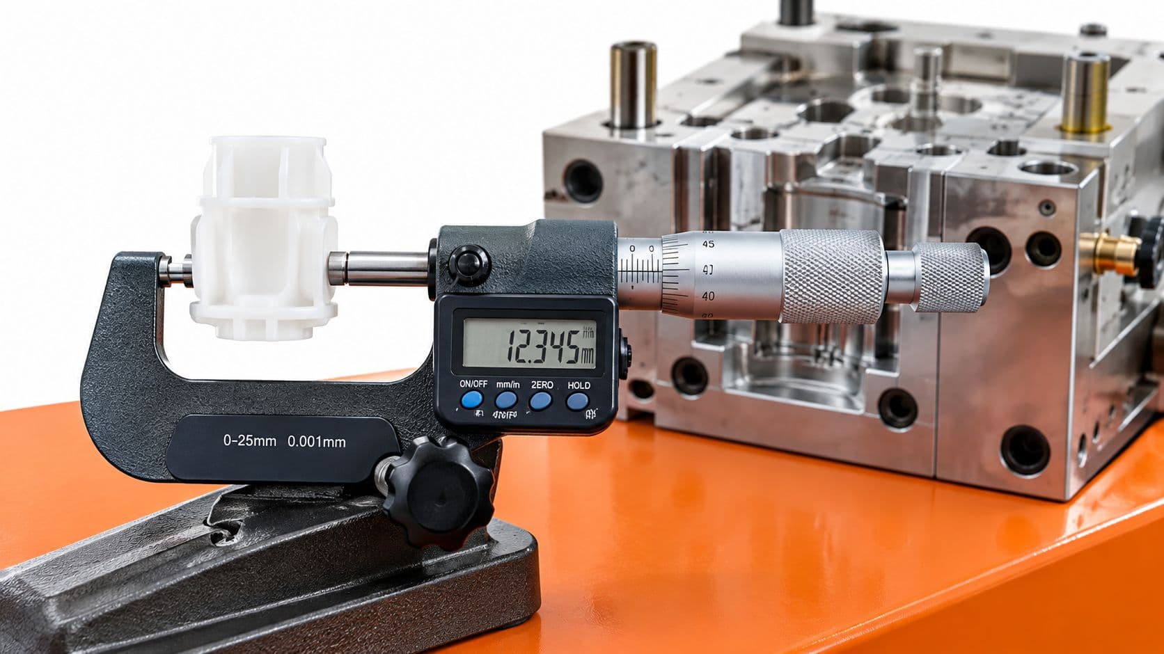
Basic tools still matter. Calipers and micrometers are fine for many features, but they won't tell you much about true geometry if the part is flexible or the datum scheme is sensitive. For more critical work, CMMs and 3D scanning are better because they can map relationships across the full feature set.
The bigger issue is fixturing. If a part is measured in a way that bends it, the result is artificial error. The fixture should mimic the assembly state as closely as possible, especially for seals, snaps, and insert-molded regions where shape under load matters.
Use first article inspection to lock the process
First article inspection should confirm that the molded part matches the drawing under the agreed measurement conditions. That includes temperature condition, fixturing, and the actual feature order being checked. If the part isn't stabilized before inspection, the numbers can drift even though the process itself is fine.
A solid production routine usually follows three habits:
- Establish the inspection condition: define when the part is measured after molding and under what environment.
- Use the right gauge for the feature: don't force calipers onto a geometry that needs a CMM or a fixture.
- Sample for drift, not just pass/fail: a part can pass early and drift later if packing, temperature, or material moisture changes.
Measure the part the way the customer will use it, not the way the gauge is easiest to apply.
That mindset closes a lot of quality disputes before they start. It also keeps production aligned with function instead of with a measurement artifact.
If you need help turning a CAD model into a moldable, measurable part, FIRMFG supports DFM review, rapid tooling, and low-volume injection molding with tolerance feedback before production. Their team can help you separate critical datums from over-specified features so the drawing matches what the process can actually hold.