Geometric Tolerance Straightness: A Practical Guide
A drawing lands on your desk with a straightness callout that looks reassuringly precise: 0.05 mm on a milled edge. The designer expects it to stop wobble, guarantee contact, and keep the bracket aligned. Inspection then reports a failure, or worse, passes the part while the assembled product still rocks because the callout controlled a line element, not the complete surface shape.
That situation is common because the geometric tolerance straightness symbol stays the same while its meaning changes with attachment. A frame pointing to a surface controls surface straightness. A frame associated with a diameter controls the derived axis inside a cylindrical zone. The right interpretation also depends on feature length, datums, material condition, fixturing, and the measurement method.
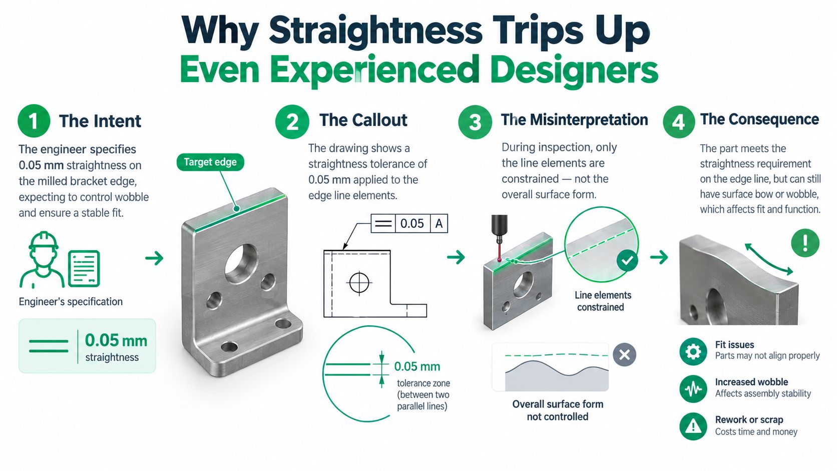
Table of Contents
Straightness as a Form Control Under ASME Y14.5 and ISO 1101
Surface Straightness Versus Axis Straightness- Match the callout to the failure mode
How Straightness Values Scale With Feature Length- Use a scale-based decision
Inspection Methods That Actually Verify Straightness- Choose the method by feature type
Applying Straightness to CNC, 3D Printing, and Molding- CNC machining
Common Straightness Pitfalls and How to Avoid Them- Review the callout, not just the number
A Practical Checklist Before You Release the Drawing- Run these checks in order
Why Straightness Trips Up Even Experienced Designers
The first question in drawing review should be simple: what must remain straight for the part to work? If the answer is a visible or functional line on a face, surface straightness may be appropriate. If the answer is the centerline of a shaft, pin, or bore, the drawing needs axis straightness. Confusing those two controls creates a technically correct inspection of the wrong characteristic.
Straightness is a form control, so it evaluates a feature relative to its own ideal geometry rather than orienting it to a datum. That makes it useful, but limited. It doesn't establish where a feature sits in space, and it doesn't automatically control the complete shape of a broad planar surface. A surface can satisfy straightness in one direction while still being warped across another direction.
Start with design intent
Before choosing a value, write the failure mode in ordinary language:
- Sliding contact: a bowed guide edge can create uneven clearance along travel.
- Sealing: a local crest or valley can interrupt contact along a seal line.
- Centerline assembly: a bowed shaft or pin can bind inside a mating bore.
- Overall plane control: the entire face needs flatness, not merely straightness along selected lines.
- Orientation: the feature must relate to a datum, which points toward parallelism, perpendicularity, or profile.
A callout of 0.05 mm means the inspected line must remain within a tolerance zone 0.05 mm wide, as described in this straightness GD&T reference. That number only becomes meaningful after you identify the controlled line, its length, and the inspection setup.
Practical rule: Never approve a straightness value until you can name the exact failure it prevents and the exact measurement that will prove it.
Long, thin parts deserve extra skepticism. Their own weight can influence the setup, and machining forces, residual stress, temperature, and support points can alter the observed result. A tight callout may therefore be unrealistic not because the machine is incapable, but because the drawing ignores how the part is held and measured.
Straightness as a Form Control Under ASME Y14.5 and ISO 1101
A shaft can meet its size limits and still bow enough to bind in a mating bore. A rail can look flat overall yet have a contact edge that rises and falls along its length. Straightness controls the form of the feature itself, so the right callout depends on which failure the part must avoid and how inspection will prove compliance.
Under ASME Y14.5, straightness is one of the 14 main geometric characteristics and belongs to the form category. Its symbol is a single horizontal line. Straightness does not use a datum, because it controls the feature's own form rather than its orientation or location relative to another feature. The standard has guided North American drawing practice since its first release in 1982, with later revisions retaining straightness as a core manufacturing control.
For a surface line element, the tolerance zone consists of two parallel lines separated by the specified value. Every evaluated line element in the indicated direction must fit within that zone. This callout suits a defined contact path, such as a sealing edge, guide surface, or sliding track. It does not control the complete face as a single plane. If the entire surface must remain within two parallel planes, flatness may be the better choice.
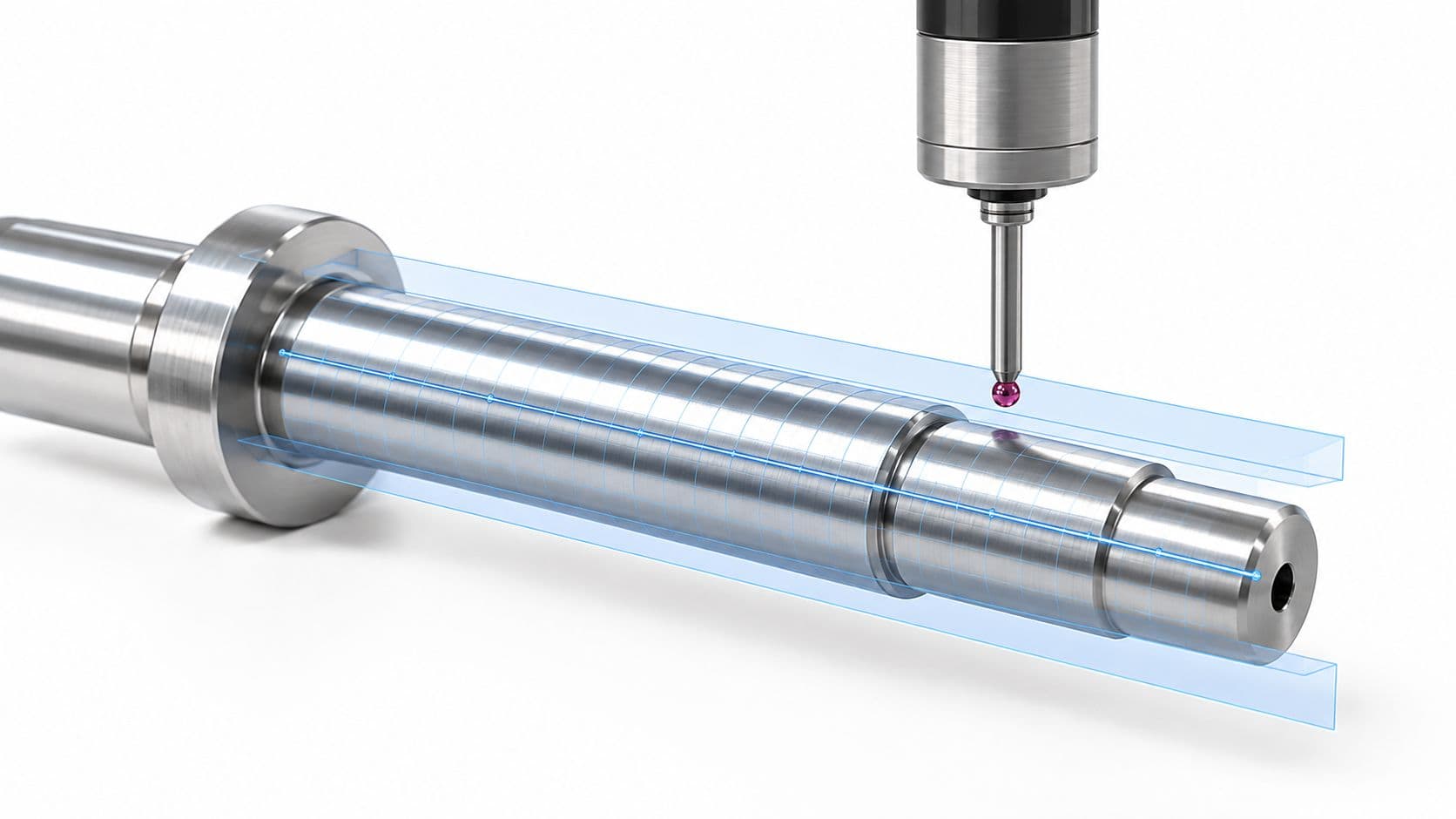
Applied to a feature of size, axis straightness uses a cylindrical tolerance zone. The feature control frame is associated with the size dimension, and the diameter symbol before the tolerance identifies that cylindrical zone. The derived median line must remain inside it. A 20 mm ground shaft, for example, may satisfy its diameter limits while failing axis straightness if its centerline bows beyond the permitted path. Inspection must therefore evaluate the derived axis, not only the outside surface.
ISO 1101 expresses the same basic idea through internationally recognized drawing language. It permits a straightness zone formed by two parallel lines for a line element or a cylinder for an axis, although symbol conventions and detailed interpretation can differ from ASME practice. State the governing standard on drawings shared across regions and suppliers. Do not assume that a familiar symbol carries every rule unchanged.
A 600 mm linear rail illustrates the surface case. If the callout points to its top surface, the concern may be the behavior of each longitudinal line element where a carriage contacts the rail. The rail's relation to another datum is a separate question, potentially requiring orientation or location control.
Section 3 provides the full surface-versus-axis comparison. For a broader explanation of drawing interpretation, use this practical GD&T guide. Read the feature attachment first, identify the tolerance-zone shape, then confirm that the control matches the functional failure and the planned inspection method.
Surface Straightness Versus Axis Straightness
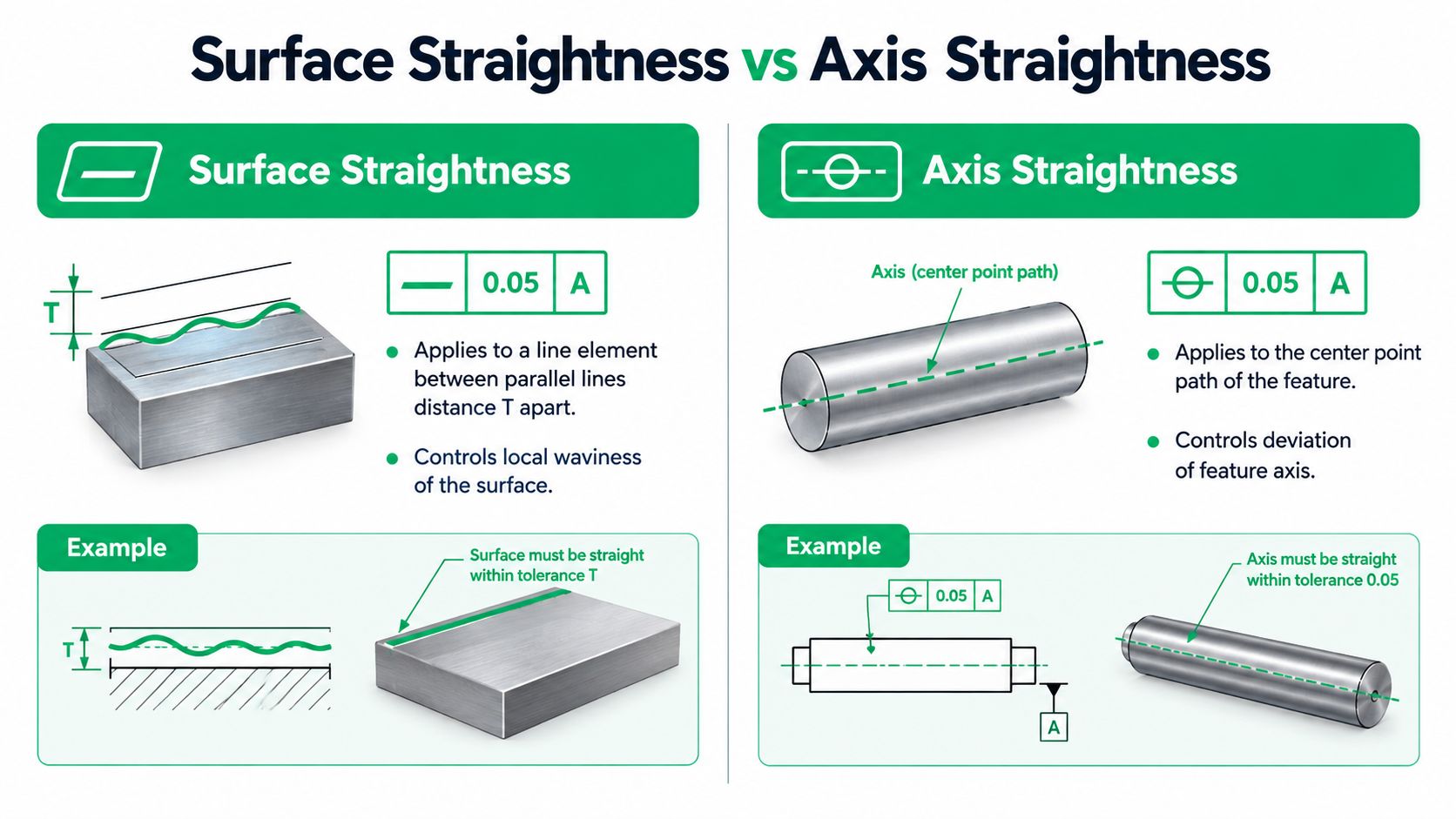
The two controls share a symbol, but they answer different engineering questions. Surface straightness asks whether an individual line element on a surface is straight. Axis straightness asks whether the derived centerline of a feature of size stays within a cylindrical path.
For surface straightness, the tolerance zone is formed by two parallel lines, or the corresponding parallel planes for the surface interpretation, separated by T. The frame points to the controlled surface or its extension. This is suitable when a particular line of contact matters, such as a sealing edge, guide rail, sliding track, or datum edge whose local bow affects function.
Axis straightness is attached to a diameter dimension. The diameter symbol before T indicates a cylindrical tolerance zone. The derived median line must remain within that cylinder, which limits bow and changes in the centerline path. The outside surface can still contain local form variation that must be handled by size, circularity, cylindricity, or another applicable control.
Match the callout to the failure mode
| Design intent | Appropriate control | What it limits | Typical inspection concern |
|---|---|---|---|
| A rail face must maintain consistent local contact | Surface straightness | Line-element bow in the indicated direction | Stylus or indicator trace along the contact line |
| A seal lands along a narrow edge | Surface straightness | Local crest and valley along that edge | Support must not distort the face |
| A shaft must pass through a close-fitting bore | Axis straightness | Derived median-line deviation | Cross-section sampling and axis calculation |
| A pin must remain centered through engagement | Axis straightness | Centerline bow over feature length | CMM or a validated functional method |
| A complete plane must remain within one plane | Flatness, not straightness | Overall planar form | Surface-based evaluation across the face |
The distinction is especially important on cylindrical parts. A surface straightness callout can control a generatrix, but it doesn't directly constrain the axis. Conversely, axis straightness doesn't promise that every visible surface line is straight. If the mating condition depends on both, specify and inspect the separate requirements rather than expecting one symbol to do both jobs.
No datum belongs in a basic straightness frame. If the requirement needs a datum relationship, you're probably describing orientation or profile rather than pure form. That change should be deliberate because it changes both design intent and inspection logic.
How Straightness Values Scale With Feature Length
A straightness value has no useful meaning without the length over which it applies. A short pin and a long rail don't experience the same manufacturing difficulty, even when both are made from similar material and assigned the same nominal tolerance.
ISO-based guidance illustrates this scale effect directly. For nominal lengths up to 10 mm, some straightness and flatness classes can be as tight as 0.02 mm. Over 1000 mm, the same class can allow up to 0.4 mm, and some classes reach 1.6 mm over 3000 mm, as reported in this ISO 1101 tolerance guidance. These values aren't a universal drawing prescription. They show why straightness is a family of size-based controls rather than one fixed limit.
A 20 mm dowel pin may justify a tight absolute value because its short span is easier to support and inspect. Applying the same 0.05 mm value to a 1.2 m linear rail without checking function, stiffness, support, thermal state, and process capability is poor specification practice. The rail may need a straightness requirement, but the value should reflect its working length and the carriage's actual sensitivity to deviation.
Use a scale-based decision
ISO guidance provides classes and length ranges that help establish a starting point. ASME Y14.5 gives the designer more responsibility to define the requirement rather than prescribing one universal length-scaling table. In either system, the drawing should connect the value to the functional span.
| ISO grade | 100 mm feature | 300 mm feature | 1000 mm feature |
|---|---|---|---|
| IT6 | Use the applicable ISO size-based value | Use the applicable ISO size-based value | Use the applicable ISO size-based value |
| IT7 | Use the applicable ISO size-based value | Use the applicable ISO size-based value | Use the applicable ISO size-based value |
| IT8 | Use the applicable ISO size-based value | Use the applicable ISO size-based value | Use the applicable ISO size-based value |
| IT9 | Use the applicable ISO size-based value | Use the applicable ISO size-based value | Use the applicable ISO size-based value |
| IT10 | Use the applicable ISO size-based value | Use the applicable ISO size-based value | Use the applicable ISO size-based value |
| IT11 | Use the applicable ISO size-based value | Use the applicable ISO size-based value | Use the applicable ISO size-based value |
| IT12 | Use the applicable ISO size-based value | Use the applicable ISO size-based value | Use the applicable ISO size-based value |
The table deliberately points back to the governing ISO table rather than inventing grade values. Straightness isn't interchangeable with a default linear dimension tolerance. A size tolerance controls local size, while straightness controls the path or line form across the specified feature.
The longer the feature, the more aggressively you should challenge an inherited straightness number.
Inspection Methods That Actually Verify Straightness
Inspection must reproduce the characteristic named by the drawing. A dial indicator sweeping the outside of a shaft doesn't automatically verify axis straightness, because the reading can include roundness, surface waviness, setup error, and support effects. A CMM can calculate the derived axis, but only if the probing strategy and datum-free evaluation are defined correctly.
Choose the method by feature type
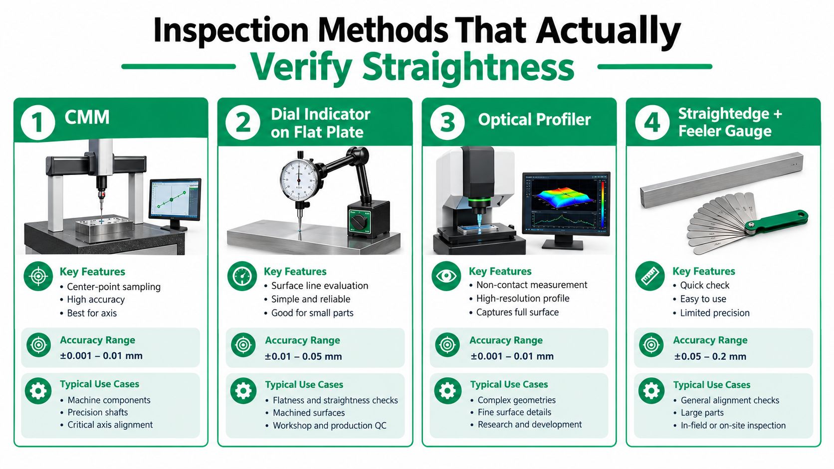
CMM evaluation is the strongest general choice for axis straightness on shafts, pins, and bores. The machine samples multiple cross-sections, determines their centers, constructs the derived median line, and evaluates that line against the cylindrical zone. The CMM inspection service overview is useful when deciding whether the drawing's axis requirement needs coordinate measurement rather than a shop-floor approximation.
A profilometer or optical profiler fits surface straightness where a stylus or optical trace follows the controlled line. A profilometer makes the most sense for a rigid flat or cylindrical surface that can be supported without changing shape. Optical measurement helps when contact force could deflect a thin edge or delicate feature.
An optical comparator or laser scanner provides non-contact data for fragile, narrow, or difficult-to-touch profiles. These systems still need a stable reference, suitable resolution, and a clear extraction method. A dense point cloud doesn't fix an ambiguous definition of which line element or axis the inspector must evaluate.
A dial indicator on a surface plate, straightedge, or V-block setup is useful for a quick process check. It can be economical for surface straightness and for screening shafts, but it doesn't isolate axis straightness as cleanly as a calculated centerline method.
Treat the setup as part of the measurement
Long, thin parts can sag between supports. Clamping can straighten a part during measurement and release it after inspection. Temperature can produce differential expansion, while an indicator's contact pressure can bend a light section. These effects may be larger than the tolerance you're trying to judge.
Before release, specify or agree on:
- Support condition: Define whether the part is free, supported at designated points, or measured in a functional fixture.
- Temperature control: Measure after the part and equipment stabilize in the agreed inspection environment.
- Sampling plan: For axis straightness, sample enough cross-sections to capture bow and kink rather than relying on end points.
- Evaluation rule: State how the software or inspector extracts line elements and derived centers.
- Uncertainty review: Ensure the method can discriminate a pass from a fail instead of reporting setup variation as part error.
The right inspection cost follows the tolerance's functional risk. A loose visual or indicator check may be sensible for a noncritical edge. A tight axis requirement on a precision shaft deserves a measurement plan designed around the cylindrical zone, not a convenient but indirect sweep.
Applying Straightness to CNC, 3D Printing, and Molding
The same symbol behaves differently across processes because each process creates different distortion mechanisms. A drawing that is reasonable for a ground rail may be wasteful or misleading for an FDM prototype.
CNC machining
For CNC work, start with the part's stiffness and the support strategy. Tool deflection, workpiece deflection, residual stress, and thermal movement can all affect a long feature. A single finishing operation may work for a short, rigid edge, while a long shaft may need staged roughing, stable support, stress management, and a dedicated finishing setup.
For a machined rail, a surface straightness callout can be paired with a note identifying the controlled travel direction. For a shaft, attach the axis straightness frame to the diameter dimension and make the inspection method explicit in the quality plan. If the functional requirement is really a relationship to a datum, use an orientation or profile control instead of forcing straightness to carry that job.
Additive manufacturing
Straightness is often the wrong primary control for FDM and SLA parts when layer adhesion, shrinkage, and warping dominate the result. For a printed enclosure wall, profile of a surface, overall size, or a functional fit requirement may communicate the design intent more clearly. Post-machining a critical rail or bore can also separate the printed near-net shape from the final controlled feature.
The process choice itself deserves review, especially when a prototype moves from printed plastic to machined metal. This comparison of CNC machining and 3D printing helps frame where each process fits before a designer copies a machining tolerance onto an additive part.
Injection molding
Molded parts need a different conversation. Draft affects how the feature leaves the mold, ejection can introduce movement, and glass-filled materials can develop direction-dependent shrinkage. A long molded wall may need ribs, balanced wall thickness, controlled gate placement, and a datum scheme that reflects the assembled condition.
In Fusion 360, SolidWorks, or Onshape, create separate feature-control-frame examples for each process rather than hiding all requirements in a generic note:
- CNC example: surface straightness on a machined guide face, with the inspection direction identified.
- Printed example: profile or size requirement on a post-processed interface, with as-printed surfaces treated as noncritical.
- Molded example: profile of a wall or interface, with draft and datum targets documented in the DFM notes.
Common Straightness Pitfalls and How to Avoid Them
Drawing reviews tend to expose the same mistakes because designers often choose the familiar symbol before defining the functional surface. The correction usually isn't a tighter value. It's a different control or a clearer attachment.
Review the callout, not just the number
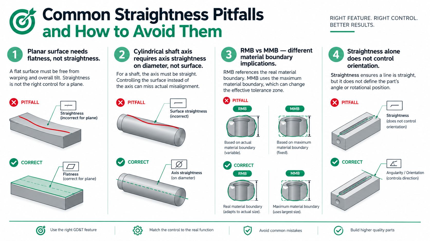
- Planar surface needs flatness: Wrong approach, a straightness frame on a broad face when the entire face must lie in one plane. Correct approach, use flatness because the requirement concerns the complete surface. Reason, straightness evaluates line elements, not the whole plane at once.
- Shaft axis needs centerline control: Wrong approach, surface straightness attached to a cylindrical surface when a mating bore responds to the shaft center. Correct approach, attach axis straightness to the diameter dimension and use the cylindrical zone. Reason, the assembly failure comes from centerline bow.
- Length was ignored: Wrong approach, copy a short-feature value onto a long shaft or rail. Correct approach, scale the tolerance using the governing ISO guidance or a documented functional value for the feature length. Reason, manufacturing and measurement difficulty increase with span.
- Material condition was omitted: Wrong approach, leave out a material condition modifier when assembly depends on the feature's material boundary. Correct approach, evaluate whether MMC, LMC, or another permitted condition is needed under the governing standard. Reason, the modifier can change how size and geometric variation combine.
- Additive warpage was dismissed: Wrong approach, place a machining-level straightness requirement on an as-printed wall without a finishing plan. Correct approach, control the functional interface after machining or use a profile requirement suited to the printed condition. Reason, the print process may not hold the specified form reliably.
If the zone is represented by two parallel lines, you're controlling a line element. If it is cylindrical, you're controlling an axis.
Straightness also doesn't control orientation. A feature can be straight and still point in the wrong direction relative to the assembly. If its orientation matters, connect the requirement to a datum through parallelism, perpendicularity, angularity, or profile as appropriate.
A Practical Checklist Before You Release the Drawing
A release review should follow the way a machinist, inspector, and supplier will read the print. Start with the feature, then the function, then the measurement. Don't begin with a tolerance value copied from another part.
Run these checks in order
- Confirm the geometry: Decide whether the requirement is surface straightness, axis straightness, flatness, cylindricity, profile, or an orientation control. A planar face that must remain globally planar needs more than line-element control.
- Read the attachment: A frame on a surface points to surface straightness. A frame tied to a diameter dimension points to axis straightness. Check whether the indicated direction matches the direction of motion, sealing, or contact.
- Review modifiers: Straightness itself is a form control and doesn't use a datum, but an axis control on a feature of size may interact with material condition rules. Confirm whether no modifier, MMC, LMC, or another applicable condition matches the mating requirement.
- Scale the value: Compare the tolerance with feature length and functional clearance. Use ISO class guidance where applicable, or document the engineering basis for a fixed value under ASME practice.
- Name the inspection method: Identify whether the supplier will use a CMM, profilometer, optical system, indicator setup, or functional gauge. For long parts, document support points and measurement condition so the setup doesn't become an uncontrolled variable.
- Challenge the process: Flag callouts on thin printed walls and molded spans where warpage, draft, ejection, or material orientation may dominate. Decide whether post-processing, a different feature control, or a process change is needed.
Straightness rarely works alone in a mature GD&T scheme. It may protect a line element on a datum surface, support a profile requirement, or limit centerline behavior that later affects runout and assembly. The designer's job is to make those relationships explicit without asking one symbol to control every possible failure.
Before sending the drawing for quote, ask one final question: could an inspector independently reproduce the requirement from the print? If the answer is no, the callout needs clarification, not a smaller number.
FIRMFG supports CNC machining, additive manufacturing, injection molding, and related inspection workflows for prototypes and low-volume parts, with DFM feedback on tolerance and process choices. Send your straightness-critical drawing to FIRMFG for a manufacturability review and quote before committing to production.