Aerospace Precision Machining Guide for Tight Tolerances
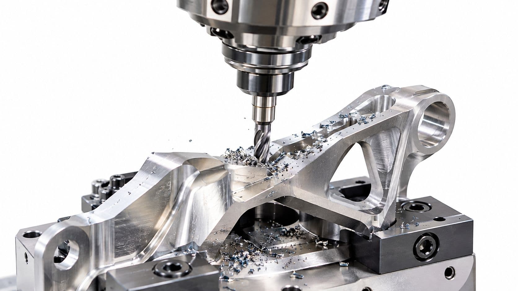
You're reviewing a prototype bracket that should fit an assembly, seal against a mating surface, and survive flight loads. The machine shop says the dimensions are within tolerance, but the first article package is incomplete. One critical feature lacks a clear inspection result, the material certificate isn't tied cleanly to the part, and nobody can explain whether the surface finish was measured before or after deburring. The part may be usable, yet approval stalls.
That situation captures the challenge of aerospace precision machining. The work isn't about removing metal accurately. It's about producing a repeatable part and a defensible record that shows what was made, from which material, with which process, and how each critical requirement was verified.
Table of Contents
How Aerospace Pushed Machining From Manual to Programmable- From hand control to stored instructions
Core Processes Behind Aerospace Precision Machining- Match the process to the problem
Aerospace Alloys and Plastics and How They Change Machining- Aluminum favors speed, but not careless speed
- Titanium exposes process weaknesses
- Nickel alloys, stainless steel, and plastics need different controls
Tolerances Surface Finish and Inspection That Prove Quality- Start with function, then assign control
From DFM to Production Readiness for Aerospace Parts- Step one is a serious DFM review
How to Evaluate an Aerospace Precision Machining Supplier- Start with the technical questions
Introduction to Aerospace Precision Machining Today
Aerospace parts operate inside assemblies where small dimensional errors can affect fit, sealing, clearance, vibration, fatigue behavior, or aerodynamic performance. A turbine component, structural housing, actuator bracket, or landing-gear fitting may require difficult alloys, complex toolpaths, controlled edge conditions, and inspection evidence that supports first article approval.
That's why aerospace machining receives more engineering attention than general-purpose work. The buyer isn't purchasing a shape alone. The buyer is purchasing repeatability, material control, dimensional evidence, and process discipline.
The scale of the sector reflects that importance. One report estimates the U.S. precision machining market at $98 billion in 2022, with automotive and aerospace together driving 45% of total revenue. Another estimate places the global aerospace precision machining market at $45 billion by 2027. These figures are reported in the high-precision CNC machining market analysis, and they show why aerospace remains a high-value demand center rather than a narrow specialist niche.
What the work includes
Aerospace precision machining can involve:
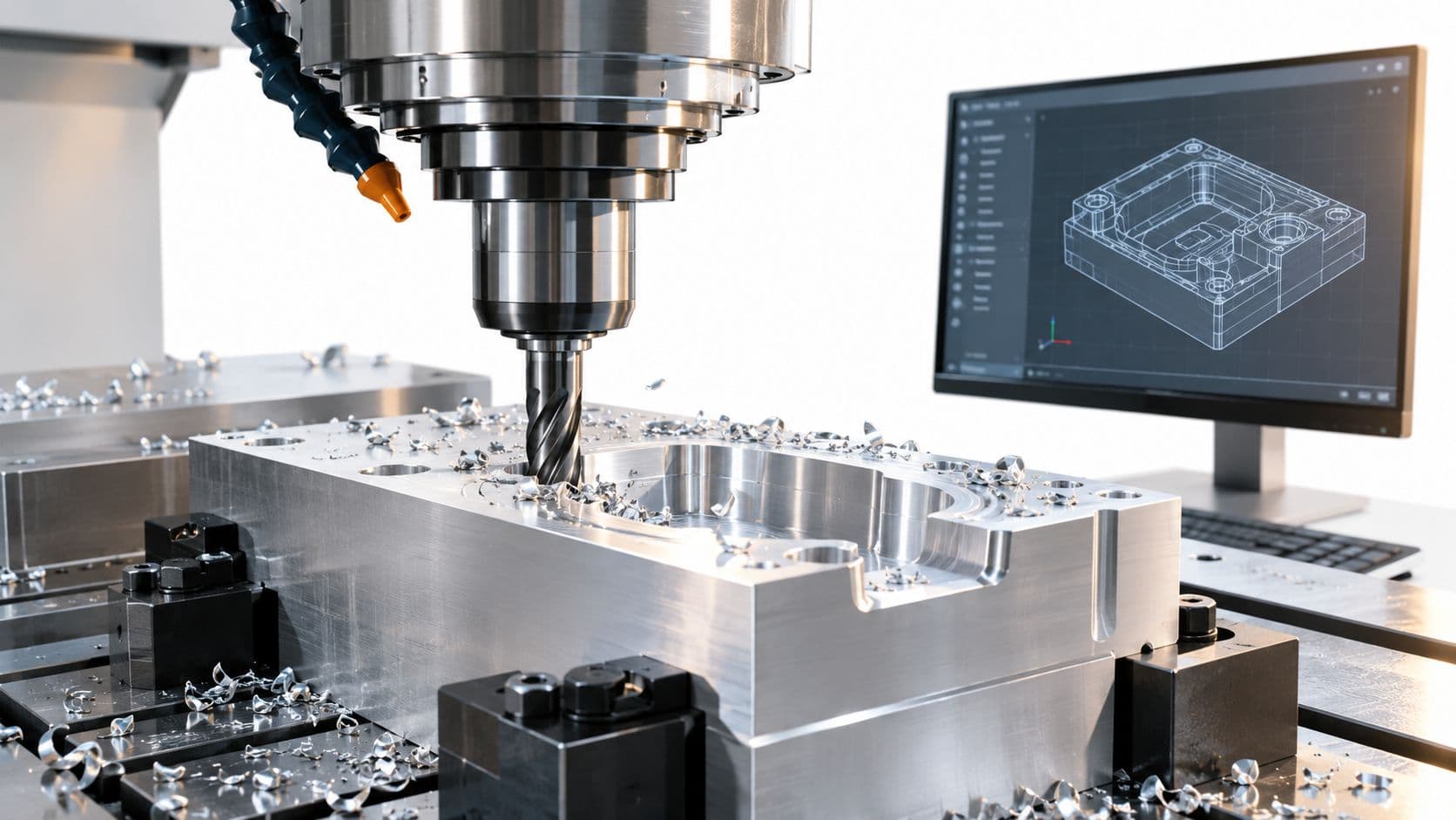
- Multi-axis CNC milling and turning, used for structural parts, housings, contours, and rotational features.
- Wire EDM, useful for hard materials, narrow slots, intricate profiles, and features that are difficult to reach with conventional cutting tools.
- Secondary finishing, including deburring, surface treatment, grinding, polishing, or other operations that protect surface integrity.
- Metrology and documentation, including coordinate measuring machine inspection, surface-finish checks, material records, and first article reporting.
The correct process depends on the part's geometry, material, datum structure, tolerance scheme, and production stage. A prototype may need flexibility and fast feedback. A pilot run needs a stable process that can be repeated. A production program needs records that remain understandable months or years later.
Practical rule: A part that passes inspection once isn't automatically a production-ready part. The supplier must show that the process can produce the same result again.
This guide builds that judgment step by step. It starts with why aerospace pushed machining toward programmable control, then examines process selection, materials, tolerances, inspection, design for manufacturing, and supplier evaluation. The central idea is simple: tight tolerances matter, but repeatable documentation and process control often decide whether a low-volume aerospace program moves forward.
How Aerospace Pushed Machining From Manual to Programmable
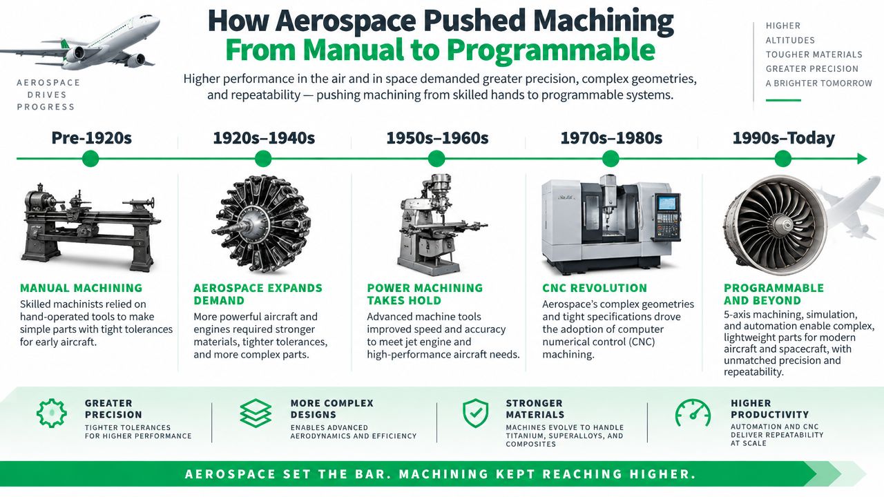
Before numerical control, machinists depended heavily on manual skill, physical templates, fixtures, and repeated adjustments. That approach could produce excellent work, but complex aircraft geometry created a difficult question: how do you make the next part match the first part when the shape includes compound curves, thin sections, and demanding positional relationships?
Aerospace helped answer that question. In 1949, the U.S. Air Force contracted MIT to automate machining for complex airframe components such as rotor blades and wing skins. John Parsons led the effort, which MIT's Servomechanisms Laboratory refined. The work produced the first numerically controlled milling machine in 1952, a milestone described in this history of precision machining.
From hand control to stored instructions
A useful analogy is the difference between hand-drawing a shape and sending the same shape through a controlled plotter.
With hand drawing, the operator can be highly skilled, but results depend on technique, fatigue, setup, and interpretation. A plotter follows stored coordinates and motion commands. If the material, machine condition, tooling, and setup remain controlled, the output becomes easier to repeat.
CNC applies that principle to cutting:
- The designer defines the geometry in a CAD model and drawing.
- The programmer converts geometry into toolpaths that specify motion, cutting conditions, and sequencing.
- The machine executes those instructions through controlled axis movement.
- The inspection team verifies the result against the drawing and approved requirements.
- The organization retains the record, so future parts can be compared with the original evidence.
Programmable machining didn't eliminate the need for skilled people. It changed where their judgment mattered. Engineers and machinists now focus on fixture design, tool selection, thermal behavior, cutter engagement, probing, inspection strategy, and corrective action.
Why the historical shift still matters
Aircraft geometries demanded consistency that manual methods couldn't reliably deliver at scale. That pressure helped create the multi-axis CNC ecosystem now used for turbine components, structural brackets, housings, and other precision parts.
The same logic applies to today's supplier decisions. A machine's number of axes is only one capability. The more important question is whether the supplier can control the complete chain from digital model to fixture, program, inspection, and retained documentation. Aerospace manufacturing remains concentrated in advanced industrial markets where quality, traceability, and dimensional repeatability support safety-critical hardware.
Core Processes Behind Aerospace Precision Machining
Process selection starts with the part, not the machine brochure. A complex titanium housing may need multi-axis milling, probing, controlled fixturing, deburring, and CMM inspection. A thin slot in a hardened alloy may be better suited to wire EDM after a conventional operation establishes the surrounding geometry.
Match the process to the problem
Multi-axis CNC milling handles complex prismatic forms, pockets, curved surfaces, and angled features. Five-axis movement can reduce repositioning and help keep a feature in a more favorable cutting orientation. It also introduces programming, verification, collision-avoidance, and fixturing demands. Engineers evaluating this route can review the practical capabilities described in this guide to 5-axis CNC milling.
CNC turning is the natural choice for shafts, sleeves, bushings, and rotational bodies. Live tooling can add milling operations, but the supplier still needs to manage concentricity, runout, chucking distortion, and the relationship between turned and milled datums.
Wire EDM removes material with an electrically controlled wire rather than a rotating cutter. It suits conductive hard alloys, narrow slots, intricate profiles, and delicate internal features. Its limitation is that it generally requires a prepared workpiece and conductive material, so it often appears as one stage in a wider process stack.
Finishing and edge treatment protect the final part from burrs, sharp transitions, contamination, and inconsistent surface conditions. These operations may happen inside the primary shop or through a qualified partner, but the handoff must preserve part identity and inspection traceability.
| Process | Best For | Key Limitation | Typical Aerospace Use |
|---|---|---|---|
| Multi-axis CNC milling | Complex surfaces, pockets, angled features | Programming and fixturing complexity | Brackets, housings, structural components |
| CNC turning | Round parts and concentric features | Less suitable for non-rotational geometry | Bushings, sleeves, shafts, fittings |
| Wire EDM | Hard conductive alloys and fine profiles | Requires conductive material and prepared access | Slots, inserts, intricate profiles |
| Deburring and finishing | Edge control and surface integrity | Adds coordination and inspection needs | Sealing edges, assembly interfaces, cosmetic and functional surfaces |
| CMM and metrology | Dimensional verification | Measurement strategy must match datums | First articles, critical features, batch verification |
For short runs, coordination often matters more than theoretical cutting speed. Every outside handoff creates another opportunity for delays, mixed revision levels, or incomplete records. A supplier that can coordinate machining, finishing, and inspection under one controlled workflow may reduce that risk, provided it can show how records follow the part.
Aerospace Alloys and Plastics and How They Change Machining
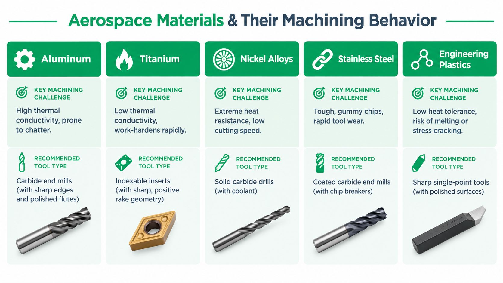
Material selection changes the machining plan before the first tool touches the workpiece. Aluminum may remove quickly and conduct heat away from the cutting zone, while titanium retains heat near the tool and can accelerate wear. Nickel alloys preserve strength at high temperature, which is valuable in service and demanding during cutting.
Aluminum favors speed, but not careless speed
Aluminum alloys are common where low weight, corrosion resistance, and useful strength-to-weight performance matter. They're generally machinable, but thin walls and deep pockets can still deflect, chatter, or distort. A sharp tool, controlled chip evacuation, suitable coolant strategy, and stable fixturing remain important.
For engineers specifying aluminum parts, the aluminum CNC machining service should be evaluated against the actual geometry, alloy, wall thickness, and finish requirement, not just the material name. Two aluminum parts can have very different risk profiles if one has thick, sturdy walls and the other contains flexible webs or long unsupported surfaces.
Titanium exposes process weaknesses
Titanium's lower machinability creates higher heat, faster tool wear, and longer cutting cycles. A benchmark review cited an aluminum version of a component requiring nominally 14 minutes, while the same geometry in titanium can take substantially longer because of the alloy's cutting behavior, as discussed in this review of titanium machining.
That contrast affects quoting and scheduling. The supplier may need slower cutting parameters, sharper tooling, more conservative engagement, and tighter monitoring for chatter, burrs, and dimensional drift. A low unit quantity doesn't remove those setup and process-development requirements.
Nickel alloys, stainless steel, and plastics need different controls
Nickel alloys tolerate extreme temperatures in service, but that resistance also makes heat removal and tool life difficult during cutting. Stainless steels can produce gummy chips and work-hardened zones. Engineering plastics introduce another failure mode: excessive heat can cause melting, dimensional movement, or stress cracking.
A practical material review should ask:
- What function requires this material? Weight, corrosion resistance, temperature capability, wear resistance, and electrical behavior each point toward different choices.
- What geometry amplifies the risk? Thin walls, deep cavities, interrupted cuts, and small radii change tool engagement and stability.
- What evidence will be required? Material certification, heat or lot identification, special-process records, and inspection results should be planned before quoting.
- What happens after machining? Heat treatment, coating, passivation, anodizing, or other finishing can alter dimensions or surface condition.
Material cost is only one part of the estimate. Tool wear, cycle time, fixturing, inspection, and outside processing can dominate a difficult aerospace job.
Tolerances Surface Finish and Inspection That Prove Quality
A prototype can meet its nominal dimensions and still create risk during assembly or service. A hole may measure correctly but have a damaged edge. A sealing face may satisfy its size requirement while its texture prevents a reliable seal. A bracket may pass selected checks, yet its report may not identify the datum structure used for measurement.
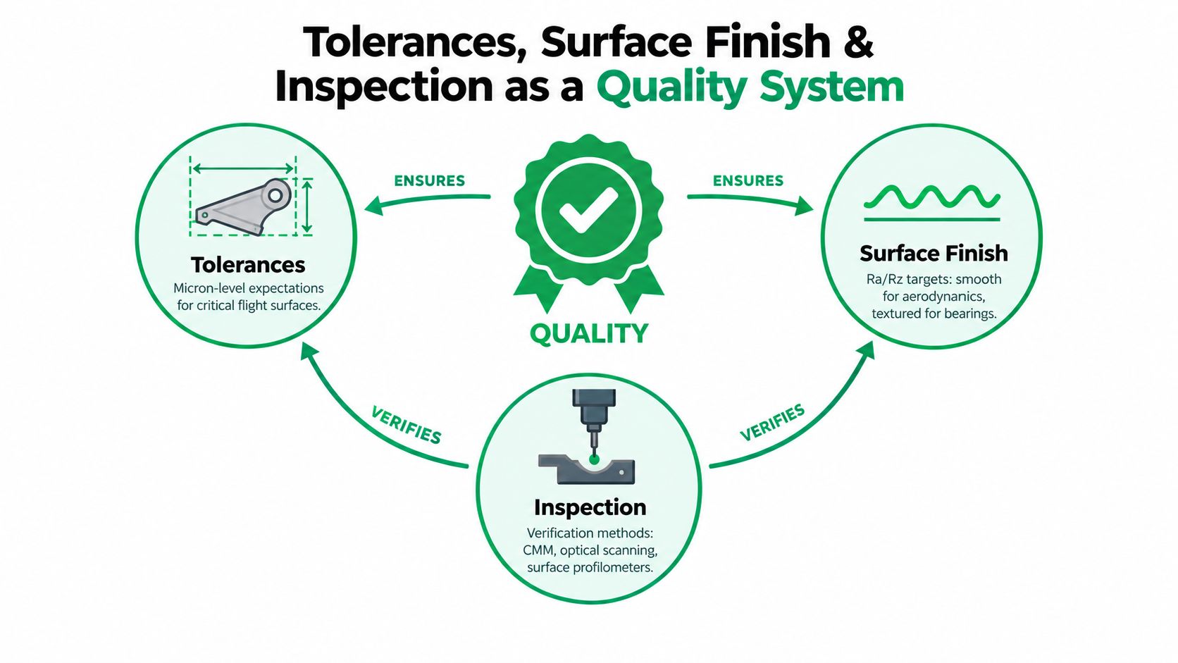
Tolerance defines how far a feature may vary from its nominal size. Surface finish describes the texture left by machining. Inspection supplies evidence that the part meets both requirements. These controls work as one system, much like a flight checklist: each item supports the final decision, and missing context weakens the result.
Start with function, then assign control
Aerospace precision machining commonly uses micron-range dimensional tolerances. Critical features may be held around ±0.0001 inch, approximately ±2.5 µm, while surface roughness may be roughly 16 to 32 µin Ra for aerodynamic surfaces and 4 to 8 µin Ra for bearing surfaces, according to this aerospace machining tolerance guide.
These values are design requirements, not universal defaults. The drawing should connect each tolerance and finish callout to the feature's function. Tighter geometry can reduce drag, support sealing, and improve repeatable fit. It also increases machining time, inspection effort, and process-control demands, so applying the tightest limit everywhere can add cost without improving performance.
The gap between general CNC work and aerospace parts makes that judgment important. Standard CNC capability may be around ±0.010 inch, while aerospace features can require the ±0.001 to ±0.005 inch range, as discussed in this precision machining market overview. A supplier should identify which features need tighter control and which can use wider limits.
Inspection is part of the manufacturing process
A useful inspection plan specifies:
- Datums and alignment, so measurement reflects how the part functions and assembles.
- Critical dimensions and geometric tolerances, including position, flatness, profile, concentricity, or runout where applicable.
- Surface condition, checked with suitable equipment rather than appearance alone.
- Material and process records, connected to the part or lot.
- First article evidence, demonstrating that the drawing was interpreted correctly before the next build.
A CMM verifies complex dimensional relationships. Optical scanning captures broader geometry, while profilometry evaluates surface texture. This CMM inspection service guide explains why measurement planning should follow functional datums instead of a generic checklist.
For prototypes and low-volume runs, the buyer's real bottleneck is often repeatable evidence. The shop must preserve setup logic, inspection depth, traceable records, and process controls so the next part can be judged against the same standard.
The harder question isn't whether a shop can hit a number once. It's whether the shop can explain, measure, and reproduce that result across the next build.
From DFM to Production Readiness for Aerospace Parts
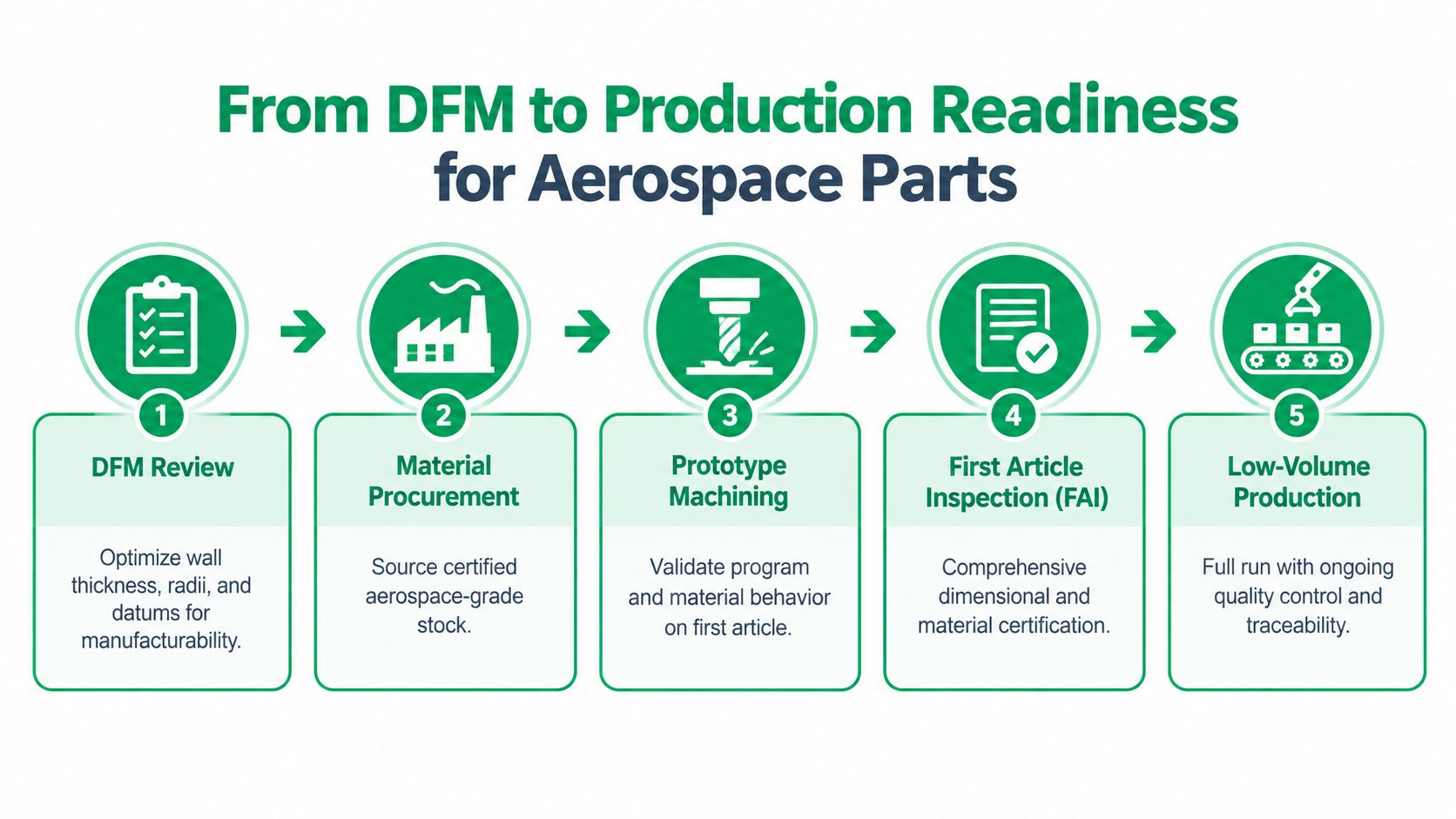
A prototype should answer engineering questions without creating new manufacturing uncertainty. That requires a connected path from design for manufacturing, material procurement, machining, first article inspection, and low-volume production. The buyer's real bottleneck is often the evidence between these steps: repeatable documentation, sufficient inspection depth, and process controls that make the next part comparable to the first.
Step one is a serious DFM review
A useful review examines:
- Wall thickness and unsupported areas, which affect deflection, vibration, and distortion.
- Internal radii, because cutters need practical access, and sharp internal corners may require another process.
- Undercuts and deep features, which can require special tooling, multiple setups, or EDM.
- Datum strategy, so fixturing and inspection use references that match the part's functional interfaces.
- Tolerance stack-ups, so assembly requirements are not assigned to every feature without a clear reason.
The strongest DFM feedback arrives before material is ordered. The supplier should identify dimensions that drive process risk, surfaces requiring special inspection, and geometry changes that protect function while reducing unnecessary machining difficulty.
Build the quality path into the schedule
Material procurement should specify the required certification and identification method. Prototype machining should test the program, fixtures, tool behavior, and material response. First article inspection should verify the drawing as a whole, including features that are difficult or time-consuming to measure.
A low-volume run is ready when the team can state:
- Which features are critical and why.
- Which datums control setup and inspection.
- Which operations carry the greatest variation risk.
- Which outside processes may alter dimensions or surface finish.
- Which records must accompany each part or lot.
- How the team will review and disposition a deviation.
This checklist functions like a flight plan. It connects design intent to physical evidence, so a disagreement can be traced to a feature, operation, measurement, or record instead of becoming a general production argument.
Reduce handoffs without hiding them
Combining machining and finishing can shorten communication paths, but each stage still needs documentation. The buyer should receive material records, inspection results, process certificates, and revision-controlled information.
ISO 9001 provides a general quality-management framework. Aerospace programs may also require customer-specific or industry-specific controls. The practical test is whether operators follow a defined process and whether the records show what happened to each part or lot.
Market demand makes this workflow relevant, yet growth does not solve the buyer's operational problem. A supplier still has to move a specific part from drawing review to verified, repeatable production. For prototypes and low-volume runs, that controlled path often matters more than a machine list or a single successful measurement.
How to Evaluate an Aerospace Precision Machining Supplier
A supplier quote is not a capability statement. It's a promise about a particular part, material, tolerance scheme, inspection package, and delivery path. Evaluate the evidence behind that promise.
Start with the technical questions
Ask the supplier to show how it will handle:
- Critical tolerances, including the proposed process, setup strategy, and measurement method.
- Complex geometry, especially thin walls, deep pockets, compound surfaces, and difficult access.
- Material behavior, including tooling assumptions, heat management, and expected process risks.
- Inspection depth, such as CMM coverage, surface-finish measurement, first article reporting, and record retention.
- Finishing coordination, including who performs the work and how the part remains identified through each handoff.
- DFM feedback, with comments tied to specific drawing features rather than generic approval language.
A supplier that answers only with machine size or axis count is leaving out the controls that determine repeatability. The buyer should ask for a sample inspection report, a clear list of required certifications, and an explanation of how nonconforming parts are handled.
Read the quote as a process plan
Compare quotes by asking what each one includes. A low price may exclude inspection depth, material certification, finishing, tooling development, or a meaningful first article package. A short lead time may depend on unspoken assumptions about material availability, drawing stability, or acceptable substitutions.
FIRMFG is one example of a supplier positioned for this type of work. Its stated capabilities include 300+ in-house machines, 3- to 5-axis CNC milling and turning, wire EDM, ISO 9001 and ISO 13485 quality frameworks, no minimum order quantity, and one-to-one DFM support. Those capabilities should still be matched against the specific aerospace program's requirements, approvals, and documentation expectations.
The decision should end with a controlled next step, not a vague promise. Send the latest drawing, 3D model, material requirement, finish specification, inspection expectations, and target build quantity. Request a DFM review that identifies the critical features, proposed process stack, inspection method, documentation package, and assumptions behind the quoted schedule.
FIRMFG supports aerospace prototype and low-volume programs with CNC machining, 3- to 5-axis milling and turning, wire EDM, material and process coordination, finishing, inspection, and DFM feedback. Share your drawing and requirements with FIRMFG to review a repeatable path from prototype machining through first article and low-volume production.