Plastic Injection Molding: How It Works, Costs and Tooling
You've got a 3D printed prototype that fits, clicks together properly, and survives your bench tests. Then the first injection molding quote arrives, and the tool costs more than everything else in the build combined. Worse, two suppliers quote wildly different part prices for the same CAD file, and neither explains why.
That gap usually isn't margin. It's cooling, cycle time, and tool life, and the cheapest tool can easily become the most expensive way to make ten thousand parts. I would judge every quote on cost per part across lifetime shots, not tool price alone, and the decisions below show you how.
Table of Contents
- How Plastic Injection Molding Works, Step by Step
The Five Stages of One Cycle
What a Good Shot Looks Like
Choose the Right Resin for Your Part- Common Molding Resins and Where They Fit
Design Rules That Prevent Warping and Sink- Design Rule Values for Molded Parts
Rapid Tooling Versus Production Tooling- Tool Types Compared by Life and Lead Time
What Drives Part Cost and Cycle Time- Cost Drivers and the Lever That Moves Each One
Surface Finish, Tolerances and Secondary Operations- Finish Grades in Order
Choose Prototype or Production Molding for Your Next Run- Checklist Before You Commit
How Plastic Injection Molding Works, Step by Step
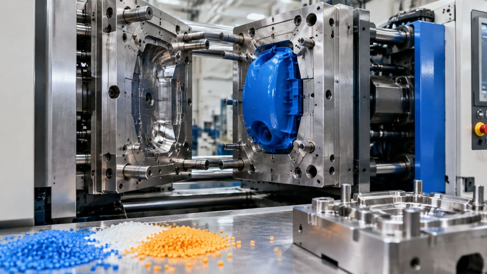
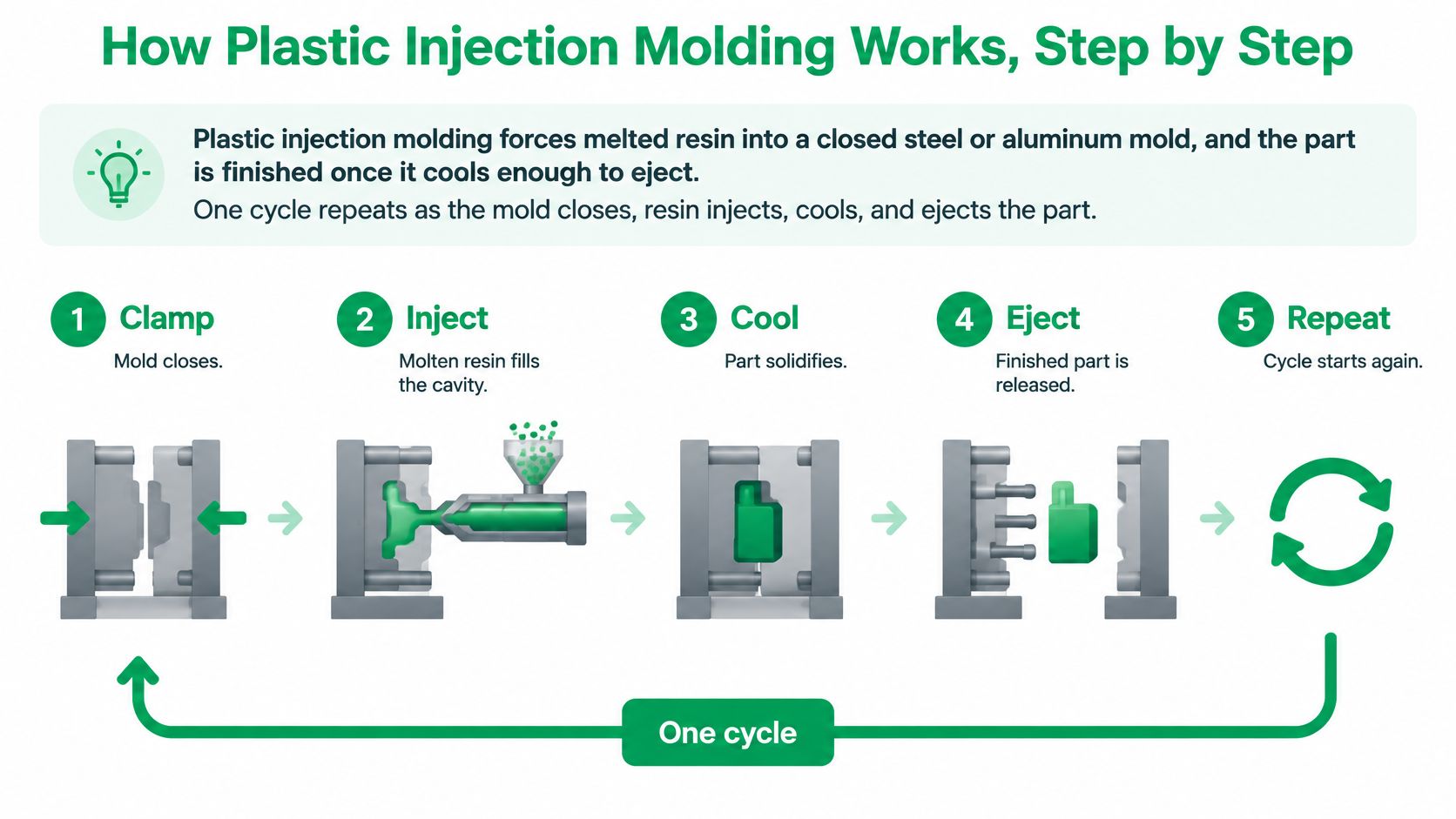
Plastic injection molding forces melted resin into a closed steel or aluminum mold, and the part is finished once it cools enough to eject. One cycle runs from a few seconds for small parts to over a minute for large ones, and each stage has a specific failure that shows up when you rush it.
The Five Stages of One Cycle
- Clamp the mold shut. The press closes both halves and holds them against injection pressure, starting from a common estimate of 2 to 5 tons per square inch of projected part area. Too little force lets melt escape at the parting line as flash, a thin fin you then pay someone to trim.
- Inject. A rotating screw rams melt through the gate into the cavity, and small parts typically fill in one to three seconds. A part that stops short of full fill, called a short shot, usually means the gate or flow path is too restrictive, or air has nowhere to vent.
- Pack. The screw holds pressure so extra melt feeds the cavity while the material shrinks. Packing past gate freeze just adds time, because once the gate solidifies, no more material can compensate for contraction.
- Cool. This is the longest stage and the one that sets your economics. The thickest section governs it, so one solid boss can set the cycle for an otherwise thin part.
- Eject. Pins push the part out. Eject too hot and the part distorts under pin load, warps as it cools unevenly in the bin, or shows white stress marks where the pins landed.
What a Good Shot Looks Like
You want full fill, no flash, no sink marks, and consistent part weight from shot to shot. Weight is the cheap, honest process check, since a drifting weight means filling or packing is drifting before dimensions visibly move. The first shots from a new tool confirm these four things before anyone locks the process settings for production.
Shop rule: If part weight won't repeat, don't chase dimensions yet. Fix the fill and pack first, because the dimensions can't sit still on top of an unstable shot.
The process looks simple, and at scale it's relentless. The 2025 plastics injection molding market analysis placed global volume at approximately 157.13 million metric tons in 2025, with projected volume increasing to 201.47 million metric tons by 2031. Asia-Pacific accounted for 34.10% of that market in 2025, which is why your resin, cooling, and tolerance decisions ripple through supply chains concentrated in that region. This isn't a prototyping technique with a press attached. It's a high-volume process whose economics depend on repeatability and how hard you work the tool.
Choose the Right Resin for Your Part
Read the table by the limitation column first. Strengths sell resin. Limitations redesign your part later, so match the weakness to something your application can tolerate.
Common Molding Resins and Where They Fit
| Resin | Key Strength | Main Limitation | Typical Uses |
|---|---|---|---|
| ABS | Tough, good surface finish, easy to paint and bond | Low UV and heat resistance | Housings, bezels, consumer electronics |
| Polypropylene (PP) | Fatigue resistance, chemical resistance | Warpage, poor paint adhesion | Living hinges, containers, automotive fluid reservoirs |
| Polycarbonate (PC) | High impact strength, optical clarity | Scratches easily, stress cracking with some chemicals | Lenses, guards, medical housings |
| Nylon (PA6/PA66) | Stiffness, wear resistance | Absorbs moisture, dimensions shift | Gears, brackets, structural clips |
| Acetal (POM) | Low friction, dimensional stability | Hard to bond, limited color range | Gears, clips, snap-fits |
| HDPE | Chemical resistance, low cost | Low stiffness, high shrinkage | Containers, caps, drums |
| PMMA (acrylic) | Optical clarity, scratch resistance | Brittle under impact | Light guides, display covers |
| TPU | Flexibility, abrasion resistance | Longer cycle times | Seals, gaskets, grips |
ABS is the default for housings because it is tough, finishes well, and forgives minor design sins, but it will not survive long in direct sun or next to a hot motor. Polypropylene owns the living hinge, flexing through repeated bending zones that crack most resins, yet it warps readily and paint does not stick without surface treatment.
Polycarbonate gives impact strength with clarity, so guards and lenses land here, but it scratches and can stress crack against cleaners that seem harmless on a bench. Nylon PA6 and PA66 bring stiffness and wear resistance for gears and brackets, then absorb moisture and shift dimensions, so you design around the conditioned size, not the dry size off the press.
Resin choice also sets shrinkage and cooling behavior, and cooling sets cycle time. A grade that saves a little on the resin quote but adds time to every shot can cost more across a long run than a higher-priced grade that runs faster. Judge the resin and the tool together by cost per molded part across the life of the tool, not by resin price or tool price alone.
Shrinkage feeds straight into what tolerances you can hold. The mold gets cut oversize by the expected shrinkage, so switching resin families after tooling exists often means parts that measure wrong even when the press runs perfectly. Recycled content or regrind needs the same scrutiny as the base resin. It can change viscosity, shrinkage, moisture sensitivity, color, odor, contamination risk, weld-line strength, and lot-to-lot consistency. On a tight-tolerance or safety-critical part, those shifts matter more than the recycled label itself. I would treat any resin change, virgin to recycled or one recycled grade to another, as a qualification run, with dimensional and mechanical checks on molded parts before you approve it.
Send your molder four things with the CAD: the operating temperature, the load the part carries, chemical exposure, and any regulatory requirement, including food contact or automotive and medical rules. The resin grade then gets confirmed in the quote, with traceability through molding and finishing agreed up front rather than argued about at first article.
Design Rules That Prevent Warping and Sink
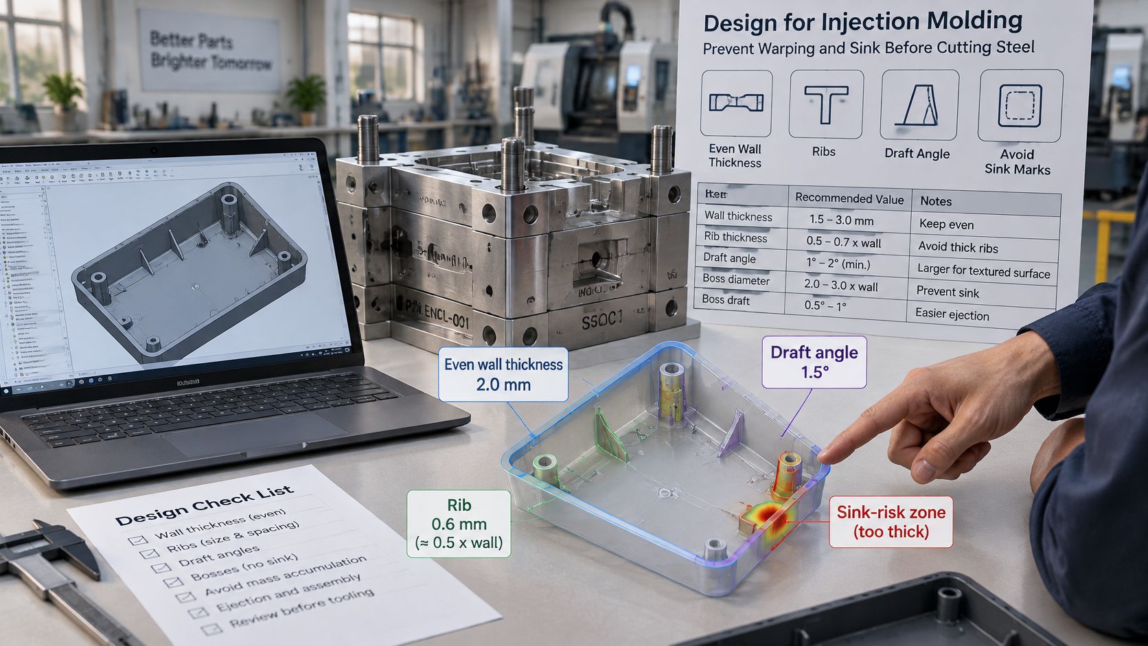
Most molding defects are settled in the CAD model, long before a press runs. A molder can move a gate, raise pack pressure, or stretch the cooling timer, but no process window rescues geometry that freezes at different rates across the part. Run the model against these values before anyone cuts steel.
Design Rule Values for Molded Parts
| Design Element | Rule |
|---|---|
| Nominal wall | 2 to 3 mm for many engineering resins |
| Adjacent wall change | Under about 25 percent |
| Rib thickness | 50 to 60 percent of the nominal wall |
| Draft on smooth faces | At least 1 degree |
| Draft on textured faces | 2 to 3 degrees |
| Corner radius | At least half the wall thickness |
| Boss | Cored out and tied to wall with ribs |
Uniform wall thickness carries most of the result. Melt fills evenly, pressure reaches the end of flow, and every region finishes cooling at roughly the same moment. Put a thick section beside a thin one and the thin side sets while the thick side is still shrinking. That late contraction pulls a sink into the show face or bows the part out of flat.
Ribs add stiffness without adding mass, but only at the ratio above. A rib drawn at full wall thickness drags a visible dimple into the opposite surface, and the fix is thinning the rib, not raising pack pressure. Draft lets the part slide off the core instead of scuffing down a straight wall. Radii spread stress away from sharp internal corners. Cored bosses tied in with ribs give a screw something to bite without leaving a solid lump of plastic that cools on its own schedule.
Cooling Is a Design Feature, Not a Utility
Cooling channel layout decides whether opposite faces of the part solidify at comparable rates. A NIST publication on injection molding process control links mold temperature control, cooling duration, and cooling-channel design to dimensional accuracy, surface quality, mechanical performance, shrinkage, and warpage. Uneven cooling leaves a temperature gradient across the part, and unequal contraction bends or twists it after ejection.
Find the thickest section first, then confirm channels run balanced around the geometry that has to stay flat. If longer cooling stops improving flatness, the limit is thermal imbalance or wall geometry, and reworking channel placement or rib transitions does more than stretching the cycle. Cycle time is the largest controllable share of cost per part, so a design that cools evenly and releases early is worth more across a tool's life than a cheaper mold that has to dwell. A proper DFM review for injection molding catches this on screen, alongside a mold-flow study and a gate location checked against the actual flow path.
The three redesign triggers that cause the most trouble are uneven walls, sharp internal corners, and thick sections placed next to critical features. All three are inexpensive to fix in CAD and costly to fix in steel.
Rapid Tooling Versus Production Tooling
This choice is speed against tool life, not good tools against bad ones. Start with the comparison, then think about how you move from one row to the next without starting over.
Tool Types Compared by Life and Lead Time
| Tooling Type | Typical Material | Tool Life (shots) | Lead Time | Best For |
|---|---|---|---|---|
| Aluminum prototype tool | Aluminum | 1,000 to 10,000 | 1 to 3 weeks | Design validation and bridge builds |
| Aluminum production-grade tool | Aluminum | 10,000 to 100,000 | 2 to 4 weeks | Low-volume runs and pilot builds |
| Pre-hardened steel tool (P20) | P20 tool steel | Several hundred thousand | 4 to 8 weeks | Standard production runs in commodity resins |
| Hardened steel tool (H13 or S7) | Hardened tool steel | Over one million | 6 to 10 weeks | High volume and glass-filled or abrasive resins |
Treat the life figures as ceilings, not promises. An aluminum tool running a soft commodity resin with gentle geometry lives at the top of its range, while the same tool running glass-filled nylon at high clamp force wears edges, grows flash, and can deform long before it. The production-grade aluminum tool sits between the two worlds, with better machining, cooling, and ejection than a quick prototype tool, and it suits pilot builds once the design stops moving.
P20 pre-hardened steel is the standard production answer for commodity and most engineering resins. Step up to H13 or S7 hardened steel when glass-filled or abrasive resins will eat softer surfaces, or when lifetime volume heads past a million shots. Paying for hardened steel to run a few thousand parts in polypropylene is money you'll never recover, and the reverse mistake, running filled resin in aluminum at volume, destroys the cavity finish you paid to create.
The Upgrade Path That Protects Your First Tool
- Design the first tool like the last one. Give the aluminum prototype tool the production gate location and cooling layout, and the steel tool that follows doesn't need a redesign or a new round of debugging.
- Pilot before you commit. Run parts from the prototype tool, build assemblies, and check fit against mating components while changes are still cheap.
- Use bridge tooling deliberately. Lower-cost bridge tools cover a few dozen parts for market testing or certification, but they won't hold tight cosmetic finishes, and they aren't a production plan.
- State your numbers in the request. Expected annual volume, lifetime volume, resin, and how many revisions you expect before release. A quote built without those four inputs is a guess.
Skip the pilot step and the first assembly problem arrives after you've paid for hardened steel, where every fix means weld, remachine, and requalify. I've no patience for that trade, and you shouldn't either. The volume bands in the closing section turn this table into an actual decision for your run.
What Drives Part Cost and Cycle Time
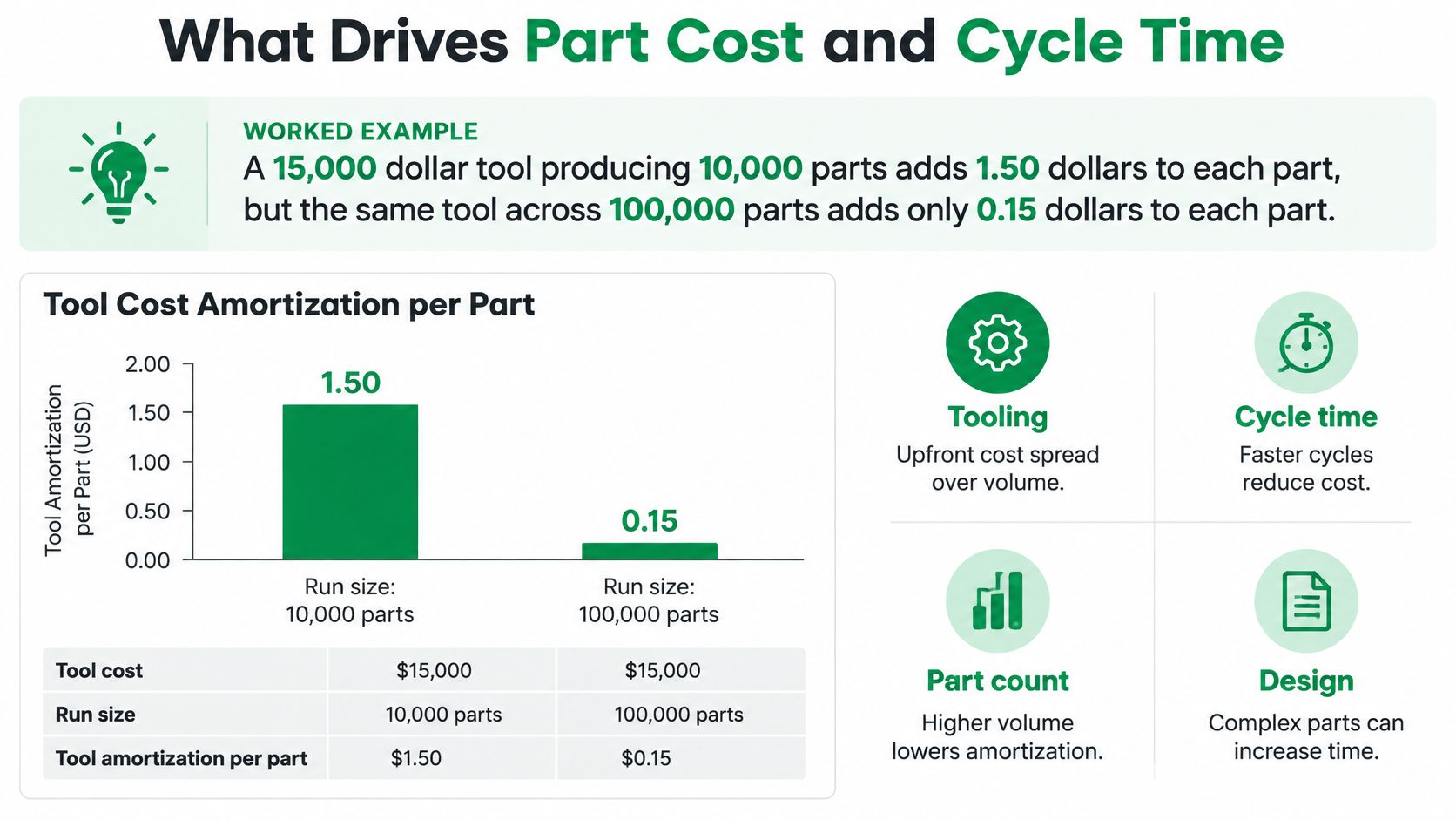
Work the arithmetic once and the whole quote makes sense. A 15,000 dollar tool producing 10,000 parts adds 1.50 dollars to each part, but the same tool across 100,000 parts adds only 0.15 dollars. Tooling is a fixed cost spread over volume, while material, press time, and secondary labor repeat on every single part.
Cost Drivers and the Lever That Moves Each One
| Cost Driver | How It Affects Price | Lever to Pull |
|---|---|---|
| Cycle time | Every second of cooling adds to every part | Thinner uniform walls and balanced cooling channels |
| Cavity count | More cavities cut per-part tooling cost up to a point | Family molds or multi-cavity tools for high volume |
| Tool steel grade | Sets tool cost and tool life | Aluminum for prototype volumes, steel for production |
| Part weight and resin grade | Material cost scales with shot weight | Lighter wall design and cheaper resin where the spec allows |
| Surface finish grade | Highly polished cavities add tooling labor | Specify high-gloss finish only on cosmetic faces |
| Secondary operations | Trimming, painting and assembly add labor per part | Design out undercuts and post-mold steps |
Cycle time is usually the largest variable cost, and cooling is its main component, which is why a cheaper tool with poor channels can cost more per part forever. A 2025 peer-reviewed review of polymer processing reported that cooling accounted for approximately 41% of total energy use in an ABS injection-molding analysis, while plasticizing accounted for 21% and holding for 14%.
That figure measures energy share, not cost share, so use it to rank where energy goes and confirm the cost effect against your molder's machine rate and cycle-time quote. It still overturns a common assumption. Replacing the press isn't automatically the biggest gain, and I would ask first whether to optimize the cooling circuit, the mold design, or the cycle itself before anyone specifies a new machine.
The practical lever is thickness. Reduce the thickest section, rebalance cooling around what remains, then check the part still ejects cleanly without distortion. A thorough breakdown of injection molding cost drivers follows the same logic. For volumes under a few thousand parts, cut tool cost first, since amortization dominates. Above tens of thousands, cycle time and cavity count decide the price, and that's where a better-cooled, more expensive tool earns its keep.
Surface Finish, Tolerances and Secondary Operations
Finish and tolerance are set in the mold and the process, not added at the end. Whatever the cavity surface looks like, the part will copy, so you specify both before tooling, not after the first parts disappoint you.
Finish Grades in Order
- SPI A-1 and A-2. High-gloss polish for clear parts and cosmetic faces that customers inspect closely. This takes real bench labor in the tool shop, and every hour of it lands in your tooling price.
- SPI B. Semi-gloss, a sensible middle ground for visible housings that don't need a mirror.
- SPI C and D. Matte and textured surfaces, often specified against VDI texture references for grained finishes. Texture needs the extra draft from the design rules, and it usefully hides light sink and flow marks that a polish would advertise.
Specify high gloss only where eyes go. Polishing a surface that sits inside an assembly buys nothing.
Standard molded tolerances run typically around plus or minus 0.1 mm across the first 25 mm of a dimension. Tighter values are possible on critical features, but they demand better steel, tighter process control, and more inspection, and tolerance stack-up across a multi-part assembly eats margin fast. Put tight numbers only on dimensions that control fit or function.
Secondary Operations Worth Planning For
Insert molding places metal threads or pins in the tool so plastic forms around them, giving you a durable thread no self-tapping screw in plastic will match. Design for insert pull-out, with knurls or undercuts on the insert and enough plastic around it. Two-shot and overmolding add soft-touch grips or seals in a second material, and the bond line between materials is the design point, since incompatible resins peel apart in service. Ultrasonic welding joins housing halves without fasteners, provided you design an energy director into the joint from the start. Pad printing and hot stamping handle logos and labels, where ink adhesion to your specific resin decides whether the graphic survives handling.
Mark cosmetic faces and critical dimensions directly on the drawing. If the molder has to guess where finish and tolerance matter, you'll pay to hold both everywhere.
Choose Prototype or Production Molding for Your Next Run
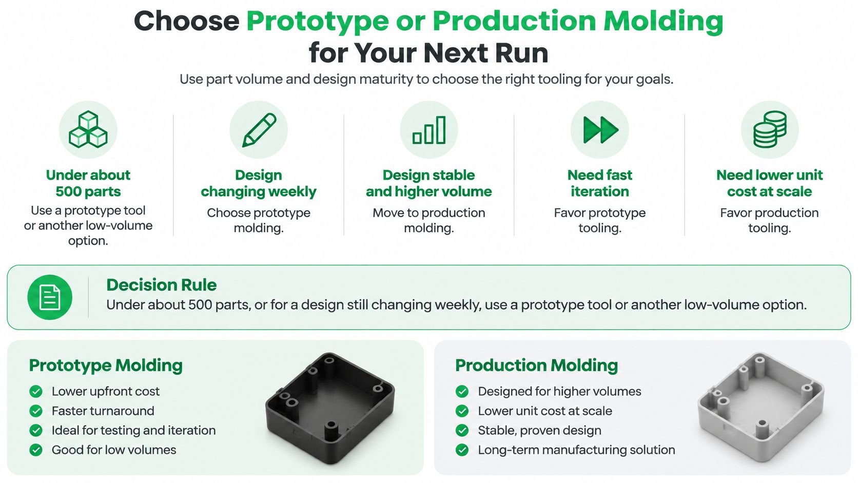
Volume and design maturity make this decision, and the bands are straightforward. Under about 500 parts, or while the design still changes weekly, use a prototype tool or another low-volume route, and accept a higher per-part price in exchange for low up-front cost and fast changes.
From 500 to about 10,000 parts, build an aluminum production-grade tool once the design is frozen, and keep a steel upgrade in the plan if demand grows. Above about 10,000 parts, specify a steel tool and budget for a full DFM review before cutting it, because at that volume the tool should be judged on cost per part over its life, not its invoice.
Checklist Before You Commit
- Geometry checked. Wall thickness, draft, ribs, and radii verified against the design rules, with the thickest section identified.
- Resin picked with a plan. Grade selected for temperature, load, and chemicals, plus a qualification run if regrind or recycled content is involved.
- Volumes stated. Annual and lifetime quantities in writing, so tool class and cavity count rest on numbers, not optimism.
- Critical faces defined. Finish grades and tight tolerances assigned only where they earn their cost.
- Pilot run budgeted. One build to test assembly fit before production tooling is a sunk cost.
FIRMFG offers plastic injection molding from prototype to production, with 100+ materials and no minimum order, so the bands above map onto a single tooling path rather than a supplier change mid-program. Our engineers suggest the optimal resin grade, Shore hardness, and mold strategy to meet functional and cosmetic requirements in the quote. A detailed guide to prototype injection molding routes covers the low-volume end in more depth.
The single next action is simple. Send the CAD file, expected volumes, and critical requirements to FIRMFG for a DFM review and quote, and you'll get back the tooling route your numbers support.
If your CAD is ready but the tooling quotes don't agree, send us the file with your annual and lifetime volumes and we'll return a DFM review covering resin grade, cooling strategy, and the tool class that gives you the lowest cost per part across the run. FIRMFG handles plastic injection molding from prototype tools to production steel, so you can validate fit on a pilot build and scale without requalifying a new supplier. Start your review today with FIRMFG and get a quote built on cycle time and lifetime shots, not just tool price.