CNC Machining Metal Parts: A Practical Engineer's Guide
You've got a metal part ready for quotation, but the design has a deep pocket, a thin wall, and tight callouts on nearly every face. The CAD model looks finished. The cost and lead time aren't clear, and changing the drawing after the first quote could mean starting the review again.
The practical way to control that risk is to make each feature earn its complexity. Choose the process around the geometry, specify material and tolerances with the part's function in mind, and decide how each important dimension will be inspected before production starts.
Table of Contents
Metals Worth Machining and What Each Costs You
Tolerances That Protect Function Without Adding Cost- Spend the tolerance budget on function
Design Features That Drive Price and Lead Time- Match tool choice to the feature
From Prototype to Low-Volume Run and Lead Times- Ask for the schedule by stage
Inspection Methods That Prove Your Tolerances- Build the report around the drawing
Choose a Supplier by Evidence and Verify the Claims
Which CNC Process Fits Your Metal Part
Choosing a CNC process is like picking a tool from a workshop rack. The feature set decides, not the brand of machine. A flat bracket and a turned shaft may share the same alloy, but they don't call for the same operation or setup.
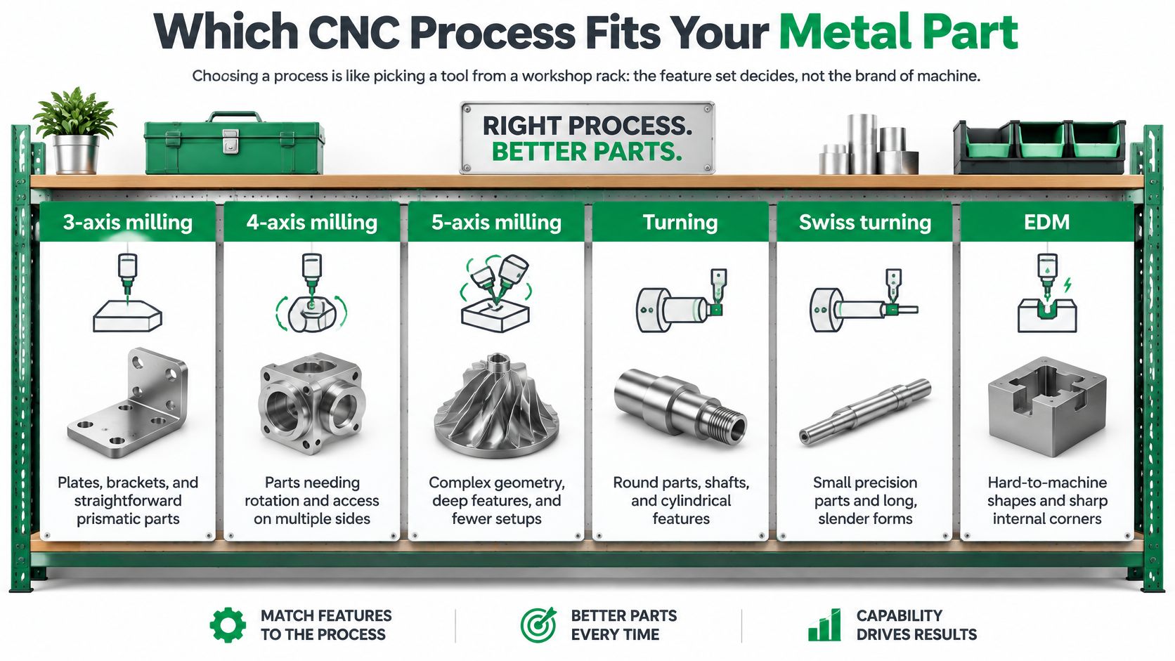
| CNC processes compared for metal parts | Best for | Typical features | Main limit |
|---|---|---|---|
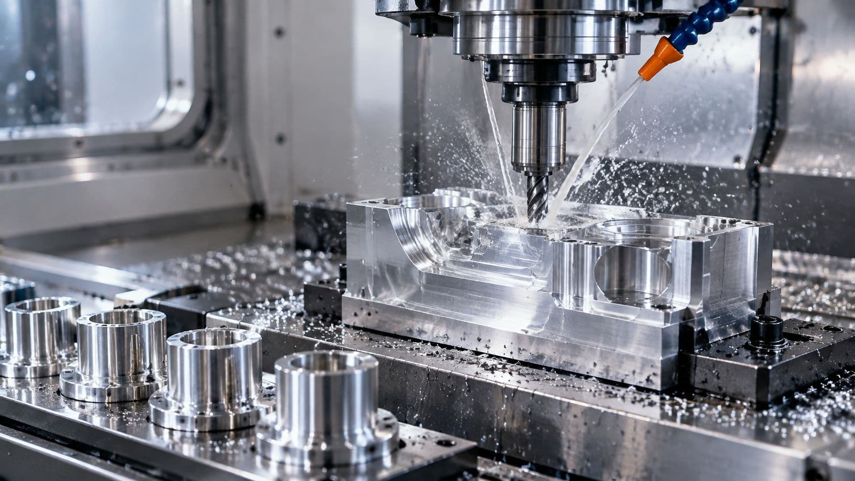
| 3-axis milling | Plates, brackets, prismatic housings | Pockets, slots, flat faces machined from one side | Undercuts and compound angles need re-setup |
| 4-axis milling | Parts with features around one axis | Indexed holes, cam profiles, helical grooves | Still can't reach undercuts on other faces |
| 5-axis milling | Complex contours and multi-face parts | Impellers, housings, sculpted surfaces, undercuts | Higher machine rate and more programming effort |
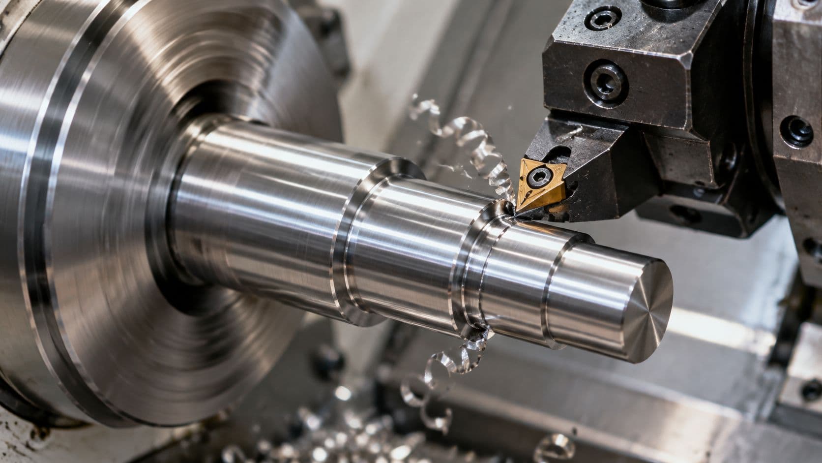
| CNC turning | Shafts, bushings, round parts | Diameters, threads, grooves, bores | Non-round features need milling or turn-mill |
| Micro machining | Miniature metal features | Sub-millimetre holes, fine pockets, tight detail | Higher tool-breakage risk and smaller feed rates |
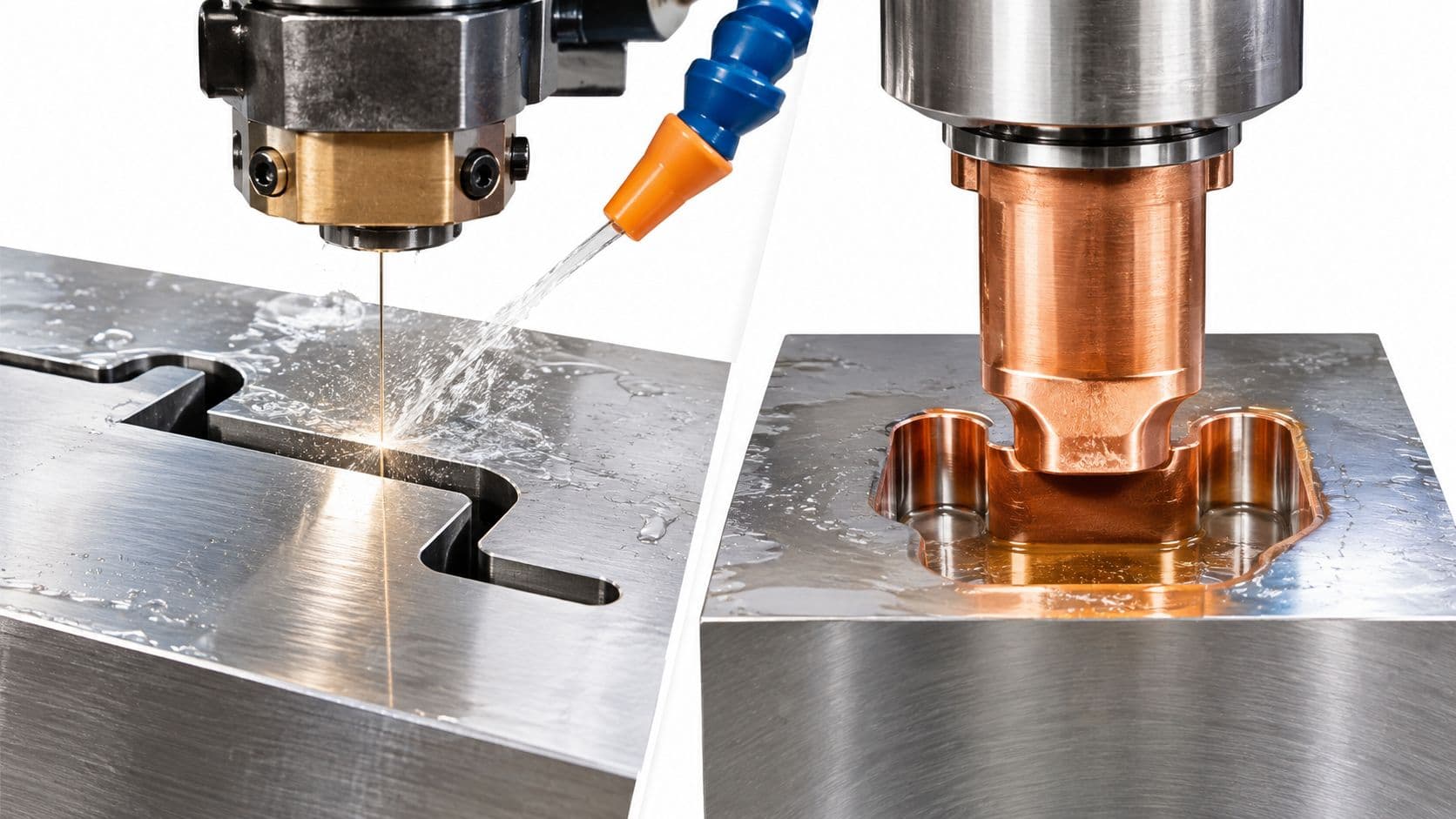
| Wire EDM | Hardened steel and sharp internal corners | Thin slots, precise profiles, internal corners | Conductive materials only; slower on thick stock |
Start with the geometry
Three-axis milling is a straightforward choice for a plate or housing whose important features can be reached from one direction. If the part needs holes or grooves distributed around a cylinder, four-axis milling can rotate it between cuts and reduce the need to remove and reposition it manually. That indexing capability doesn't mean every side or undercut is accessible, so check tool approach before assuming one setup will cover everything.
Five-axis milling moves the tool or part through more orientations, making it useful for compound surfaces and features that would otherwise need several setups. That access comes with a trade-off: programming and machine time can cost more. Use it when the geometry or setup reduction justifies it, not because the machine is more capable.
For shafts, pins, and bushings, turning is often the natural fit because the stock spins as the cutting tool shapes it. A turn-mill machine can add flats or cross-holes to a round body without sending it to a separate milling setup. For more detail on where turning fits, see this guide to CNC turning and turned-part features.
Apply a three-question test
Ask: What features exist? How many faces need access? Is the part round? Those answers narrow the process quickly. A small feature may call for micro machining; a sharp internal corner in hardened steel may suit wire EDM, which works only on electrically conductive materials.
Practical rule: Favor the process that reaches the critical features with the fewest reliable setups. Every extra re-fixturing step creates another opportunity to introduce alignment error, and it adds handling and setup work.
Metals Worth Machining and What Each Costs You
Material choice affects cutting behavior, surface finish, and tool life before a tolerance callout enters the conversation. Choose a grade for the part's job, then state the exact grade and temper so a supplier can quote the intended material rather than a broad family.
| Common machining metals and what to expect | Machinability | Typical use | Watch for |
|---|---|---|---|
| Aluminum 6061-T6 | Good | General brackets and housings | Specify temper; manage burrs and built-up edge |
| Aluminum 7075-T6 | Fair | Structural, high-strength parts | Harder cutting; tool wear rises sooner |
| Stainless steel 304 | Fair | Corrosion-resistant housings and fittings | Work-hardening and slower cutting |
| Stainless steel 316 | Fair | Parts exposed to corrosive environments | Work-hardening and slower cutting |
| Carbon steel 1018 | Good | Shafts, fixtures, and general hardware | Protect against corrosion if the service environment requires it |
| Alloy steel 4140 | Fair | Shafts and load-bearing components | Heat treatment adds a process and inspection step |
| Titanium Ti-6Al-4V | Poor | Aerospace parts and medical implants | Low heat conductivity; slow speeds and high cost |
| Brass C360 | Excellent | Fittings and small precision parts | Confirm that its strength and service properties suit the application |
| Copper | Poor | Electrical and thermal parts | Stringy chips; soft and hard to hold |
Aluminum often looks easy to machine, but the tool edge can change how the part comes off the machine. Built-up edge, where aluminum adheres to the tool, can contribute to burrs, smearing, poor finish, and dimensional drift. Sharp, positive-rake edges, polished or PCD tooling, and cutting fluid help control the problem. For aluminum milling, Sandvik Coromant's guidance on machining different materials gives a recommended cutting-speed range of 150–250 m/min.
The same guidance sets a flank-wear maximum of approximately 0.2 mm for a cutter with a 90-degree entering angle, or 0.3 mm for round inserts. As the edge wears or material sticks to it, the tool's effective geometry changes. Cutting forces and rubbing increase, which can degrade the finish and push dimensions outside tolerance.
Coolant concentration should reflect the alloy's silicon content: roughly 5% below 8% silicon, 10% for 8–12%, and 15% above 12% silicon, according to the same aluminum milling recommendations. For repeated parts, agree on an inspection limit for tool wear before defects appear.
When you specify aluminum, put the grade, temper, and required finish on the drawing. “Aluminum” alone leaves too much room for a mismatch in strength, machinability, or surface expectations. Compare options in this guide to CNC machining materials.
Tolerances That Protect Function Without Adding Cost
A tight tolerance can change how a part is machined and inspected. Apply it where it controls fit, movement, sealing, or assembly; use general tolerances elsewhere.
ISO 2768-1 applies to dimensions without individual tolerance callouts when the drawing specifies the standard and a tolerance class. Its linear tolerances are:
| ISO 2768-1 linear dimensions | Fine (f) | Medium (m) | Coarse (c) | Very coarse (v) |
|---|---|---|---|---|
| 0.5 to 3 mm | ±0.05 mm | ±0.10 mm | ±0.20 mm | Not specified |
| Over 3 to 6 mm | ±0.05 mm | ±0.10 mm | ±0.30 mm | ±0.50 mm |
| Over 6 to 30 mm | ±0.10 mm | ±0.20 mm | ±0.50 mm | ±1.00 mm |
| Over 30 to 120 mm | ±0.15 mm | ±0.30 mm | ±0.80 mm | ±1.50 mm |
| Over 120 to 400 mm | ±0.20 mm | ±0.50 mm | ±1.20 mm | ±2.50 mm |
For example, a 20 mm dimension assigned the medium class allows ±0.20 mm. Specifying ±0.01 mm instead can require more controlled machining and dedicated inspection, or a design change.
Spend the tolerance budget on function
Before releasing the drawing:
- List dimensional, geometric, and surface-finish callouts.
- Mark which ones control function. Bearing bores, mating fits, and assembly datums are common examples; cosmetic faces and non-mating clearances may not need tight limits.
- Identify how each functional requirement will be machined and inspected.
- Tighten only the callouts that protect performance. Avoid applying a tight tolerance to every dimension by default.
- Test whether a design change, such as a larger internal radius or a relaxed flatness requirement, can remove a costly toolpath or inspection step.
Features interact. A thin wall beside a deep pocket, a small internal radius, a difficult material, and a tight positional tolerance can together add setups, tooling, inspection, and scrap risk. One published DFM analysis of CNC-machined metal parts estimates that early design decisions can increase manufacturing lead time by 25% to 1,480% and cost by 15% to 800%, depending on feature complexity and combinations. Those ranges illustrate how design choices can compound; they are not estimates for an individual part. Review the tolerance budget while the design can still change.
Design Features That Drive Price and Lead Time
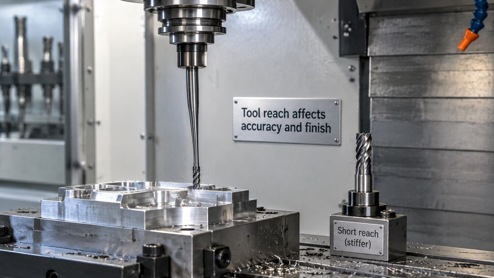
A milling cutter behaves roughly like a cantilevered beam: the longer its unsupported reach, the more it can bend under cutting force. That deflection can show up as chatter, dimensional error, poor finish, or premature edge damage. The University of Florida's CNC guidance notes that stiffness falls sharply as unsupported length grows, so the first fix is often the shortest tool that reaches the feature, not a more expensive machine.
Match tool choice to the feature
Fewer flutes leave more room for chips to escape, which helps in deep slots. More flutes can add stiffness and productivity, but for full-slot milling of nonferrous materials such as aluminum, the University of Florida recommends no more than three flutes. The right choice depends on whether chip evacuation or tool stiffness is the limiting issue.
Don't suppress vibration by reducing feed until the cutter rubs instead of cutting. The same guidance says to avoid feeding below 25% of the recommended feed per tooth. For a 12.7 mm end mill specified at 0.004 in/tooth, feeding below approximately 0.001 in/tooth can promote rubbing.
Fix the geometry that forces difficult cutting
- Deep, narrow pockets: Long, small-diameter cutters deflect and may chatter. Make the pocket shallower, widen it where function allows, or provide a larger access opening.
- Thin walls: Cutting force can push a slender wall away from the tool, leaving it distorted or out of tolerance. Add thickness, support the wall in the design, or machine it in a sequence that leaves more material in place until late in the operation.
- Small internal corner radii: A cutter can't make an internal corner sharper than its own radius. Increase the radius where the mating part permits, or add a relief at the corner.
- Deep holes: Holes much deeper than their diameter make chip removal and tool control harder. Shorten the hole, enlarge it, or use a suitable drilling strategy and specify only the depth the assembly needs.
- Undercuts: These can require specialized tools, extra orientations, or another setup. Redesign the feature for straight tool access when the undercut doesn't perform a necessary function.
- Opposite-face features: Re-fixturing to machine the other side adds handling and alignment work. Move features to a common access direction where the part's function allows.
During DFM, specify tool reach, diameter, flute count, and minimum chip load together. Reviewing those items as a set is more useful than asking whether a feature is technically machinable. The practical question is whether it can be cut and measured consistently without forcing an avoidable tool or setup compromise.
From Prototype to Low-Volume Run and Lead Times
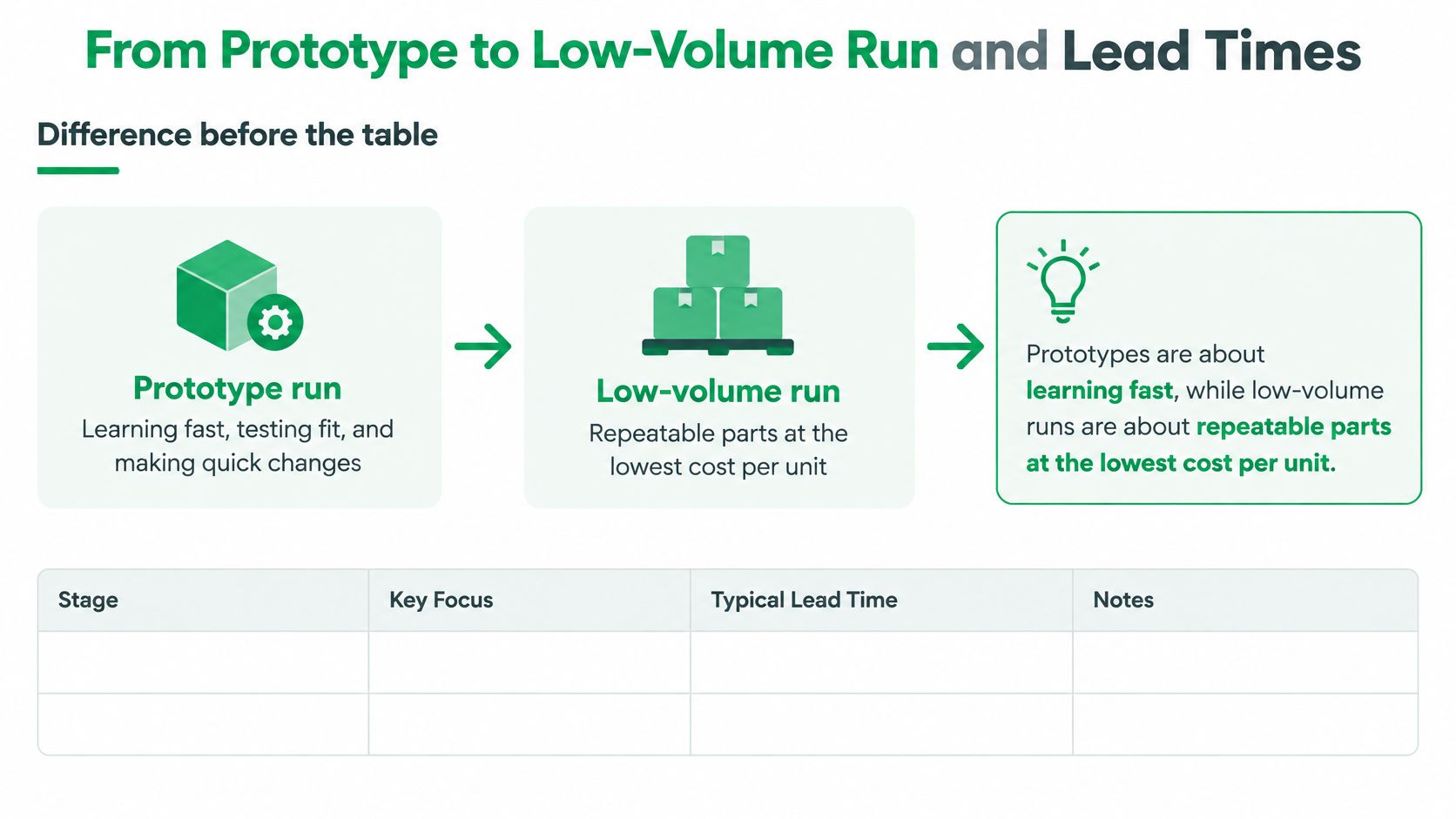
Prototypes are about learning fast, while low-volume runs are about repeatable parts at the lowest cost per unit. A prototype may justify a one-off setup to answer a design question. A repeated run needs stable fixturing, agreed inspection, and a process that can reproduce the part without rebuilding the plan each time.
A useful workflow is: 1. Submit the STEP file and drawing with tolerance callouts, material, finish, and quantity. 2. Review DFM notes covering features, tolerances, and setups. 3. Approve the revised drawing. 4. Allow programming, fixturing, and a first-article run. 5. Review the inspection report and agree on any design changes. 6. Run the batch with the agreed sampling inspection and delivery plan.
| Run type | Primary goal | What to settle before the run |
|---|---|---|
| Prototype | Learn quickly and test the design | Fit, function, material, and needed drawing changes |
| Low-volume run | Repeat parts at a controlled unit cost | Stable setup, inspection plan, material, and finish |
Ask for the schedule by stage
Material stock can affect the start date, especially when the specified grade or form isn't on hand. Outsourced finishes such as anodizing and plating add a handoff and their own time in the schedule. Heat treatment for 4140 also takes the part beyond the cutting operation, so confirm where that stage sits and whether inspection follows it.
For a larger run, fixture design and build may become part of the schedule. Inspection depth matters too: checking every dimension on every part takes a different amount of time than inspecting the first article and using an agreed sampling plan for the batch.
Measure lead time from approved drawing to shipment, not from the date you requested a quote. Ask for a breakdown that separates machining from finishing, inspection, and shipping, so a short machining estimate doesn't obscure a longer overall schedule.
A 3D-printed form check can run in parallel with drawing review when the immediate question is fit or access rather than metal performance. That can help expose an interface problem before committing to machined parts. It doesn't replace a metal prototype when the design needs validation of the actual material, finish, or machining result.
Inspection Methods That Prove Your Tolerances
Name the measuring method for each functional callout before the first part is cut. Calipers can quickly check a length or outside diameter, but they don't report a hole's position relative to a datum. A coordinate measuring machine (CMM) can verify three-dimensional positions, flatness, and profile against the drawing or CAD model.
| Inspection methods and what they verify | Verifies | Best for | Limit |
|---|---|---|---|
| Calipers and micrometers | Linear and diameter dimensions | Quick in-process checks | Operator-dependent; no position data |
| Height gauge and optical comparator | Feature heights and profiles | Stepped parts and small contours | Limited to two-dimensional views |
| Coordinate measuring machine (CMM) | 3D positions, true position, flatness | Tight tolerances and first-article reports | Slower; needs part fixturing |
| Surface roughness tester | Ra surface-finish value | Sealing faces and bearing surfaces | Samples only a small area |
| Thread gauges | Thread fit and form | Threaded features | Only for standard thread forms |
Build the report around the drawing
A first-article inspection report records the drawing dimensions for the first part. It gives the team a chance to catch a machining or interpretation issue before it carries into the batch. For positions and geometric relationships, specify how the datum structure will be measured, not just that the supplier will “inspect the part.” CMM inspection services can be relevant when the drawing calls for coordinate-based verification.
Use the tool that matches the requirement. A thread gauge can check whether a standard thread form fits its gauge, but it won't prove the position of the threaded hole. A roughness tester reports a surface-finish value in a small sampled area; it doesn't establish that every area of a face has the same finish.
Traceability helps explain what produced a measured result. Material certificates tie the grade and heat to a lot, while process records can identify the machine and tool associated with production. Quality systems such as ISO 9001 support documented controls; IATF 16949 adds automotive-specific production requirements, including production part approval.
Match each functional tolerance to a named measuring method, and ask for the inspection plan and a sample report with the quote.
Choose a Supplier by Evidence and Verify the Claims
A low quote doesn't tell you whether the supplier can reach the part's features, verify its functional dimensions, or ship on the required schedule. Score each quote against the same evidence checklist. Turn any missing item into a question to resolve before ordering.
- Process range: Can the supplier perform the milling, turning, micro work, or EDM the geometry calls for?
- Material identification: Will the material certificate identify the exact grade and heat?
- Inspection capability: Can the supplier measure the critical features and provide a first-article report?
- Written DFM feedback: Does the quote identify difficult features, tolerance concerns, and setup requirements?
- Traceable records: Can the supplier connect the material lot and production records to the work?
- Stage-by-stage schedule: Does the lead-time estimate account for machining, finishing, inspection, and shipment?
A capability statement is a starting point, not proof that a specific part will meet its requirements. FIRMFG is a Shenzhen-based CNC manufacturer that states it provides a free machining quote within 24 hours of CAD upload, can deliver parts in as fast as 3 days with rush service available, and offers tolerances as tight as ±0.0005 inch on select work. Treat those as provider claims to verify against the drawing, first article, and schedule for your job.
For your comparison, ask every supplier the same questions. If one quotation omits inspection or finishing, have that stage clarified rather than assuming it's included. If a tight tolerance drives the price, ask which feature, setup, or measurement method is responsible. The answer should help you decide whether to keep the requirement or change the design.
Prepare one complete drawing pack with the model, material and finish requirements, functional tolerances, quantity, and inspection expectations. Send it to two or three suppliers, score each response against the checklist, and approve the first article before authorizing the batch.
FIRMFG offers 3-, 4-, and 5-axis CNC machining, turning, micro machining, and wire EDM for metal parts, with support for prototyping and low-volume production. Send a complete drawing pack to FIRMFG to request a quote and get DFM feedback on the features, tolerances, and inspection needs that shape your part's cost and schedule.