What Is CNC Turning and How Does It Actually Work
You're reviewing a drawing for a shaft, sleeve, hub, or threaded connector, and the part looks simple because most of its features are round. Then the quoting questions start. Should it be turned or milled? Does every diameter need the same tolerance? Will a prototype still be economical once setup, inspection, and finishing are included?
Those questions get to the practical meaning of what CNC turning is. The process itself is straightforward to describe, but choosing it well requires understanding how the workpiece rotates, how tools remove material, how tolerances affect the process window, and where turning stops being the sensible choice.
Table of Contents
- What CNC Turning Actually Means on the Shop Floor
- How CNC Turning Evolved Into What It Is Today
Each milestone added a capability
Step by Step Inside a Turning Operation- 1. Review the quote and choose stock
- 2. Build the tool path
- 3. Set up the machine
- 4. Rough, finish, and control the cut
- 5. Complete secondary features
- 6. Inspect and release
CNC Turning vs Milling vs Turn-Milling
Materials Tolerances and Surface Finish You Can Expect- Match finish requirements to function
Design for Manufacturability Tips That Save Real Money- Hold tolerance where the part needs it
Lead Times Cost and When Turning Makes Sense for Low Volumes- Setup is the economic hinge
Key Takeaways Before You Quote Your Next Turned Part
What CNC Turning Actually Means on the Shop Floor
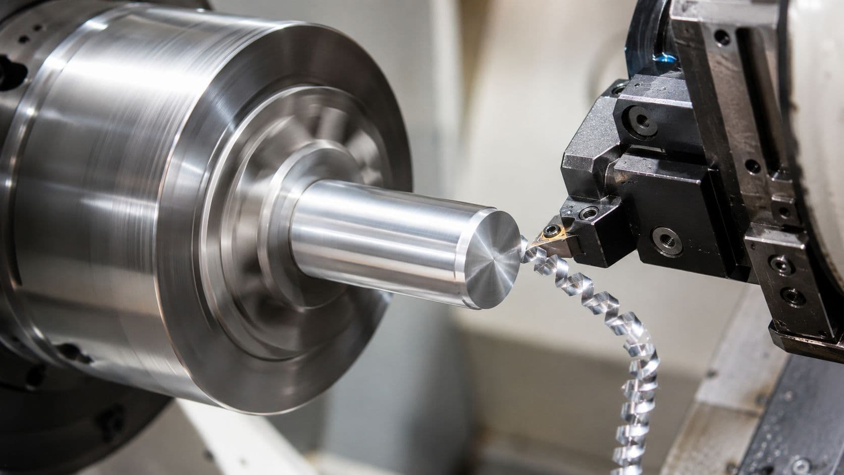
Stand beside a turning center while a bar of 6061 aluminum spins in the chuck. The spindle rotates the workpiece, while a single-point carbide insert moves into its outside diameter and peels away a bright ribbon of swarf. You'll hear the steady spindle tone, the hiss of coolant, and the change in cutting sound when the tool reaches a shoulder or groove.
That scene gives you the working definition. CNC turning is a subtractive machining process in which a rotating workpiece meets a cutting tool whose movement is controlled by a computer program. The program, usually expressed through G-code generated from CAM software, controls tool movement, spindle behavior, cutting passes, and auxiliary operations. The operator still sets the machine, verifies offsets, monitors the cut, and responds to variation, but the machine no longer depends on hand-wheel movement for each feature.
Turning suits parts whose important surfaces share a central axis. Typical examples include:
- Shafts and pins, where outside diameters, shoulders, and grooves must stay concentric.
- Bushings and sleeves, often produced from bar stock with a drilled or bored internal diameter.
- Hubs and spacers, which combine turned diameters with faces and bores.
- Threaded components, including fasteners, adapters, and valve hardware.
- Valve bodies and nozzles, when their primary geometry remains rotational.
A basic 2-axis CNC lathe moves the tool along the workpiece's length and toward its centerline. A live-tool turning center adds powered drills, taps, and milling cutters, while a multi-axis mill-turn machine can combine turning and milling with features such as a second spindle or Y-axis movement. Tooling may include carbide inserts for roughing and finishing, drills, boring bars, taps, knurlers, grooving tools, and parting blades.

The essential distinction is simple: the part supplies the rotational motion, and the tool removes material in a controlled path. That arrangement makes cylindrical geometry efficient, repeatable, and naturally suited to concentric features.
Shop-floor rule: If the part's main features revolve around one centerline, start your process conversation with turning.
How CNC Turning Evolved Into What It Is Today
The modern turning center is the result of several changes that each removed a specific limitation from manual machining. Lathes existed in ancient times, including human-powered arrangements that rotated a workpiece while a cutting tool shaped it. The industrial engine lathe later added mechanical power and more controlled feeds, allowing operators to cut metal with greater consistency.
The decisive transition came with numerical control. John T. Parsons and MIT helped develop numerical control in the 1940s and 1950s, and MIT demonstrated one of the first continuous-path numerically controlled milling machines in September 1952, as described in this history of CNC machining. Although that early machine was a mill, the same NC-to-CNC development changed lathes and turning centers by replacing direct manual control with programmed movement.
G-code emerged from MIT's Servomechanisms Lab in the mid-1950s. That programming language gave machines a repeatable way to define tool paths, feeds, spindle actions, and machining sequences. By the 1960s and 1970s, computer-controlled CNC systems were replacing earlier punched-card and electromechanical methods, making automated turning more practical for production work.

Each milestone added a capability
Later machine development focused on control and setup reduction. Closed-loop servo systems helped the machine correct motion more accurately. Microprocessors replaced less flexible tape-based control, while live tooling and subspindles allowed one machine to drill, tap, mill, and transfer a part without sending it immediately to another station.
Multi-axis machines added Y-axis movement and more capable mill-turn cycles. A designer can now specify a turned body with cross-holes, flats, slots, or off-axis features and have those operations completed in a coordinated workflow.
Today's connected machines may also use thermal compensation, tool-life monitoring, and production data collection. Those features don't change the basic cutting principle. They make the turning center better at managing heat, tool wear, repeatability, and unattended production.
Step by Step Inside a Turning Operation
A turned part starts with a drawing, not with a spindle. The programmer and estimator first identify the material, stock form, critical features, tolerances, finish requirements, quantity, and downstream operations.
1. Review the quote and choose stock
The shop decides whether bar stock, a cutoff, or a billet makes sense. Bar stock often suits long, rotational parts because the machine can feed and cut successive components with limited handling. A billet may be more appropriate when the outside diameter is large relative to the finished geometry or when the part needs a short, custom blank.
Material form matters too. Drawn and extruded stock can behave differently during cutting because of residual stress, hardness variation, and dimensional condition. The choice affects waste, workholding, chip formation, and the amount of material the tools must remove.
2. Build the tool path
CAM programming divides the job into operations such as facing, rough turning, finishing, boring, grooving, threading, drilling, and parting. Roughing removes material efficiently while leaving stock for the finishing tool. Finishing then establishes the final diameter, shoulder location, and surface texture.
The programmer also defines work offsets, tool compensation, safe clearances, and stock allowances. A good tool path doesn't just reach the nominal dimensions. It protects the chuck, avoids collisions, manages chip flow, and leaves enough material for a stable final pass.

3. Set up the machine
The operator installs a chuck, collet, or mandrel based on the part's size, grip length, surface condition, and required concentricity. Collets can provide repeatable support for bar work, while jaws offer flexibility for varied diameters. A mandrel may hold a part from an internal feature when the outside surface must remain accessible.
The operator presets tools, loads the program, establishes the work coordinate system, and checks the datum. If the machine has a subspindle, the transfer position and secondary datum must be verified before the part moves across.
4. Rough, finish, and control the cut
Roughing uses a deeper cut to remove stock efficiently. Finishing uses a lighter radial engagement and a controlled feed so the tool can hold the intended diameter and surface quality. The operator watches spindle load, vibration, coolant flow, tool wear, and chip shape on the HMI.
Poor chip control can wrap material around the tool or workpiece, damage an insert, and interrupt production. Cutting speed, feed rate, and depth of cut all influence chip thickness and shape, so insert geometry and parameter selection matter during long runs, as explained in this turning chip-control discussion.
5. Complete secondary features
Live tooling can drill, tap, cross-drill, slot, or mill a flat without removing the part from the primary setup. That preserves alignment between the turned axis and the secondary feature. If the machine lacks those capabilities, the shop may transfer the component to a mill, adding handling and another datum relationship.
6. Inspect and release
Inspection may include micrometers, calipers, pin gauges, thread ring gauges, bore gauges, and a coordinate measuring machine for critical relationships. The operator compares the first completed part with the drawing before releasing the rest of the run.
CNC Turning vs Milling vs Turn-Milling
A shaft with a milled flat illustrates the choice clearly. Its outside diameter may favor turning, while the flat, pocket, angled face, or off-axis hole may favor milling. The right process is the one that removes material efficiently while preserving the feature relationships that affect function, with as few difficult setups as possible.
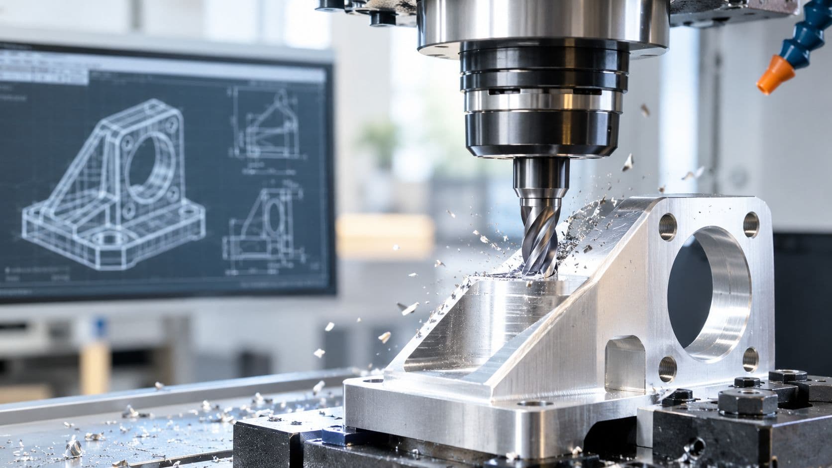
Turning suits parts whose important features share a rotational axis. The workpiece rotates while the tool produces outside diameters, tapers, shoulders, grooves, bores, and threads. Milling holds the workpiece while a rotating cutter creates pockets, flats, irregular contours, and features across multiple faces. Turn-milling combines both approaches when one coordinated setup can machine the rotational body and its off-axis features without reclamping.
Setup choice affects both accuracy and cost. A second clamping operation adds handling, alignment work, inspection, and another opportunity for datum error. That extra setup can outweigh the apparent savings of choosing a simpler machine, especially on prototypes and low-volume runs where setup time is spread across few parts. A turn-mill machine may carry a higher hourly rate, yet still lower unit cost when it removes a separate milling operation.
Standard turning capability is commonly placed around ±0.010 inch, or ±0.25 mm, according to this CNC tolerance capability reference. Tighter results require a rigid setup, suitable tooling, controlled cutting conditions, and more inspection. A turned diameter with tight concentricity may be easier to control than a milled pocket at the same nominal tolerance because the cutting motion follows the rotational axis. The comparison changes when the part needs a precisely located pocket, angled feature, or cross-hole.
| Dimension | CNC Turning | CNC Milling | CNC Turn-Milling |
|---|---|---|---|
| Part geometry | Cylindrical, conical, threaded, and rotational | Prismatic, pocketed, flat, angled, or irregular | Rotational body combined with milled or off-axis features |
| Feature mix | Diameters, faces, grooves, bores, threads | Pockets, slots, flats, contours, drilled patterns | Turned diameters plus flats, slots, cross-holes, or keyways |
| Tolerance behavior | Strong for concentric diameters and axial features | Strong for located features, though tight pockets may need finishing | Reduces re-fixturing and helps preserve feature relationships |
| Batch economics | Efficient when parts share a simple setup | Flexible, though setup and workholding can dominate small jobs | Can repay its higher capability by removing secondary operations |
The machining process guide describes turning as suitable for cylindrical, conical, and threaded forms, while also covering multi-process production. For quoting, compare the complete route, including setup time, secondary operations, inspection, and the number of parts sharing those costs.
Decision shortcut: Start with turning when rotational features dominate. Start with milling when flats, pockets, or located features dominate. Price a turn-mill route when both feature groups must remain accurately related.
Materials Tolerances and Surface Finish You Can Expect
A turned part can look simple on the drawing and behave very differently at the machine. Material choice affects chip control, heat, tool wear, clamping, and the dimensional stability the shop can hold. The right tolerance and finish therefore depend on both the feature's function and the material being cut.
Aluminum such as 6061 and 7075 generally cuts readily, but the tool still needs suitable edge preparation and geometry to limit built-up material. Free-machining brass such as C360 often supports clean production cutting. Copper, including C101, can smear or generate heat when the tool and feeds do not match the cut.
303 stainless is often selected when machinability matters. 316 stainless demands more attention to heat, work hardening, and tool wear. POM, sometimes specified as Delrin, and ABS are common engineering plastics, yet their lower stiffness and thermal response change how the operator clamps, cuts, and inspects the part.
Put the tolerance on the feature that controls assembly or performance, rather than applying a tight limit to every dimension. A general turning capability may sit around ±0.010 inch, or ±0.25 mm. Tighter results depend on rigidity, tooling, workholding, temperature control, and a stable setup. They can also increase cycle time, tool wear, measurement work, and scrap risk. For prototypes and low-volume runs, setup and inspection effort may affect unit cost more than the cutting time itself.
Match finish requirements to function
A sharp, well-supported tool can produce a smooth turned surface, but the result also depends on material, nose radius, feed, tool condition, vibration, and cut direction. Specify texture according to what the surface must do. A locating diameter may need controlled size and form, while a sealing surface may require a defined roughness and measurement method. A cosmetic finish alone does not confirm either requirement.
| Material | Standard Tolerance | Tight Tolerance Achievable | Typical Ra | Machinability Note |
|---|---|---|---|---|
| 6061 aluminum | Drawing dependent | Requires controlled tooling and setup | Application dependent | Generally responsive to turning, with chip and built-up-edge control still important |
| C360 brass | Drawing dependent | Suitable for controlled precision work | Application dependent | Free-machining behavior can support clean chip formation |
| 303 stainless | Drawing dependent | Requires attention to rigidity and tool wear | Application dependent | Often selected when machinability is important |
| 316 stainless | Drawing dependent | More demanding process control | Application dependent | Heat, work hardening, and wear can narrow the process window |
| C101 copper | Drawing dependent | Requires material-specific parameters | Application dependent | Can smear or generate heat if cutting conditions are poorly matched |
| POM and ABS | Drawing dependent | Requires stable workholding and inspection | Application dependent | Thermal and stiffness effects can influence dimensional results |
Finishing operations such as bead blasting, anodizing, plating, or light polishing can add appearance or protection after machining. They may also change dimensions, edges, and surface texture. Include their allowance in the process plan and identify the surfaces that remain functionally critical. For texture specifications, use this surface roughness chart to align the drawing requirement with the shop's measurement method.
Design for Manufacturability Tips That Save Real Money
A drawing can be technically achievable and still be expensive to make. The most useful DFM review asks which features consume setup time, require special tools, create inspection risk, or force the shop away from standard stock and workholding.
Hold tolerance where the part needs it
Mark the diameters, bores, shoulders, and positional relationships that control assembly or performance. Let noncritical dimensions use a sensible general tolerance. Each tight callout can require a dedicated tool strategy, closer offset management, additional inspection, or a more cautious finishing pass.
A tolerance should express design intent, not machine anxiety. The broader principles in this DFM guide help engineers review requirements before the drawing reaches purchasing.
Design around ordinary tools
- Use standard radii: Sharp internal corners force a small tool into a difficult cut. A radius compatible with a standard insert or boring bar usually improves rigidity and reduces slow finishing work.
- Choose stock intelligently: A bar diameter close to the finished envelope reduces waste and cutting time. It also avoids awkward workholding solutions for a part that doesn't fit ordinary jaws or collets.
- Keep threads conventional: Common UNC, UNF, and ISO thread forms are easier to program, gauge, and replace than unusual profiles. Add thread relief when the thread must run cleanly into a shoulder.
- Avoid extreme slenderness: Long, thin features can vibrate or deflect under cutting pressure. Supporting the work with a tailstock, steady rest, or subspindle adds complexity, so a shorter or better-supported design often quotes more cleanly.
- Question every groove and undercut: A groove may be necessary for a retaining ring, seal, or tool exit. If it has no functional purpose, it still adds a tool change, chip-control problem, and measurement task.

A useful design review question: Which feature would the operator be most likely to explain before quoting the part? That feature probably deserves a manufacturability discussion.
Consistent wall thickness also matters for thin sleeves and hollow parts. Uneven sections can distort during machining or finishing, especially when the workholding force is high. A machinist can compensate with jaws, boring techniques, or multiple operations, but those choices carry cost and schedule consequences.
Lead Times Cost and When Turning Makes Sense for Low Volumes
A prototype order can have a short cutting cycle and still carry a high unit price. Programming, material preparation, workholding, tool loading, first-part inspection, deburring, and finishing happen before or after the tool removes most of the material. With only a few parts, these fixed tasks spread across a small quantity. That is why low-volume turning should be quoted by total process effort, not cutting time alone.
The CNC turning center market reached $7.4 billion in 2025 and is projected to reach $12.8 billion by 2034. Job shops represented about 33.6% of global revenue, according to this CNC turning center market report. The figures point to a market serving prototypes, mixed-part work, repeat orders, and mass production. A useful quote therefore separates machine time from changeovers, inspection, and scheduling.
Setup is the economic hinge
For a prototype run, preparation may take longer than cutting each individual part. Similar parts can share chuck jaws, tools, programs, and inspection methods, allowing setup work to spread across a part family. Unrelated parts require separate preparation, and each new setup recreates much of that effort.
Automation stations and connected controls are being adopted to reduce setup time by 15 to 20 percent, as noted in the same CNC turning center market report. The reduction will vary by machine, process, and job. Its practical meaning is straightforward: changeover efficiency strongly affects small-batch economics.
| Volume tier | Quantity range | Raw turning lead time | Machined-only delivery | Fully finished delivery |
|---|---|---|---|---|
| Prototype | 1 to 50 parts | Often driven by programming and setup | Depends on inspection and queue | Add outside finishing coordination when required |
| Low-volume production | 50 to 5,000 parts | Driven by material, setup, and scheduling | Depends on repeatability and capacity | Add finishing, inspection, and logistics time |
Turning usually suits low-volume parts with strong rotational symmetry because the workholding and tool path remain direct. Milling becomes more practical when the part carries extensive pockets, flats, or irregular features. Turn-milling can preserve feature relationships when both operations are substantial, provided the machine and tooling support that approach. For quantities below five, one setup can dominate the economics even when turning is geometrically appropriate.
An online platform or partner such as FIRMFG can provide rapid CNC turning quotes, online DFM feedback, instant pricing, and prototype turned-part lead times as short as three business days, according to its service information. Use that estimate for comparison, then confirm material, tolerances, surface finish, inspection, and outside processing before committing to a schedule.
Key Takeaways Before You Quote Your Next Turned Part
Before sending an RFQ, read the drawing as a process plan. A machine may produce the nominal shape, yet the quote can change sharply once workholding, inspection, and finishing enter the job.
- Identify the motion: CNC turning removes material while the workpiece rotates against a cutting tool. Advanced turning centers may add live tooling for drilling, tapping, and milling features.
- Classify the geometry: Strong rotational symmetry usually favors turning. Pockets, broad flats, and irregular contours often favor milling. A part that needs both may justify turn-milling, especially when one setup helps preserve feature relationships.
- Separate functional tolerances: A general turning capability is commonly around ±0.010 inch, or ±0.25 mm, as noted earlier. Tighter requirements need a clear functional reason, tighter process control, and more inspection. Every added tolerance target can increase unit cost, particularly when setup and verification time are spread across a small batch.
- Choose machinable materials: Aluminum 6061, C360 brass, and 303 stainless are common turning choices. Copper, 316 stainless, POM, and ABS may also work, but tooling and cutting conditions must match the material.
- Review the form: Favor standard stock sizes, practical radii, adequate thread relief, supported slender features, and consistent wall sections. Avoid undercuts, deep grooves, and unusual threads unless the function requires them.
- Price the setup: For prototypes and mixed low-volume work, setup, tooling, inspection, and finishing may cost more than spindle cutting time. Ask how the shop will hold the part, establish datums, inspect critical features, and repeat the process later.
A useful RFQ includes the 3D model, drawing, material and stock preference, quantity, critical tolerances, surface requirements, thread details, finish, inspection expectations, and delivery target. This lets the shop compare turning, milling, and turn-milling by the complete workflow.
For a turned prototype or low-volume part, FIRMFG offers CNC turning, broader CNC machining, finishing support, and DFM feedback. Upload the drawing and model, then ask which setup, inspection, and finishing decisions affect the quote.