CNC Rapid Prototyping: The Complete Engineering Guide
Simple CNC prototypes can ship in 1–3 days, while complex 5-axis parts with demanding finishing can take 7–14 days. The actual timeline depends on geometry, setups, inspection, finishing, and logistics, not on the phrase “rapid prototype” alone.
That distinction matters when a hardware team is holding a design review around an empty fixture. The CAD model is complete, the test plan is waiting, and a missed prototype delivery threatens the next milestone. A supplier may quote a fast machining time, yet the part can still arrive late because the RFQ sat in review, programming took longer than expected, inspection found an issue, or shipping added several days.
CNC rapid prototyping works best when you need a part that behaves like an engineered component, not merely a model that resembles one. It gives you a practical route from CAD to metal or engineering plastic without committing to injection-molding tooling before the design has survived fit, function, and assembly checks.
Table of Contents
CNC Machining vs Other Prototyping Methods- A practical process matrix
Tolerances Materials and Surface Finishing- Select material by the question being tested
Design for Manufacturability and Cost Trade-offs- Four changes that usually help
From CAD File to Shipped Parts- The timeline starts at the RFQ
How to Choose a CNC Prototyping Supplier- Audit the supplier before the order
Moving from Prototype to Production
What Is CNC Rapid Prototyping
A digital housing can look finished while the first physical assembly still exposes misaligned inserts, flexing brackets, or interfering machined faces. CNC rapid prototyping gives engineers evidence from the material, geometry, and interfaces that will affect the working product.
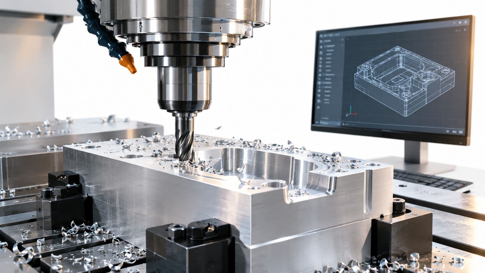
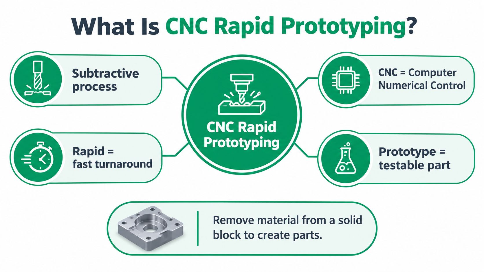
The process is subtractive. A computer-controlled mill or lathe removes material from a solid block of metal or plastic until the part matches the CAD model. Because it uses production-grade stock and does not require a mold, manufacturers can often make functional samples in days rather than weeks.
Why engineers use it before tooling
Injection molding usually requires mold design, fabrication, and qualification before a representative molded part is available. CNC machining removes that tooling dependency. The schedule instead depends on part geometry, tool access, number of setups, inspection requirements, and finishing.
Those variables affect the whole delivery path, not only cutting time. An RFQ may require review, programming may expose access problems, inspection may identify a deviation, and finishing or shipping may add calendar time. A useful quote separates machining time from total delivery time.
CNC also supports more than one-off validation. The same general process can produce low-volume production parts, bridge components, fixtures, and pilot assemblies while keeping material and feature behavior close to later manufacturing conditions. An industry analysis estimated outsourced prototyping and low-volume production activity across the United States, European Union, and Japan at about $20 billion, with roughly 54% of in-scope prototyping activity outsourced, as reported in this industry analysis of outsourced prototyping and low-volume production.
What rapid actually means
“Rapid” describes a shortened route to a usable part, not a fixed schedule. Benchmark guidance lists simple expedited parts at 1–3 days, standard parts at 5–7 days, and complex parts involving multiple setups, harder alloys, or cosmetic finishing at 7–14 days, according to this CNC rapid prototyping lead-time guidance.
For a broader introduction to the development workflow, see this guide to rapid prototyping. Choose the process and supplier around the risk the prototype must answer, then confirm each timeline stage before placing the order.
CNC Machining vs Other Prototyping Methods
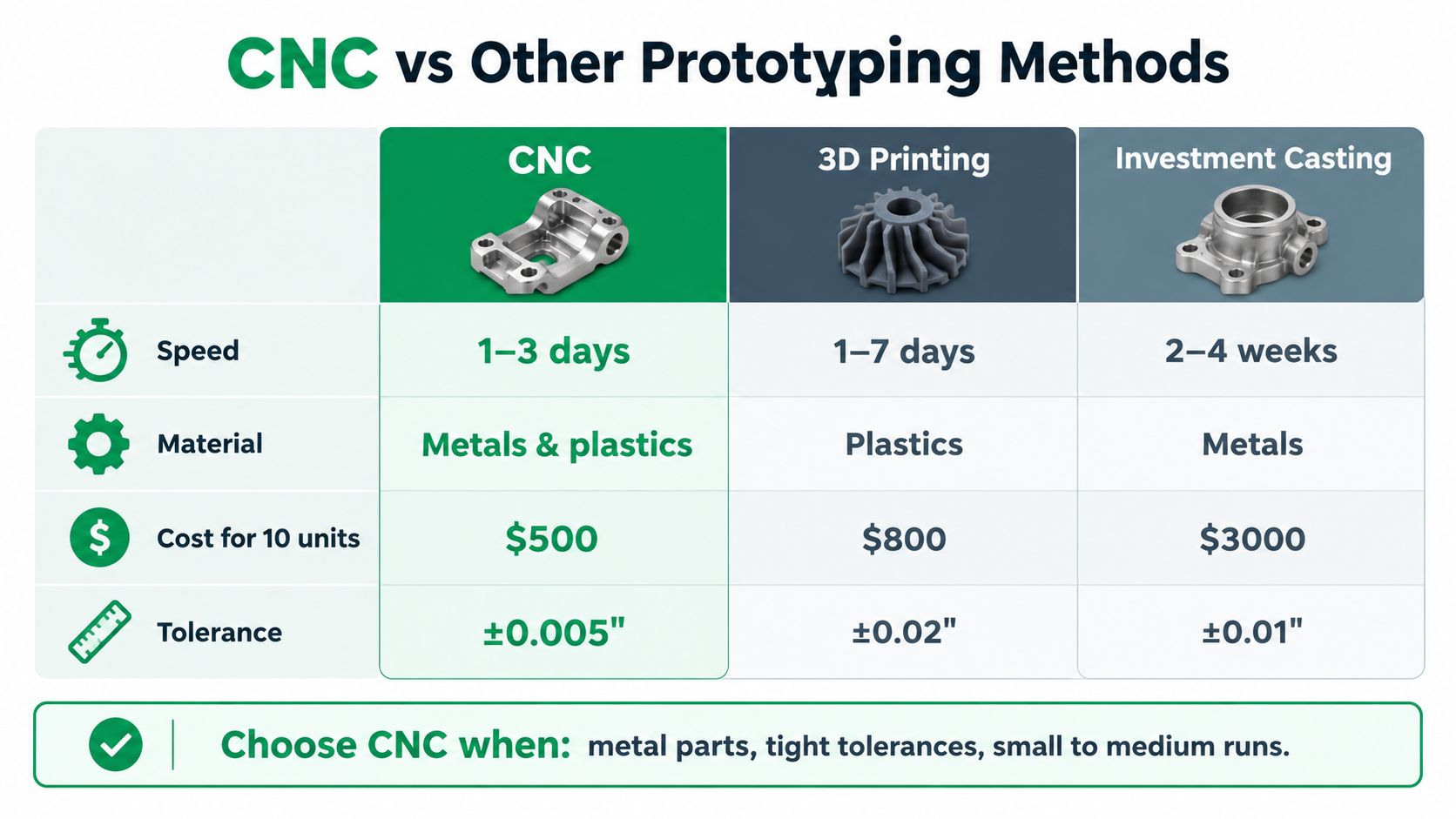
The right prototype process depends on the risk you're trying to retire. A printed model may answer a packaging question quickly, while a CNC-machined aluminum part can answer whether a threaded joint, bearing seat, or load-bearing interface works under realistic conditions.
CNC starts with dense stock and cuts away what isn't needed. SLA and SLS build parts layer by layer, which gives them an advantage for complex internal passages, hollow forms, and early design exploration. Investment casting and urethane vacuum casting can make sense when a project needs repeated replicas, an appearance model, or a route closer to a cast or molded outcome.
A practical process matrix
| Evaluation point | CNC machining | 3D printing | Casting and vacuum casting |
|---|---|---|---|
| Material behavior | Metals and engineering plastics with production-relevant behavior | Strong choice for selected polymers and complex forms | Useful when cast or molded appearance and replication matter |
| Geometry | Excellent for accessible machined features, less suitable for closed internal structures | Strong for intricate internal geometry and fast design changes | Depends on pattern, mold, and casting constraints |
| Surface condition | Machined surfaces and specified secondary finishes are available | Layer marks or post-processing may affect the result | Can reproduce appearance well, with process-specific limitations |
| Functional validation | Strong choice for interfaces, loads, threads, and tolerance-critical features | Useful when geometry is the main uncertainty | Useful when the final material or visual result is closer to a cast or molded part |
| Cost logic | Setup and machining effort dominate at low quantities | Digital setup is fast, with cost tied to material and build effort | Pattern, mold, or tooling work affects economics |
A CNC part is usually the safer choice when the prototype must survive meaningful mechanical, thermal, or assembly testing. A printed part is often the better first move when the design is changing rapidly and the immediate question concerns shape or internal layout rather than final material performance.
Process rule: Choose the process according to failure risk. Use CNC for interfaces and load paths, additive methods for uncertain geometry, and a hybrid route when the project has both problems.
Market research reflects that demand is not limited to mature production programs. One market report valued global CNC machining services at $93.4 billion in 2025 and projected $174.6 billion by 2034, while identifying prototyping as the fastest-growing application segment at an 8.6% CAGR and about 28.9% share in 2025, according to this CNC machining services market analysis. Those figures describe a broad market, but they support a practical observation: prototyping is now integrated into mainstream machining supply, not treated as an isolated workshop activity.
Tolerances Materials and Surface Finishing
A prototype can pass a fit check and still fail the test that matters. Set the specification from the intended test first. For a form check, production-level control on every surface adds cost without improving the decision. For a mating part, seal, bearing support, or functional test, define critical dimensions, datums, and inspection expectations on the drawing.
A capable CNC shop may hold quoted tolerances around ±0.02–0.05 mm, but that range does not apply automatically to every feature. Small holes, deep pockets, thin walls, difficult materials, and multiple setups all increase variation. Post-machining finishing can introduce another control point, so review the tolerance and finish together. This complete guide to CNC machining tolerances provides further guidance on feature control and drawing interpretation.
Select material by the question being tested
Aluminum 6061 suits lightweight brackets, housings, fixtures, and general mechanical validation. It machines cleanly and gives useful evidence about stiffness, threads, and assembly behavior.
Choose stainless steel 316 when corrosion resistance or a closer representation of a durable metal component matters. It usually requires more careful tooling and cutting conditions than aluminum.
Titanium fits designs driven by low mass, high strength, or demanding environmental performance. Machining difficulty rises with it, so reserve tight control for dimensions tied to the test and remove features that do not contribute to the evaluation.
For plastics, ABS supports general housings and fit checks. Polycarbonate is better suited to impact resistance and designs where transparency affects the evaluation. PEEK belongs in prototypes that must represent a demanding engineering polymer, provided the supplier understands its machining behavior and can control the process. Machined plastic also exposes weight, fit, thread behavior, and handling characteristics that a metal substitute can conceal.
Finishing changes function
Finishing affects more than appearance. Anodizing can protect aluminum surfaces and change their visual result. Powder coating adds a durable coated surface to brackets and enclosures. Bead blasting changes texture and can create a more uniform appearance, while passivation supports corrosion-resistance requirements for stainless steel.
Specify the finish before requesting a quote. Masking, inspection, handling, color expectations, and delivery coordination all depend on it. The same applies to deburring, edge breaks, plating, polishing, and marking. “Prototype finish” alone leaves too much open for the supplier to schedule and price accurately.
Keep the drawing practical. Identify datums, mark critical-to-function dimensions, define surface requirements where they affect performance, and avoid applying tight control to a non-critical exterior face. A supplier's quoted lead time is only meaningful when programming, inspection, secondary finishing, and shipping requirements are defined with the part.
Design for Manufacturability and Cost Trade-offs
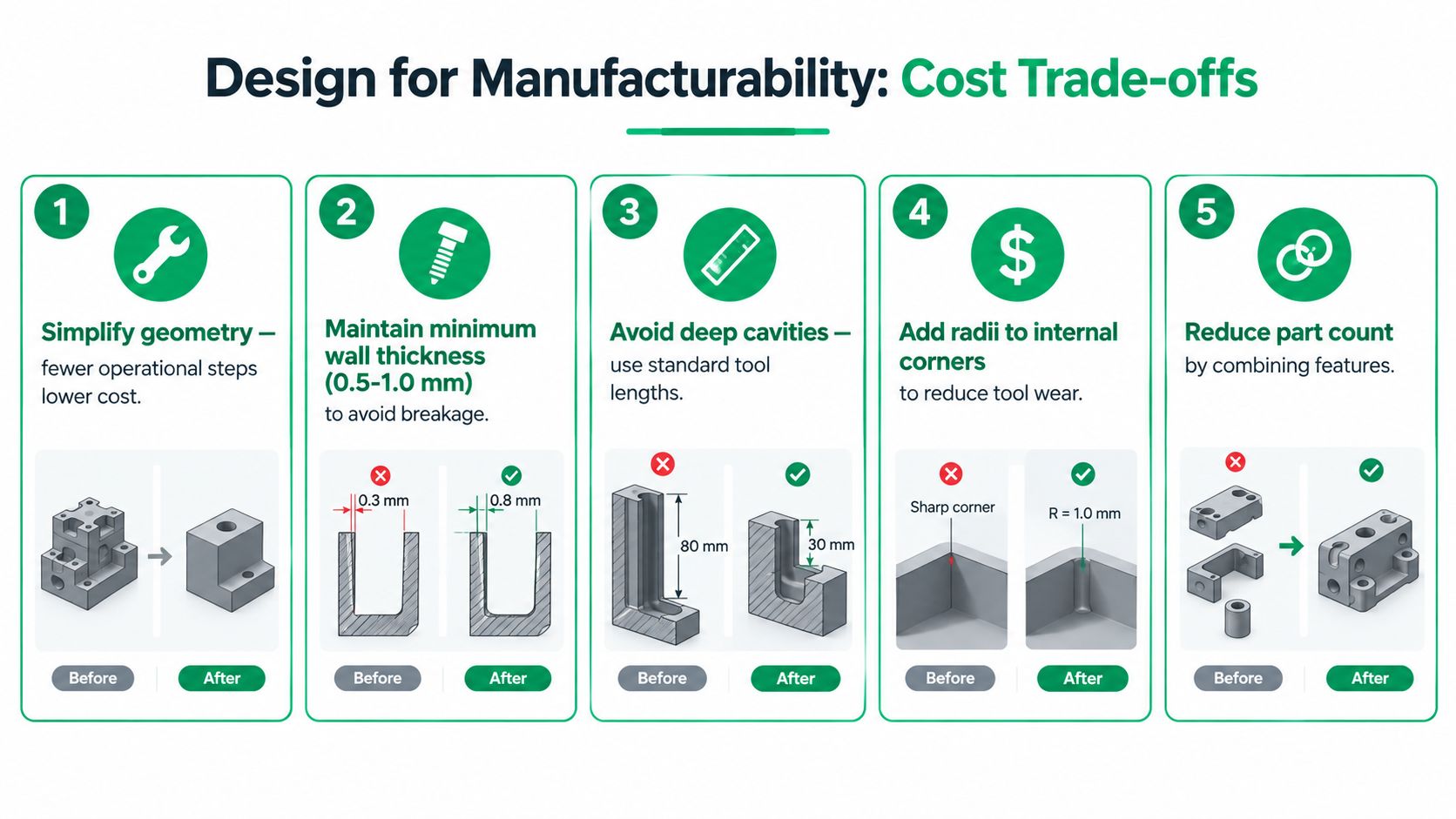
A part can pass the design review and still become expensive at the machine. The usual causes are limited tool access, unstable workholding, repeated re-fixturing, or inspection requirements spread across every feature. Design for manufacturability keeps useful engineering functions intact while making the part easier to cut, hold, and verify.
Cost often hides in details that look simple in CAD. A pocket may require an awkward tool approach. A thin wall can vibrate or distort, forcing slower cutting conditions. A part with several machined faces may need multiple orientations, each adding alignment work and another opportunity for accumulated error. Tight tolerances on nonfunctional surfaces also increase programming and inspection effort without improving the prototype.
Four changes that usually help
- Reduce setups. Arrange reference surfaces and access directions so more work can be completed from fewer clamping orientations. This improves repeatability and reduces setup labor.
- Use consistent internal radii. Milling tools leave a radius in internal corners, so a mathematically sharp corner requires a special process or additional finishing. Radii sized for standard end mills can reduce machining time by about 35%, according to this engineering guidance on CNC design for manufacturability. Consistent radii also simplify tool selection and CAM programming.
- Control cavity depth. Where the design permits, keep cavity depth near three times the feature width. Deeper, narrower cavities increase tool deflection, vibration, chip evacuation problems, and finishing effort. If the depth serves no test or functional requirement, changing the geometry may save more time than adjusting cutting parameters.
- Reserve tight tolerances. Apply close control to interfaces, bearing seats, sealing surfaces, and test-critical dimensions. Use broader tolerances on features that do not affect performance. This keeps inspection focused and prevents the entire component from being treated as a precision feature.
Complexity has a nonlinear price
A five-axis toolpath is useful for angled surfaces and can reduce some fixturing, but it does not automatically lower total cost. Programming, simulation, workholding, and inspection may become more involved. The cited engineering reference reports 200–500% higher programming and machining effort for complex five-axis features compared with simpler three-axis features, depending on the comparison. The same reference also identifies the machining-time effect of standard-radius design, so both trade-offs are covered by one DFM engineering reference.
Ask whether each difficult feature answers a real product question. If it does, retain it and select a machine and inspection plan that support the requirement. If it does not, simplify the geometry before the RFQ. That decision usually saves more than negotiating the hourly rate after the design is fixed.
From CAD File to Shipped Parts
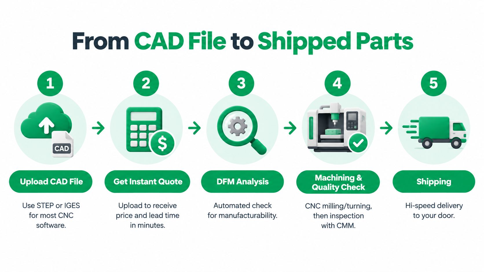
A prototype order starts before the machine runs. The supplier must understand the model, drawing, material, finish, quantity, inspection requirement, and delivery destination well enough to identify the actual work content.
The timeline starts at the RFQ
Send a solid CAD format such as STEP or IGES for machining review, along with a drawing that identifies datums, critical dimensions, threads, surface requirements, material, and finish. An STL file describes a faceted surface and is more useful for additive manufacturing than for a precision CNC quote.
The RFQ review should answer several questions:
- Material: Is the specified alloy or plastic available and suitable for the test?
- Access: Can standard tools reach every feature?
- Tolerance: Which dimensions require formal inspection?
- Finish: Does anodizing, coating, blasting, passivation, or plating follow machining?
- Quantity: Can the supplier combine parts in one setup or nest them efficiently?
Programming begins after that review. A simple three-axis part with accessible faces may move quickly, while a part requiring multiple orientations, custom workholding, or five-axis motion needs more CAM planning and simulation.
Machining is only one stage
After setup, the machine removes stock through roughing, semi-finishing, and finishing operations. The supplier may use milling, turning, or a combination of processes, depending on the geometry. Parts then need deburring and inspection against the drawing. A coordinate measuring machine, calibrated gauges, or targeted dimensional checks can verify the features that matter to assembly and testing.
Finishing and packaging follow inspection. Protect machined faces, threaded holes, cosmetic surfaces, and sharp edges before transit. Overseas shipping can add several days, and the difference between a quoted machining duration and the date at your receiving dock can be substantial. Independent guidance notes that a part can move from 3–5 business days to 7–12 days once export logistics are included, as discussed in this prototype machining lead-time guide.
For a detailed process reference, see this CNC machining process guide. Ask suppliers to show the schedule as RFQ review, programming, setup, machining, inspection, finishing, and transit. That breakdown exposes the bottleneck before it becomes a missed milestone.
How to Choose a CNC Prototyping Supplier
The lowest quote isn't necessarily the lowest project cost. A supplier that misses a tolerance, outsources finishing without controlling the handoff, or gives an optimistic delivery date can create another design loop and erase the initial price advantage.
Start by matching capability to the part. Ask whether the shop runs the machine types your design needs, including three-axis, four-axis, and five-axis milling, turning, micro machining, or wire EDM. You don't need maximum capability for every prototype, but you do need the right access strategy for the features on your drawing.
Audit the supplier before the order
Use a direct evaluation rather than relying on a polished website:
- Quality system: Look for relevant frameworks such as ISO 9001, ISO 13485 for medical work, or IATF 16949 capability for automotive programs.
- Inspection resources: Confirm whether the supplier uses CMM measurement, calibrated gauges, documented first-article checks, and traceable inspection records.
- Response discipline: Ask how quickly the team reviews files, identifies DFM risks, and separates machining time from shipping time.
- Order flexibility: A no-MOQ policy can matter when you need only a few validation parts or want to compare design revisions without buying excess stock.
- Finishing control: In-house anodizing, powder coating, plating, bead blasting, or passivation reduces the number of uncontrolled external handoffs.
- Technical communication: A useful supplier explains why a feature is difficult and offers a workable alternative instead of rejecting the file.
Request DFM feedback before placing the order. The response should mention tool access, setups, thin walls, cavity depth, tolerance conflicts, and inspection strategy. Generic approval language tells you little.
For example, FIRMFG combines CNC milling and turning with additive manufacturing, sheet metal, molding, vacuum casting, finishing, inspection, and DFM support. That kind of process breadth can help teams keep design validation and low-volume supply within one coordinated workflow, but you should still evaluate its response against your drawing and test requirements.
A supplier earns trust before cutting metal by making the risks visible in the quote.
Moving from Prototype to Production
A successful prototype doesn't automatically become a production part. It gives the team evidence, and that evidence should update the CAD model, drawing, material decision, inspection plan, and process choice before the next build.
CNC often carries naturally into low-volume production and bridge manufacturing because the process doesn't require injection-molding tooling. It can support pilot quantities, spare parts, fixtures, and early customer units while the design continues to mature. The same supplier may also produce a small molded run through rapid tooling once demand and geometry justify that investment.
Keep CNC in the workflow when the quantity remains limited, the design is still changing, or the part has features that would make tooling risky. Move toward hard tooling when demand is high enough for tooling economics to outweigh machining flexibility and when the design has stabilized. The exact break-even point depends on geometry, material, tooling complexity, cycle requirements, and part price, so don't use a universal quantity rule without a quote comparison.
A partner with CNC, 3D printing, sheet metal, molding, casting, and finishing capabilities can also reduce transfer risk during NPI. The benefit isn't just convenience. One technical team can preserve material intent, critical dimensions, cosmetic requirements, and inspection logic as the product moves from exploratory prototypes to pilot builds.
CNC rapid prototyping has become a strategic engineering tool because it connects design decisions to physical evidence quickly. Use it when the risk is functional performance, interface accuracy, or production-relevant material behavior. Use additive or hybrid methods when geometry remains uncertain, then machine the features that must prove themselves under realistic conditions.
FIRMFG supports CNC rapid prototyping and precision machining for metal and plastic parts, alongside 3D printing, sheet metal, molding, casting, finishing, inspection, and DFM review. Upload your CAD files and requirements through FIRMFG to request a practical process recommendation and quote for your next validation build.