What Is Rapid Prototyping: Methods & Benefits for 2026
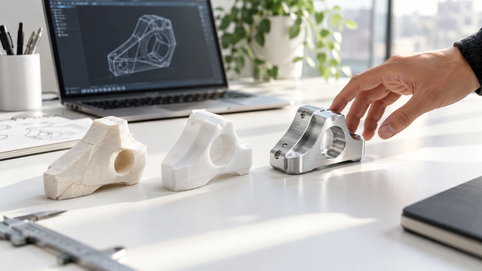
You've frozen the CAD model, scheduled the design review, and discovered that the prototype supplier needs weeks before the team can test a simple interface. By the time the part arrives, the next design decision is already overdue. A slow prototype cycle doesn't just delay fabrication. It delays feedback, hides manufacturability problems, and increases the chance that an expensive tooling or production decision will be based on an untested design.
Rapid prototyping gives manufacturing teams a faster way to turn digital designs into physical evidence. The important question, however, isn't only how quickly a machine can make a part. It's how fast your team can submit a design, select a suitable process, receive a usable component, inspect it, learn from it, and apply that learning to the next revision. That end-to-end lead time is where many projects lose momentum.
Table of Contents
- Introduction to Rapid Prototyping for Manufacturing Teams
- Understanding the Key Concepts
From manual models to digital fabrication
What makes the process rapid
Comparing Methods and Materials- CNC machining for functional accuracy
How to Evaluate Prototyping Choices- Key Drivers of Lead Time
Use Cases for Rapid Prototyping Methods- Fit and assembly checks
Prototyping to Production Workflow with DFM- Start with a manufacturing-ready submission
How FIRMFG Solves Prototyping Challenges
Conclusion and Next Steps
Introduction to Rapid Prototyping for Manufacturing Teams
A mechanical engineering team might need to verify a connector fit, check whether a housing feels comfortable, and test a mounting bracket under working conditions. A low-detail visual model can answer the ergonomic question, but it may say little about thread strength or dimensional stability. A printed plastic part may reveal an interference issue, while a machined metal component may be necessary to evaluate a loaded joint.
This is why rapid prototyping is better understood as a validation strategy, not a single machine or material. Teams use additive manufacturing, CNC machining, molding, casting, sheet metal fabrication, and finishing according to the question each prototype must answer. A useful prototype makes uncertainty visible before the project reaches a more expensive manufacturing stage.
The industry's commercial scale reflects that demand. Recent market research estimates the global rapid prototyping market at USD 4.83 billion in 2026, with the estimate tied to demand for faster product development and short-run manufacturing, as reported in this rapid prototyping market analysis.
A practical overview of applications can be found in FIRMFG's rapid prototyping examples, but the central principle is simple: make the right physical part early enough for the team to act on what it reveals.
Understanding the Key Concepts
Rapid prototyping is the use of digitally driven manufacturing processes to produce physical parts, models, or assemblies for design validation and iteration. The input is usually a 3D CAD file. The output might be a visual model, a fit-check component, a functional assembly, or a low-volume part made with a production-representative material.
The word “rapid” refers to the development loop, not a universal promise of same-day production. A prototype is useful only when it arrives in time for a decision and has enough fidelity to answer the engineering question. A fast but dimensionally unsuitable part can create more confusion than a slower, properly specified component.

From manual models to digital fabrication
Before modern rapid prototyping, product teams often depended on manual model-making, physical tooling, and specialist model shops. Those methods could produce valuable results, but each design change might require substantial rework. Digital fabrication changed the relationship between a CAD revision and a physical part.
A brief historical sequence explains the shift:
- 1980: Hideo Kodama developed an early UV-cured polymer rapid prototyping approach.
- 1986: Charles Hull patented stereolithography, commonly called SLA, the first commercially viable 3D printing method.
- 1987 or 1988: Hull's company released the SLA-1, helping launch the modern era of rapid prototyping.
This sequence is documented in the history of rapid prototyping. The significance goes beyond the dates. Rapid prototyping began as an industrial response to slow design validation, not as a consumer hobby. It established the technical foundation for today's iterative workflows in engineering, product design, and low-volume manufacturing.
What makes the process rapid
A typical workflow starts with a CAD review, followed by process selection, material selection, fabrication, finishing, inspection, and feedback. The team then updates the design or approves it for the next development stage.
That sequence also exposes a common misunderstanding. A printer or CNC machine may complete its core operation quickly, while file preparation, material availability, support removal, surface finishing, dimensional inspection, shipping, and internal approval add time around the operation. The manufacturing process is only one part of the delivery cycle.
Practical rule: Define success before fabrication. Decide whether the prototype must prove appearance, fit, movement, load behavior, sealing, assembly, or manufacturability.
Comparing Methods and Materials
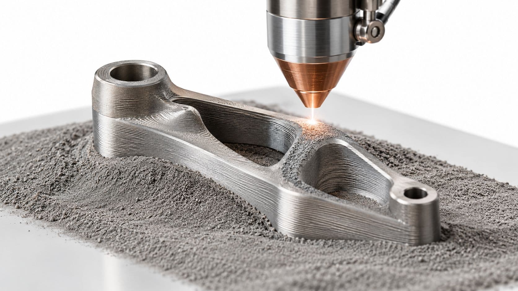
No prototyping process is ideal for every engineering question. CNC machining removes material from a block, which makes it suitable for accurate metal and plastic parts with functional surfaces. Additive manufacturing builds parts layer by layer, enabling quick geometry changes and shapes that may be difficult to machine. Molding and casting can provide a closer approximation of production materials and appearance when a project needs multiple representative parts.

CNC machining for functional accuracy
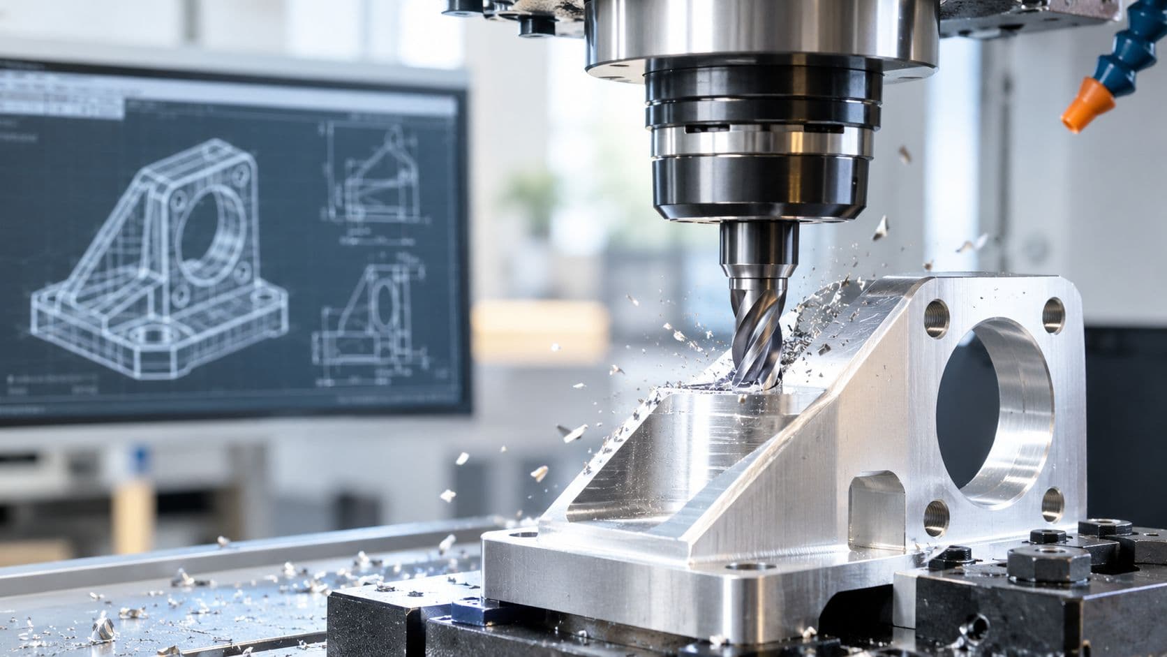
CNC milling and turning work well for components that must withstand mechanical loads, mate with other parts, or use production-grade metals. Aluminum is often useful for lightweight brackets, housings, and heat-related components. Stainless steel and other steels suit parts where wear resistance, stiffness, or durability matters. Engineering plastics can support electrical isolation, low-friction interfaces, and lightweight assemblies.
CNC can also produce holes, threads, sealing faces, pockets, and other features that require controlled geometry. Wire EDM is useful for intricate conductive parts and difficult internal profiles, while multi-axis machining can reduce repositioning for complex components.
For a direct discussion of process trade-offs, see this comparison of CNC machining and 3D printing.
SLA, SLS, and FDM for additive iteration
SLA cures liquid resin with light. It's a strong choice for smooth visual models, fine features, presentation parts, and master patterns. The material and post-processing requirements mean that an SLA part shouldn't automatically be treated as equivalent to an injection-molded production component.
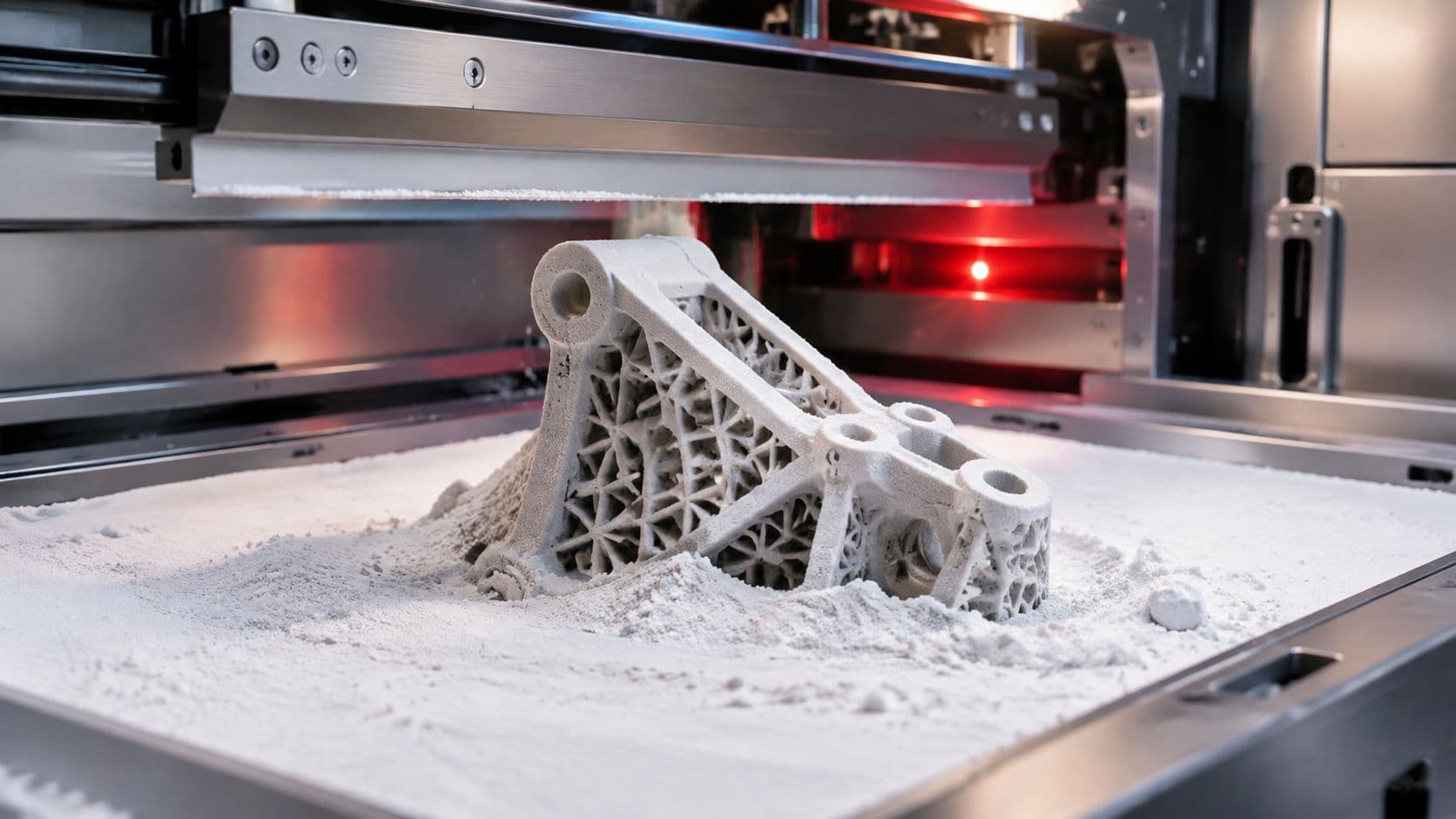
SLS fuses polymer powder with a laser and can produce complex forms without the same support structures associated with some other additive methods. It suits functional plastic prototypes where geometry, durability, and freedom of form matter.
FDM extrudes thermoplastic filament. It's often selected for quick, economical iterations, fixtures, basic housings, and early functional checks. Layer orientation, surface texture, and process settings affect the final result, so the team should define which loads and interfaces the part must withstand.
Molding and casting for production-representative parts
Vacuum casting uses a silicone mold and polyurethane resin to create small batches of appearance or functional parts. It can replicate surface details and support bridge builds when a team needs several similar components before committing to production tooling.
Rapid injection tooling becomes relevant when the team needs to evaluate molded geometry, production-like material behavior, or an early batch from the intended process family. It requires more planning than a simple printed prototype, but it can expose molding-specific issues such as difficult material flow, inadequate draft, or unsuitable wall transitions.
The correct material follows the test objective. A visual review may need a smooth resin and cosmetic finishing. A load test may require machined aluminum or a suitable engineering plastic. A sealing test may need production-representative geometry, controlled surfaces, and inspection rather than the fastest available fabrication method.
How to Evaluate Prototyping Choices
A useful comparison starts with four criteria: cost per part, lead time, fidelity, and tolerance control. These measures affect one another. A low-cost process may provide less dimensional confidence, while a highly accurate part may require additional programming, fixturing, inspection, or material expense. A quick fabrication step can still result in a late usable part if finishing or inspection creates a queue.
Begin with the decision the prototype must support. A cosmetic print can answer questions about proportions and appearance. A bearing seat needs a machined component with verified dimensions. A molded enclosure may require a process that reflects molding behavior, because a printed shell will not reveal every production-related issue.
Key Drivers of Lead Time
Practical prototype timelines can range from 24 hours to two weeks, depending on process, complexity, and post-processing requirements, according to this prototyping lead-time guidance. The range is broad because “part complete” can describe very different deliverables. A raw printed component is not equivalent to a deburred, coated, inspected, assembled, and documented part.
The main schedule factors are:
- Design readiness: Unresolved CAD details and late changes delay quoting, process planning, and programming.
- Process selection: A supplier may need to redirect a part from printing to machining when the test requires tighter dimensional control.
- Material availability: The specified alloy, resin, or engineering plastic can change the production sequence.
- Finishing: Anodizing, bead blasting, coating, polishing, and similar treatments add operations after fabrication.
- Inspection: Critical interfaces need measurement and reporting before engineers can rely on the results.
- Handoffs: Separate suppliers for machining, finishing, and assembly add communication, transport, and scheduling steps.
The shortest machine cycle is therefore only one part of the schedule. A supplier with machining, finishing, inspection, and other processes under one coordinated workflow can reduce waiting between operations. That matters when a design change requires both a revised part and new DFM feedback. Instead of sending the component through disconnected queues, the team can address manufacturability concerns while the prototype is being prepared.
Dimensional requirements should also guide process selection. Multi-axis CNC can routinely hold approximately ±0.001 to ±0.005 inches, with critical features reaching roughly ±0.0005 inches under suitable fixturing and inspection. Typical 3D printing tolerances are looser, approximately ±0.005 to ±0.015 inches, depending on the process. These ranges are reported in this rapid prototyping tolerance guide.
Rapid prototyping decision matrix
| Process | Cost per Part | Lead Time | Typical Fidelity | Tolerance Range |
|---|---|---|---|---|
| CNC machining | Higher process effort, especially for complex metal geometry | Short to moderate, depending on programming, fixturing, and inspection | High functional fidelity with production-grade materials | Approximately ±0.001 to ±0.005 inches, with critical features near ±0.0005 inches under suitable conditions |
| SLA | Often economical for visual parts and fine details | Short, with post-processing added | Smooth surfaces and detailed cosmetic geometry | Typically process-dependent and looser than precision CNC |
| SLS | Useful for complex functional plastic geometry | Short to moderate, depending on nesting and finishing | Durable plastic forms without conventional support structures | Typically process-dependent and looser than precision CNC |
| FDM | Cost-effective for early iterations and basic functional checks | Short for straightforward parts | Practical geometry with visible layer structure | Approximately ±0.005 to ±0.015 inches for typical 3D printing, depending on process |
| Vacuum casting | Useful for small batches and appearance models | Moderate, because mold creation and casting are separate stages | Close visual replication with selected polyurethane materials | Dependent on mold quality, resin, geometry, and inspection |
For a broader breakdown of project pricing factors, review this guide to rapid prototyping cost. A useful quote compares the complete usable-part timeline, including DFM review, fabrication, finishing, inspection, and handoffs, rather than only the machine's operating time.
Use Cases for Rapid Prototyping Methods
A prototype should answer a defined question. For a bracket, the question may be whether it clears nearby components. For a housing, it may be whether users can grip and operate it. Name the test first, then select the process and material that provide credible evidence.

Fit and assembly checks
For a bracket, enclosure, or mating connector, begin with interference and access. An FDM or SLA part can confirm the overall envelope, hole position, tool access, and assembly sequence. If the interface includes a precision bearing seat, thread, seal, or sliding mechanism, CNC machining provides stronger dimensional evidence.
Test the prototype with surrounding components, not in isolation. A part that looks correct on a screen may collide with a fastener head, require an impractical tool angle, or create an unacceptable tolerance stack after assembly. These checks also reveal whether a feature needs DFM feedback before the next build.
Ergonomic and cosmetic reviews
A product housing, handle, control panel, or wearable component may need human evaluation before functional engineering is complete. SLA can provide a smooth surface and fine visual detail. FDM may suit early shape studies when the team is comparing proportions, grip, reach, or access.
Finishing changes perception. Sanding, painting, bead blasting, anodizing, or other treatments can help reviewers judge the intended appearance. Label cosmetic prototypes clearly, because surface quality alone does not show production readiness.
Functional stress and material checks
A loaded joint, heat-exposed component, or wear interface requires a process and material aligned with its expected use. Machined aluminum or steel may suit parts where stiffness, threads, and contact surfaces matter more than speed. An engineering plastic may suit an electrically isolated component or lightweight mechanism, provided the test conditions match the material's intended behavior.
Pilot and bridge builds
When a team needs multiple representative parts, vacuum casting, rapid tooling, sheet metal fabrication, or low-volume CNC can provide more useful evidence than one-off visual models. Sheet metal prototypes help evaluate brackets, covers, and enclosures because laser cutting, bending, and welding expose bend relief, flange access, fastening, and assembly issues.
The shortest machine time does not always produce the shortest usable-part cycle. FIRMFG can combine processes and coordinate fabrication, finishing, inspection, and DFM feedback, reducing handoffs that otherwise delay design reviews. Ask suppliers to separate fabrication time from total delivery time, then schedule the review around a finished, inspected part rather than an unfinished component waiting for the next operation.
Prototyping to Production Workflow with DFM
Rapid prototyping creates the most value when design for manufacturing, or DFM, enters before the design is treated as final. A prototype can reveal that a part fits poorly. A DFM review can explain why the geometry will be difficult, expensive, or inconsistent to manufacture repeatedly.

Start with a manufacturing-ready submission
The workflow begins with the CAD model, drawings, material requirements, finish specifications, inspection expectations, and assembly context. A supplier can then evaluate whether the geometry suits CNC, additive manufacturing, molding, casting, sheet metal, or a combination of processes.
At this point, engineers should identify wall thickness, inaccessible features, deep pockets, sharp internal corners, draft requirements, datums, threads, and tolerance-critical interfaces. They should also distinguish cosmetic dimensions from functional dimensions. That distinction prevents the team from paying for tight control where it doesn't affect performance.
Use the prototype as a DFM experiment
The first physical build should test more than appearance. Measure the critical features, assemble the part with mating components, inspect surface condition, and document any failure modes. A manufacturability review should then connect each problem to a design response.
For example:
- Wall thickness: Adjust geometry if the selected molding or casting process creates filling, distortion, or cooling concerns.
- Draft angles: Add release-friendly geometry before tooling is designed.
- Tolerance stacks: Check how individual part variation affects the assembled mechanism.
- Tool access: Modify pockets, corners, or fixturing surfaces if machining access is limited.
- Material behavior: Confirm that strength, flexibility, temperature resistance, and finish support the intended use.
- Inspection strategy: Define datums and measurement methods before the part enters a pilot run.
Create approval gates
A disciplined workflow uses explicit decisions rather than informal approval. The team can organize the sequence as follows:
- CAD submission and review: Confirm files, materials, drawings, and test objectives.
- Prototype build: Produce the part using the selected process.
- DFM checkpoint: Review geometry, tolerances, material suitability, and production feasibility.
- Tooling or fixture development: Prepare production aids only after the design addresses identified risks.
- Pilot production: Run a small build that tests the complete manufacturing sequence.
- Quality and process validation: Verify dimensions, finish, assembly, and repeatability.
- Production release: Approve the design and process for the intended manufacturing stage.
Prototyping methods function as de-risking tools because they expose design and manufacturability issues before higher-cost production steps, a point discussed in this review of rapid prototyping applications.
The major lead-time improvement comes from combining these activities intelligently. If machining, additive fabrication, molding, finishing, and inspection happen through disconnected suppliers, each handoff can restart communication and scheduling. A multi-process partner can compare alternatives earlier and keep the feedback loop focused on the next engineering decision.
How FIRMFG Solves Prototyping Challenges
FIRMFG combines CNC machining, 3D printing, sheet metal fabrication, injection molding, vacuum casting, and surface finishing for metal and plastic components. That breadth matters when the correct prototype process changes during development. A team might begin with an SLA housing for form review, move to CNC aluminum for functional testing, then use rapid tooling or vacuum casting for a bridge build.
The company describes more than 15 years of manufacturing experience, 300+ in-house machines, and quality frameworks including ISO 9001 and ISO 13485, with IATF 16949 capability for automotive-related work. Select prototyping services offer 24-hour delivery, while the broader schedule still depends on geometry, material, finishing, inspection, and quantity.
The useful distinction is between machine speed and complete project speed. FIRMFG's integrated workflow can support quoting, DFM feedback, fabrication, finishing, and inspection without requiring the engineering team to coordinate every operation as a separate supplier handoff. That structure can help teams resolve questions about tolerance, material, process suitability, and production transition earlier.
Engineers should still provide clear requirements. Include the CAD files, drawings, critical dimensions, surface finish expectations, material preference, quantity, assembly context, and the test the prototype must pass. A supplier can't select the right process from geometry alone if the part's real purpose is unclear.
Conclusion and Next Steps
Rapid prototyping turns CAD revisions into physical feedback before the design reaches expensive production commitments. The right method depends on the question being tested, the material and performance required, the tolerance target, and the complete lead time from file submission to inspected usable part.
Audit your current prototype cycle and identify delays outside fabrication, including design freezes, material sourcing, finishing, inspection, and supplier handoffs. Set explicit cost, lead-time, fidelity, and tolerance targets for each build. Then request a DFM review before tooling or pilot production so the first production-intent decision reflects real manufacturing constraints.
FIRMFG provides CNC machining, 3D printing, sheet metal, molding, vacuum casting, finishing, and DFM support for rapid prototypes and low-volume builds. Visit FIRMFG to submit your design requirements and discuss a process plan focused on shortening the complete cycle from CAD review to validated parts.