Geometric Tolerancing Runout: Symbols and Callouts
A shaft can pass inspection on the bench and still bind when it reaches the assembly line. The usual cause isn't a bad indicator reading. It's a runout callout that controlled the wrong failure mode, measured from an unstable datum, or was applied to a feature whose function required a different geometric control.
That's why geometric tolerancing runout deserves more attention than a symbol copied into a feature control frame. Circular runout and total runout both relate a surface to a datum axis, but they constrain different geometry and demand different inspection methods. The right choice helps a CNC shop control the variation that affects rotation, sealing, bearing contact, and coaxial engagement. The wrong choice either rejects usable parts or lets a functionally bad part pass.
Table of Contents
- Why Runout Callouts Decide Whether a Shaft Actually Fits
Two shafts can produce the same local reading
Start with the downstream failure
What Runout Means in Geometric Dimensioning and Tolerancing- Read the symbol and frame correctly
Circular Runout vs Total Runout and When to Use Each- Choose the control by the contact pattern
Measuring Runout with Indicators and CMMs on the Shop Floor- Dial indicator setup
Worked Example of a Runout Tolerance Stack on a Mating Shaft and Bore
Common Mistakes When Specifying and Inspecting Runout- Choosing the wrong member of the symbol family
A Practical Checklist for Choosing and Verifying Runout on Your Next Drawing
Why Runout Callouts Decide Whether a Shaft Actually Fits
A ground shaft once arrived at inspection with a circular runout callout of 0.05 mm to datum A-B. The inspector mounted it between centers, rotated it, and recorded a passing full indicator movement at the checked stations. On the bench, the shaft looked acceptable.
It failed at the customer's assembly line.
The shaft journal entered a bearing housing, but the bearing did not track consistently along the journal. The drawing specified circular runout, while the assembly needed the journal to remain coaxial across its working length. Circular runout judged each cross-section independently, so the shaft could show a different center at different stations and still pass every local reading. The resulting mid-shaft wobble created an eccentric condition that the inspection setup never evaluated as one continuous surface.
Shop-floor rule: A passing runout number only proves that the part meets the control written on the drawing. It doesn't prove that the drawing controls the assembly problem.
Two shafts can produce the same local reading
Consider two shafts with identical circular runout readings at the inspected stations. Shaft A keeps its axis consistent from one end to the other. Shaft B has local sections that remain round but drift gradually away from the datum axis. At each individual plane, both shafts can produce the same indicator movement. Across the full journal, however, Shaft B can develop substantially more positional variation.
That difference is the reason total runout exists. Circular runout asks, “How much does this cross-section wobble as the part turns?” Total runout asks, “How much does the entire surface vary while the part rotates and the indicator travels along it?” Those questions lead to different acceptance decisions.
ASME Y14.5 identifies circular runout as an independent cross-section control and total runout as a control on the entire surface. The modern lineage of the standard traces to MIL-STD-8 in 1949, followed by the first ANSI/ASME Y14.5 version in 1973, while ASME Y14.5-2018 updated runout definitions after decades of inspection-oriented wording. These historical changes matter because rotating parts such as shafts, bores, and bearing seats need a functional relationship to an axis, not merely acceptable plus-or-minus dimensions. ASME Y14.5 background and runout history
Start with the downstream failure
Before adding a runout symbol, identify what the mating component experiences. A bearing may contact a localized journal. A seal may follow a continuous diameter. A hub may engage a pilot over its full length. A flange may need a face to remain true as it rotates.
Each situation can justify a different control. Runout isn't a paperwork decoration. It's a compact way to control the combined effect of form and location errors relative to a functional rotation axis, but only when the symbol, datum, tolerance value, and inspection method agree with the assembly.
What Runout Means in Geometric Dimensioning and Tolerancing
Runout is the full indicator movement of a surface as the part rotates 360 degrees about a datum axis. The indicator sees the difference between the highest and lowest measured positions. That value is the measured runout, often reported as FIM.
Runout belongs to the geometric tolerance family defined by ASME Y14.5. The standard distinguishes circular runout, which evaluates one circular cross-section at a time, from total runout, which evaluates the complete surface while the indicator moves along it. ISO 1101 also treats runout as a basic geometric tolerance, with examples commonly representing the zone as two concentric circles in each cross-section. Practical explanation of circular runout and its tolerance zone
Read the symbol and frame correctly
The symbol family is easy to recognize:
- Circular runout uses a single arrow.
- Total runout uses a double arrow.
A basic circular runout frame might be written in plain text as:
circular runout | 0.05 | AOn an engineering drawing, the symbol appears in the first compartment of the feature control frame, followed by the tolerance value and the datum reference. The value defines the permitted indicator movement. The datum reference establishes the axis around which the controlled surface is evaluated.
A more complex datum reference can identify a primary datum and a tertiary datum, with the secondary datum occupying the implied position between them. Don't treat datum order as a formatting detail. It determines how the part is constrained and therefore which axis the inspector establishes.
For a practical overview of feature control frames, datum references, and tolerance zones, use this GD&T practical guide.
Know what geometry the callout reaches
Runout can apply to cylindrical surfaces, circular elements, conical features, and certain flat or curved features constructed from circles. The key distinction is between a circular element and the entire surface.
A circular element is one cross-section perpendicular to the datum axis. Circular runout evaluates that element as the part rotates. A full surface includes the relationship between multiple sections along the feature, which is why total runout can expose variation that local section checks don't see.
ASME Y14.5-2009 identified 14 types of geometric tolerances, with runout remaining one of the core controls. By ASME Y14.5-2018, the standard had moved away from describing runout mainly through dial-indicator language and clarified its application to assemblies. Runout's role among geometric tolerances
Circular Runout vs Total Runout and When to Use Each
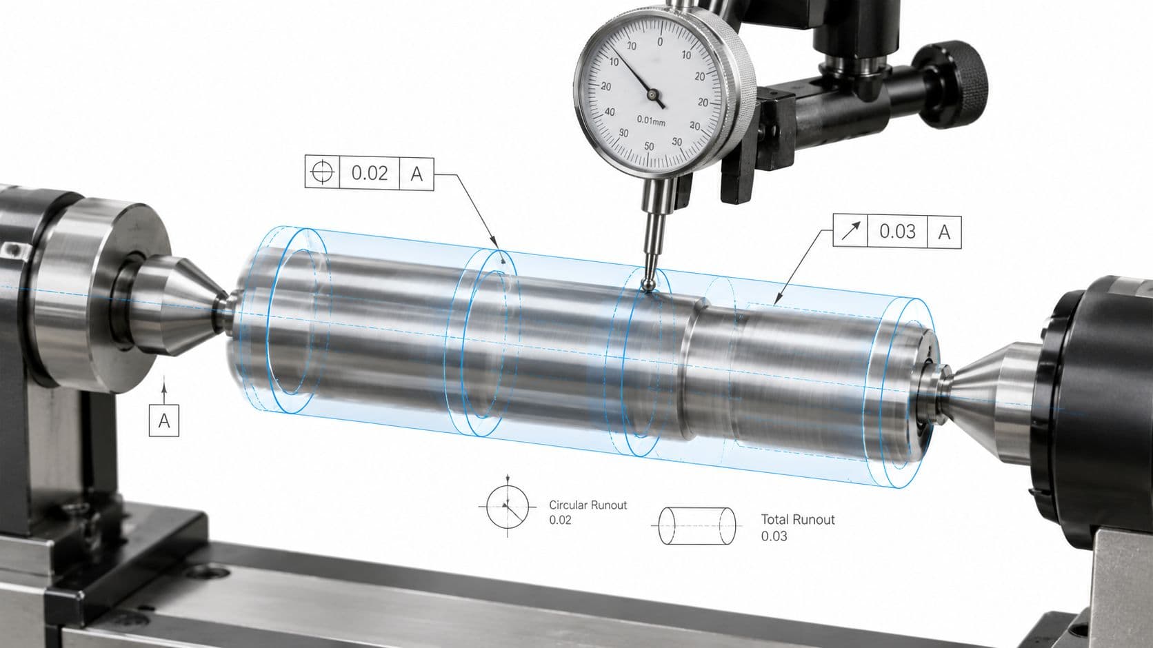
The most useful distinction is geometric, not symbolic. Circular runout creates a separate 2D tolerance zone at each cross-section. Total runout creates one 3D tolerance zone over the full surface.
For circular runout, imagine two concentric circles in a plane perpendicular to the datum axis. The radial distance between those circles equals the stated tolerance. Each cross-section gets judged independently. A local lobe, a station of grind chatter, or a localized eccentric condition can fail the section, while variation between sections can remain outside the control's scope.
Total runout uses two coaxial cylinders separated by the specified tolerance. The part rotates about the datum axis while the indicator traverses axially. The entire surface must remain inside the zone. That makes total runout sensitive to taper, straightness variation, progressive profile drift, and eccentricity across the feature. ASME runout tolerance-zone geometry
| Aspect | Circular Runout | Total Runout |
|---|---|---|
| Measurement scope | One circular cross-section at a time | The entire toleranced surface |
| Tolerance zone | Two concentric circles in each section | Two coaxial cylinders over the surface |
| Catches | Local wobble, lobing, and station-specific form error | Taper, bow, profile drift, and lengthwise coaxial variation |
| Typical setup | Fixed indicator position while the part rotates | Indicator rotates with the part and traverses axially |
| Best fit | Local bearing journals, sealing stations, and individual registers | Long shafts, continuous seals, pilots, and full-length interfaces |
Choose the control by the contact pattern
Use circular runout when the mating function is local. A bearing race seated at one defined journal station may only care about that cross-section. A seal groove or localized register can also justify a circular control if the surrounding surface doesn't participate in the same fit.
Use total runout when the mating component follows the feature along its length. A long sealing diameter, a hub bore with extended engagement, or a pilot that must remain coaxial from end to end needs a continuous surface control. Circular runout may allow each section to pass while the assembled part gradually wanders.
The trade-off is inspection effort and rejection risk. Total runout catches more geometry, so it can reject a part with acceptable local sections but unacceptable lengthwise form. Circular runout costs less to inspect and may be the better control when the function is limited to one station. Don't specify total runout merely because it sounds more rigorous. Specify it when the assembly can detect the variation it controls.
Measuring Runout with Indicators and CMMs on the Shop Floor
The datum setup comes first. If the part isn't aligned to the functional datum axis, the indicator reading describes the fixture and datum error as much as it describes the controlled surface.
Dial indicator setup
For a shaft, use the datum feature to establish the rotation axis. Depending on the drawing and feature geometry, that may involve centers, a collet, a chuck, a mandrel, or a suitable V-block arrangement. A loose V-block can be convenient, but it may not reproduce the datum reference condition required by the drawing.
For circular runout, place the indicator normal to the measured surface at one cross-section. Set the indicator to zero, rotate the part through a complete revolution, and record the full travel between the high and low readings. Move to another required section and repeat the check independently.
For example, if a 25 mm shaft has a circular runout requirement of 0.05 mm, the indicator's total movement at each checked cross-section must not exceed 0.05 mm. The diameter itself doesn't establish the acceptance value. The feature control frame does. Circular runout inspection method and cross-section evaluation
Total runout requires a different motion. Keep the part rotating about the datum axis while the indicator traverses axially along the toleranced surface. The recorded result represents the combined variation encountered during that sweep, not one isolated station.
Practical check: Before recording a result, rotate a known-stable datum feature or test bar. If the indicator moves because the datum setup is unstable, don't use the number to accept or reject the part.
CMM measurement
A CMM establishes the datum reference frame, probes the controlled surface, and evaluates the collected points against a circular or cylindrical mathematical condition. The software can calculate the relevant fitted feature, report radial variation, and distinguish between section-by-section evaluation and a full-surface runout calculation.
Probe strategy matters. A single section can support a circular runout check, but a total runout evaluation needs points distributed along the feature so the software can detect lengthwise drift. Rigid fixturing matters just as much. A CMM can provide traceable data, but it can't compensate for a part that shifts under probing or a datum fixture that doesn't reproduce the drawing.
For production planning, confirm whether the shop will use a bench indicator, rotary fixture, optical system, or CMM. FIRMFG's CMM inspection services can be considered when the drawing requires documented coordinate-based inspection alongside CNC machining.
Worked Example of a Runout Tolerance Stack on a Mating Shaft and Bore
Take a bearing fit with a stated maximum clearance variation of 0.08 mm at the bore ID. The shaft journal is 25.000 mm with total runout of 0.03 mm to datum A. The mating bore is 25.080 mm with circular runout of 0.02 mm to datum B.
The first step is to identify the contributors. The shaft's total runout represents lengthwise eccentricity and surface variation across the engaged journal. The bore's circular runout represents local variation at the functional section. For a conservative arithmetic combination, add the two runout contributions:
0.03 mm + 0.02 mm = 0.05 mm
That worst-case result remains below the 0.08 mm assembly budget. A root-sum-square comparison gives:
√(0.03² + 0.02²) = approximately 0.036 mm
The RSS result also remains below the available variation, but it represents a different assumption about how contributors combine. Use worst-case arithmetic when every part must satisfy the limit regardless of error direction. Use RSS only when the organization has a justified statistical basis and understands the risk of combining independent variation assumptions.
| Contributor | Value (mm) | Stack Method |
|---|---|---|
| Shaft total runout | 0.03 | Direct contributor |
| Bore circular runout | 0.02 | Direct contributor |
| Worst-case combined variation | 0.05 | Arithmetic addition |
| RSS combined variation | Approximately 0.036 | Root-sum-square |
| Available assembly budget | 0.08 | Functional requirement |
The control selection follows the contact pattern. Total runout belongs on the shaft because the bearing engagement accumulates eccentricity along the journal. Circular runout is sufficient for the bore if the functional contact is localized at the evaluated section. If the bore also guides the shaft continuously along its length, that assumption changes and the bore may need a full-surface control.
For a longer journal, such as 80 mm, lengthwise drift becomes more consequential because the mating feature has more opportunity to respond to changing axis position. A tighter H7/g6 fit also leaves less room for variation, so the designer should revisit the entire datum scheme, size tolerance, surface finish, and inspection plan rather than tightening the runout value. A tolerance stack should support the function, not conceal an incomplete assembly analysis. Tolerance stack analysis methods
Common Mistakes When Specifying and Inspecting Runout
A runout callout that looks correct on the drawing can still fail on the shop floor if the inspector misinterprets the datum setup. The symbol, datum axis, and gage motion must describe the same assembly condition.
Choosing the wrong member of the symbol family
Applying total runout to a short, localized bearing seat can overcontrol the part. On a CNC lathe, the shop may reject harmless variation outside the contact station or spend inspection time proving a condition the assembly never sees. A dial indicator swept along the full journal will report that extra variation even when the bearing contacts only one section.
The reverse error is more serious. Circular runout checked at separate stations on a long sealing diameter can permit taper or progressive axis drift. Use circular runout when contact is localized. Use total runout when the mating feature follows the complete surface. The inspection method must match the choice: rotate at a fixed station for circular runout, then traverse the indicator axially for total runout.
Leaving the axis ambiguous
A runout tolerance without a clear datum reference has no stable rotation axis. A datum letter alone does not solve the problem if the datum feature is too short, poorly located, or listed in the wrong order. A part held in a chuck, V-block, or between centers can produce different readings when each setup establishes a different axis.
Define the datum feature that represents the assembly rotation axis. If several features establish that axis, specify their structure and order clearly. The inspector should be able to recreate the designer's reference frame, not choose a convenient setup after machining.
Applying runout to the wrong feature
Runout applies to geometry with circular elements rotating about an axis. Placing the symbol beside a flat, slot, or arbitrary prismatic edge does not make the control meaningful. Use profile, position, orientation, or form controls when those describe the feature and function more directly.
Trusting a weak inspection setup
A dial indicator set at the wrong contact angle can convert surface slope into a misleading runout reading. Checking one point and calling the result total runout misses the axial sweep that defines the control. A loose V-block, dirty center hole, or damaged datum surface can shift the part as it rotates.
Use these checks before accepting the result:
- Level the indicator: Set the contact direction correctly relative to the measured surface and axis.
- Sweep the required geometry: Hold the station for circular runout and traverse the surface for total runout.
- Seat the datum: Clean centers, mandrels, and datum surfaces before measurement.
- Verify the fixture: Run a stable test bar or known reference through the setup.
- Document the method: Record alignment, rotation, probe travel, and evaluation.
If the shop cannot state how it will establish the datum and move the indicator, the callout is not ready for release. A valid symbol still needs a repeatable gage method.
A Practical Checklist for Choosing and Verifying Runout on Your Next Drawing
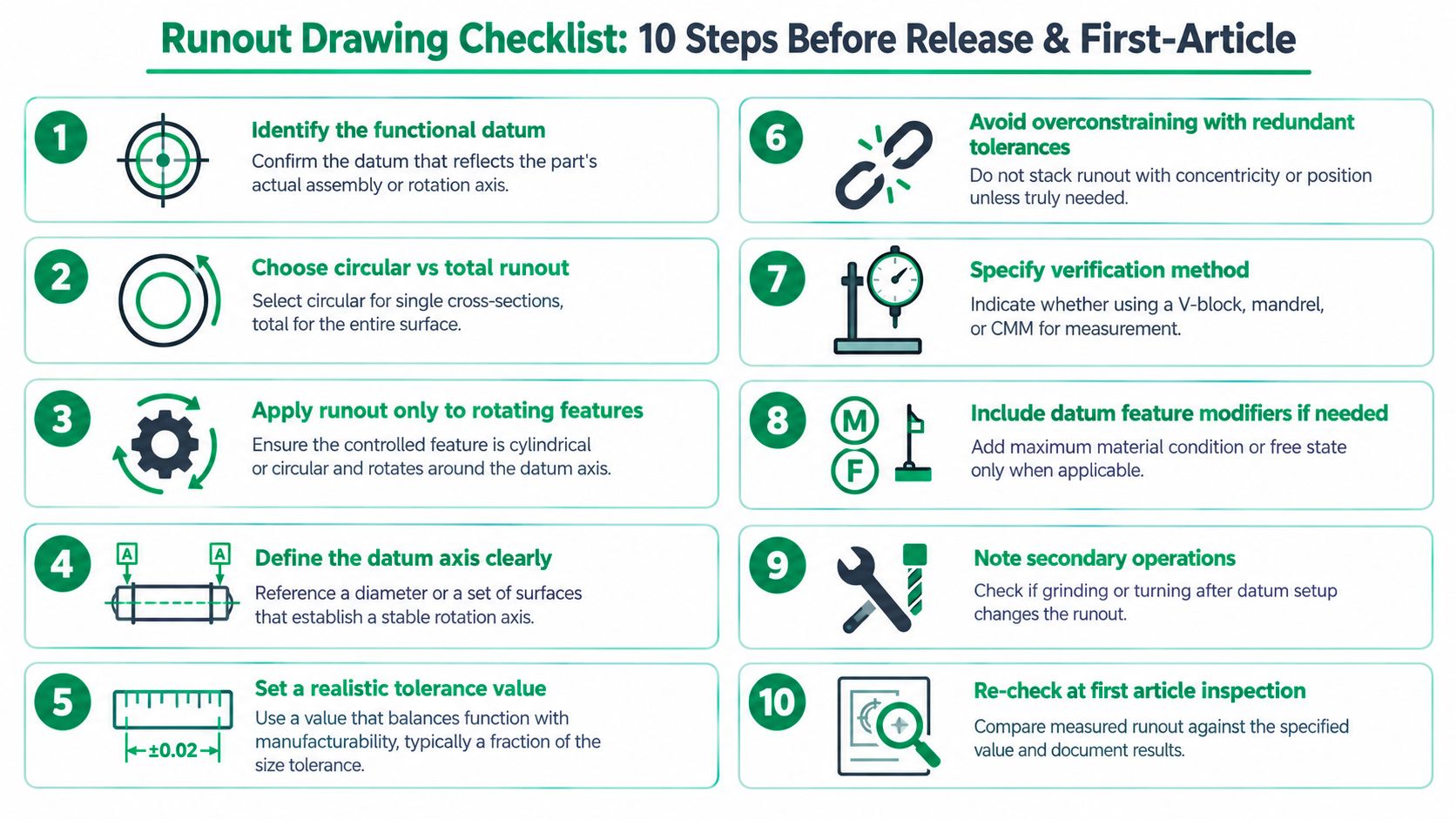
Use this checklist during design release and again at first-article inspection:
- Identify the functional datum. Confirm which surface establishes the actual assembly or rotation axis.
- Choose circular or total runout. Use circular for a single section and total for a complete surface.
- Apply runout to rotating geometry. Keep the control on cylindrical, conical, circular, or comparable rotational features.
- Define the datum axis clearly. Check datum feature size, separation, order, and stability.
- Set a realistic tolerance. Relate the value to the available assembly clearance and manufacturing capability.
- Avoid redundant controls. Don't add runout beside profile, position, or other controls unless each one serves a distinct function.
- Specify the verification method. Identify whether the shop will use centers, a mandrel, a rotary fixture, or a CMM.
- Review applicable modifiers. Use datum feature modifiers only when the design intent and standard permit them.
- Account for secondary operations. Grinding, turning, plating, and reclamping can change the relationship to the datum.
- Recheck at first article. Compare the measured result with the feature control frame and retain the inspection record.
For prototypes and short CNC runs, validate the setup before cutting a batch. Soft jaws can hold a previously machined datum on a turning center, while a quick bench indicator sweep can reveal a bad reclamp before the part goes to the CMM. If you need a machining partner to review the drawing, inspect runout, and produce prototype or low-volume parts, FIRMFG provides CNC turning and milling, CMM inspection, DFM feedback, and related manufacturing support.
Visit FIRMFG with your drawing and functional runout requirement before releasing the job. Their team can help align datum strategy, CNC process planning, and inspection so the specified callout measures the condition your shaft, bore, seal, or rotating assembly needs.