A complete guide to CNC turning machining. Learn how it works, key design tips (DFM), and how to choose the right process for your parts.
You've finished the CAD. The part looks straightforward on screen: a stepped shaft, a few grooves, a bearing seat, maybe a thread on one end. Then the key question lands. Can this be made easily, accurately, and without a string of revisions from your supplier?
That moment is where many designs either stay clean or get expensive fast. A part that seems simple in CAD can turn awkward once tooling, workholding, tolerances, and feature access enter the conversation. For round parts, CNC turning machining is often the right answer, but only if the geometry respects how the process operates.
If you're still deciding between turning, milling, or a mixed process, it helps to start with the broader context of custom CNC machining methods. Turning isn't just “the machine shop way to make round things.” It's a mature production method built around rotational symmetry, repeatability, and efficient material removal for axis-based parts.
A new mechanical designer usually gets tripped up in the same places. They know what shape they want, but not what the tool can reach. They call out tight tolerances on every diameter, even when only one surface matters. They add sharp corners, deep narrow grooves, or thin walls that look harmless in CAD but create chatter, deflection, or extra setups on the machine.
The good news is that turning is one of the most intuitive machining processes once you see it from the machine's point of view. Think less like a CAD user placing features and more like a machinist controlling access, rigidity, and sequence. That shift makes your drawings cleaner, your quotes more predictable, and your finished parts much more likely to match design intent the first time.
Table of Contents
- What the designer usually wants
- What the machine cares about
- How the process actually works
- Core operations you'll see on drawings
- Why turning became a standard industrial process
- What a 2-axis lathe can do well
- Why setup count matters to your design
- When to ask a supplier about machine capability
- Material choice affects more than strength
- Tolerances should follow function
- Surface finish is a geometry issue in disguise
- The most useful drawing habit
- Use radii and reliefs intentionally
- Thin walls and long slender parts need restraint
- A practical DFM checklist for turned parts
- The cheapest improvement is usually on the drawing
- Where CNC turning machining shows up most often
- The practical selection question
- What to check before placing the order
Introduction From Digital Design to Physical Part
A common first part in robotics or instrumentation is a turned shaft with a few functional details: one journal for a bearing, a groove for a retaining ring, a shoulder to locate an encoder hub, and a threaded tip for assembly. In CAD, you revolve a sketch, add a few cuts, and you're done in minutes.
Manufacturing doesn't see that model the way you do. The machine sees a rotating blank, tool approach directions, clamping limits, and a sequence of operations that must happen without losing concentricity. That difference matters. A tiny design choice, like placing a relief groove too close to a shoulder, can decide whether the part runs in one clean setup or requires additional tooling and handling.
What the designer usually wants
Most designers want four things at once:
- Accurate diameters that fit bearings, bushings, or seals
- Clean transitions between steps and grooves
- Reasonable lead time for prototypes and revisions
- Low process risk when parts move from one-off builds to repeat runs
Those goals line up well with turning when the part has a clear central axis.
What the machine cares about
The lathe doesn't care that your CAD is elegant. It cares whether the cutting tool can reach the feature, whether the stock stays rigid while spinning, and whether the tolerance stack makes sense for the actual function of the part.
**Practical rule:** If the part's most important surfaces are concentric around one centerline, turning usually deserves first consideration.
That's why CNC turning machining is so common for spacers, bushings, pins, nozzles, couplings, valve elements, and motor-related shafts. The process naturally creates rotational features with strong consistency because the part spins on its own axis while the tool moves in controlled paths.
A good turned design starts when you ask one simple question before releasing the drawing: Which surfaces need the machine to hold the axis relationship tightly? Once you answer that, the rest of the design gets clearer.
The Fundamentals of CNC Turning
CNC turning can be easily visualized. Think of a potter's wheel. The clay spins, and the shaping tool stays in a controlled position while material changes form. In turning, the principle is similar, except the stock is metal or plastic, the “hands” are cutting tools, and the machine controls the motion with far more force and precision.

How the process actually works
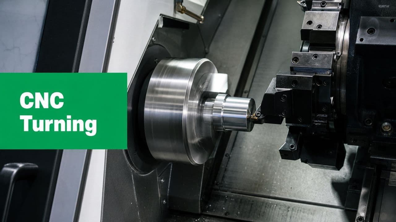
CNC turning is primarily a workpiece-rotation process: the stock is clamped in a spindle or chuck and spun while a stationary cutting tool feeds along linear axes to remove material. That makes it especially efficient for cylindrical, conical, and helical geometries, as described in Xometry Pro's turning overview.
The central machine elements are straightforward:
- Spindle and chuck hold and rotate the raw stock.
- Cutting tool removes material by moving into the spinning workpiece.
- Turret carries multiple tools so the machine can switch from one operation to another.
- Axes usually move the tool along the part length and across the diameter.
When designers hear “lathe,” they often picture only outer diameters. In practice, turning covers much more than that.
Core operations you'll see on drawings
A turned part may include several of these operations in one cycle:
- Facing creates a flat end surface.
- OD turning reduces the outside diameter.
- Boring enlarges or finishes an internal hole.
- Grooving cuts narrow channels.
- Threading forms external or internal threads.
- Parting cuts the finished part off from the bar.
If you're ordering prototypes or bridge volumes, low-volume CNC machining workflows often combine these steps efficiently without the dedicated tooling that mass production may use.
A turned part is usually cheapest when most of its important geometry can be made by feeding a tool in simple, accessible moves along the spinning axis.
Why turning became a standard industrial process
Turning's modern form came out of the broader numerical-control shift that began in 1952, when MIT and the U.S. Air Force demonstrated the first working numerically controlled machine. By 1958, the first CNC machine was patented, and by 1967 the first true CNC milling machine reached the market. By the late 1960s, CNC machines were in extensive use as computer technology caught up with NC operation, according to this CNC machining history summary.
For designers, the historical point is practical, not academic. Turning isn't an exotic method. It's part of a mature manufacturing system developed over decades to produce repeatable parts with less dependence on manual setup skill alone.
From Lathes to Multi-Axis Turning Centers
The phrase “lathe part” can hide a big range of machine capability. A basic 2-axis machine and a modern multi-axis turning center may both produce round parts, but the design freedom they allow is very different.

What a 2-axis lathe can do well
A 2-axis lathe typically moves the tool in two directions:
| Machine motion | What it affects on the part | Typical use |
|---|---|---|
| X-axis | Diameter | Steps, grooves, outer profiles |
| Z-axis | Length | Faces, shoulders, axial positioning |
For straightforward shafts, bushings, spacers, and threaded pins, that's often enough. If every feature is centered on the rotation axis, a simple lathe may be the most efficient choice.
Where new designers get caught is assuming any feature on a round part belongs on a lathe. It doesn't. The moment you add a flat, an off-center hole, or a radial slot, you've left pure 2-axis territory.
What extra axes change
Modern CNC turning centers aren't limited to simple layouts. Industry references note configurations with 3, 4, or even 5 axes, and reported precision can range from about ±0.127 mm in standard production to as tight as ±0.001 mm for precision machining, as described by MachineMetrics on CNC turning center basics.
That matters because additional axes allow the machine to control more than roundness and length. They let it position the spindle and tooling for secondary features without removing the part.
A few practical examples:
- C-axis capability lets the spindle stop at a defined angular position.
- Live tooling adds rotating cutters in the turret, so the machine can drill or mill selected features.
- Additional axis motion helps create more complex relationships between turned and milled details.
If a part is mostly round but includes a few flats or cross-holes, a turning center with live tooling can often hold those relationships better than moving the part to a separate mill.
Why setup count matters to your design
Every time a shop removes and reclamps a part, it introduces a fresh opportunity for positional error. The part may still be good, but the process becomes more sensitive to fixture quality, operator method, and datum transfer.
That's why multi-axis turning centers are such a practical bridge between CAD intent and production reality. A designer can place a groove, thread, face, and radial hole on one model. The shop can often produce those features in one machine cycle rather than splitting the work across machines.
When to ask a supplier about machine capability
Ask early if your part includes any of these features:
- Off-axis holes in a cylindrical body
- Flats for wrenching or orientation
- Slots or milled pockets on an otherwise round part
- Features on both ends that need strong coaxial control
Those aren't red flags. They're signs that machine selection matters. The same nominal geometry can be easy on one turning center and awkward on another.
Materials Tolerances and Surface Finishes
A turned part isn't defined by geometry alone. Three decisions shape the result just as much: material, tolerance, and surface finish. Designers often separate them on the drawing, but the machine experiences them together.
A stainless shaft, for example, may hold a diameter just fine but require more care to achieve a smooth finish at a shoulder transition. A plastic bushing may machine quickly but deform if wall sections get too light. The point isn't that one material is “better.” It's that each material changes how aggressive the process can be and how stable the part remains during machining.
Material choice affects more than strength
In turned parts, the material influences chip formation, heat, tool wear, burr behavior, and part stiffness during clamping.
Designers commonly specify materials such as aluminum, stainless steel, brass, or engineering plastics for turned components. The right choice usually comes from function first, but manufacturability should follow closely behind. If two materials satisfy the design, the easier-machining option may reduce process risk and simplify inspection, especially for prototype work.
Tolerances should follow function
Not every diameter deserves the same limit.
If a shaft has one bearing seat, one clearance region, and one cosmetic section, the tightest tolerance usually belongs on the bearing seat. Calling out the whole part tightly adds cost without improving performance. It also makes quoting harder because the supplier must treat every surface as critical, even when it isn't.
For parts with demanding fits, it helps to align your expectations with realistic process capability. If you know a feature needs very tight control, call it out specifically and avoid spreading that requirement across unrelated surfaces. For additional context on that trade-off, tight-tolerance machining guidance is useful when preparing drawings and RFQs.
Tight tolerances are easiest to justify when you can point to a fit, seal, bearing, or alignment function. If you can't name the function, the tolerance may be stricter than needed.
Surface finish is a geometry issue in disguise
Designers sometimes treat finish as a cosmetic afterthought. In turning, finish is closely tied to tool shape, feed, material response, and part rigidity.
A finish callout on a bearing land or sealing surface tells the machinist something functional. It says friction, wear, or leakage matters there. A finish callout on a hidden spacer face may do nothing but increase cycle time.
Here's a practical way to view this:
| Requirement | Typical design meaning | Machining implication |
|---|---|---|
| Smooth bearing or sealing surface | Contact performance matters | Tooling and cut conditions may need more control |
| General machined surface | Function is less sensitive | Standard turning passes may be enough |
| Cosmetic visible area | Appearance matters | Extra finishing attention may be needed |
The most useful drawing habit
Flag only the surfaces that matter. Pair those notes with a clear datum strategy and a sensible tolerance stack. That gives the shop room to machine the rest of the part efficiently while protecting the features your assembly depends on.
Designing for Manufacturability in Turning
Many otherwise solid CAD models run into trouble. The design may be functional, but the feature choices force unstable cuts, specialized tools, or unnecessary setups. Good DFM in turning doesn't mean making the part crude. It means shaping the geometry so the machine can reach it cleanly and hold it consistently.

Start with feature access
The first DFM question for a turned part is simple: Can a standard turning tool physically reach the feature?
That's where undercuts and sharp transitions become important. Undercut features sit behind walls or shoulders where standard tools cannot reach directly, and sharp-corner handling often requires tool-radius compensation, multiple passes, or specialized tooling, forcing extra setups or nonstandard tooling, as discussed in this undercut machining reference.
If you place a groove directly behind a tall shoulder, the CAD may look neat while the actual tool path becomes awkward. The supplier may still make it, but the process could require narrower tools, more careful programming, or a second operation.
Use radii and reliefs intentionally
Internal sharp corners are a common mismatch between CAD and machining reality. Cutting tools have geometry. They don't create infinitely sharp internal corners by default.
A better habit is to add relief where a mating part doesn't need a perfect corner. That gives the tool room to exit and helps the shoulder clean up properly. It also makes inspection easier because the functional surfaces become clearer.
Consider these design choices:
- Add corner reliefs where two diameters meet but only one is functionally critical.
- Avoid decorative sharp transitions that don't serve assembly or fit.
- Size grooves realistically so standard tooling can enter and exit without rubbing.
A shoulder that looks crisp in CAD may be harder to machine than a slightly relieved feature that performs the same job in the assembly.
Thin walls and long slender parts need restraint
Designers often focus on final geometry and forget the part must survive the cut while spinning. Thin walls can distort under clamping or cutting pressure. Long, narrow shafts can deflect and vibrate.
Turning guidance often notes a trade-off that beginner content skips: a positive rake and smaller nose radius can help surface finish, but geometry that helps finish can also reduce stability in some situations. Guidance also notes that large approach angles around 90° reduce passive force, while smaller approach angles can increase vibration and bending on long, thin workpieces, as described in this turning geometry discussion.
That matters in real design work. If you specify a slender stem, deep profile, or thin flange, don't assume the shop can “take lighter cuts” and solve everything. The geometry itself may push the process toward chatter or deflection.
A practical DFM checklist for turned parts
Use this before sending a drawing out:
- Check rotational logic
Ask whether the majority of critical features share one centerline. If not, the part may need a mixed turning and milling strategy.
- Review shoulder accessibility
Look at every groove, thread runout, and step. Can a tool enter, cut, and exit without colliding with the adjacent wall?
- Soften nonfunctional corners
If a sharp internal corner isn't sealing, locating, or mating, add a radius or relief.
- Control wall behavior
Keep thin sections to the minimum your function requires. A visually elegant thin ring can become a distortion problem in production.
- Limit tolerance spread
Put tight controls on the surfaces that matter, not on every turned diameter.
The cheapest improvement is usually on the drawing
Most turned-part cost increases don't begin at the machine. They begin when the drawing implicitly demands awkward tool access, broad tight tolerances, or features that need special handling. A small change in radius, groove position, or wall thickness often removes the problem before the quote ever arrives.
Turning vs Milling and Common Applications
The simplest rule is still the most useful: round parts turn, blocky parts mill. If the main shape is built around a center axis, turning is usually the first process to consider. If the part is mostly flat-sided or needs multiple unrelated faces, milling usually takes over.

That rule works because the motion is different. In turning, the workpiece rotates. In milling, the tool rotates while moving around a more fixed workpiece. So the part's dominant geometry should guide the process choice, not the fact that both machines are “CNC.”
A quick decision framework
| Part characteristic | Turning fits better | Milling fits better |
|---|---|---|
| Mostly cylindrical | Yes | Sometimes only for secondary features |
| Mostly prismatic or flat-sided | Rarely | Yes |
| Strong concentricity needs | Yes | Usually secondary choice |
| Multiple side faces and pockets | Limited unless live tooling helps | Yes |
A part can sit in the middle. A mostly round component with flats, cross-holes, or slots may still start on a turning center if those secondary features are limited and the machine has the right capability.
Here's a useful visual explanation of the comparison:
Where CNC turning machining shows up most often
Turning is common in products that rely on rotational parts and repeatable fits:
- Robotics uses shafts, standoffs, collars, and couplings.
- Medical and fluid systems use nozzles, connectors, and valve-related components.
- Aerospace and industrial equipment use fasteners, fittings, pins, and precision cylindrical interfaces.
Historically, CNC machining was already moving from specialized use toward broad industrial adoption by the late 1980s and 1990s, and Xometry notes that by 1989 CNC machining had become the standard for large-volume manufacturing and production. That same history also points to early CNC-related work in 1949, adoption acceleration in the early 1980s as microcomputers became more affordable, and expansion into industries beyond aerospace, as summarized in Xometry's CNC machining history.
The practical selection question
When you're deciding between turning and milling, don't ask which machine is more advanced. Ask which one matches the part's natural geometry with the fewest awkward operations. The process that respects the shape usually gives you the cleaner quote, simpler inspection plan, and lower manufacturing risk.
Partnering with a CNC Supplier Like LC Proto
A turned part can look perfect in CAD and still become expensive, slow to inspect, or hard to hold in production once it reaches the shop. That gap usually shows up in small details. A groove that is easy to sketch may force a special tool. A long, thin stem may deflect during cutting. A tight tolerance on a nonfunctional diameter can drive cost without improving the part.
That is why supplier selection matters early, while the drawing can still change.
For prototype and low-volume work, the best shop conversations happen before chips are cut. A useful supplier reviews the part the way an experienced designer would review an assembly. They ask what surface locates the part, which diameter carries the fit, and which features are cosmetic versus functional. Those questions help connect CAD intent to a process plan that can be machined and inspected with less risk.
What to check before placing the order
A capable supplier should answer a few practical questions in plain language:
- DFM feedback
Will they point out tool access problems, thin unsupported sections, awkward undercuts, or tolerance callouts that do not match the part's function?
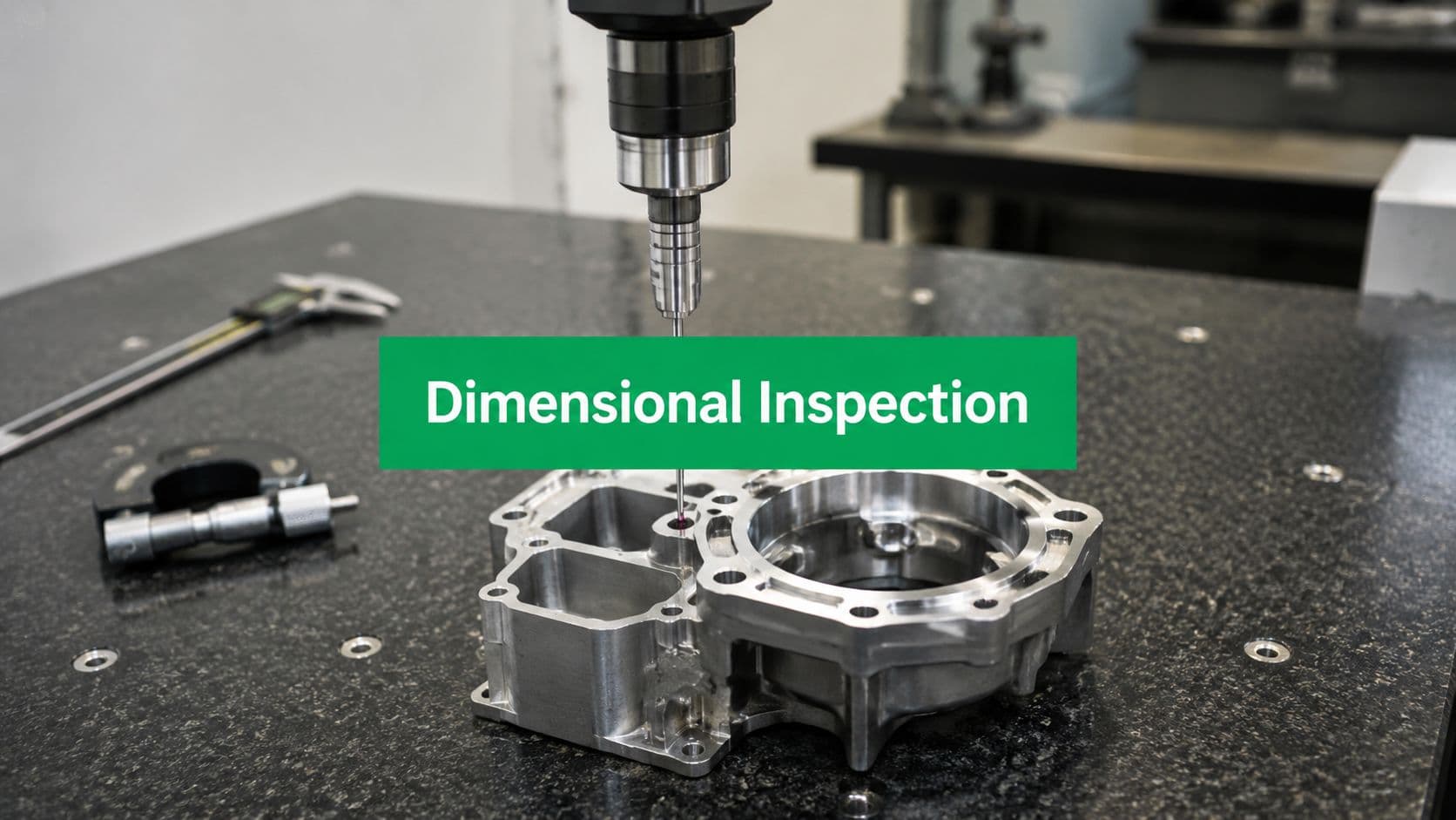
- Inspection method
How will they check the features that matter most, such as critical diameters, concentricity-sensitive surfaces, shoulder locations, or runout-related relationships?
- Material and finishing scope
Can they machine the alloy or plastic you specified, and can they support any coating, anodizing, passivation, or other finish the application requires?
- Communication quality
Do they ask about fit, load path, sealing surfaces, and datums, or do they only send back a quote?
A strong manufacturing partner does more than follow the print. They review whether the part can be cut in one setup or needs multiple operations. They look for dimensions that stack unnecessarily. They check whether the datum scheme gives inspection a clear starting point. For a new mechanical designer, that feedback is useful because it shows which dimensions control function and which ones only make the drawing harder to build.
LC Proto, for example, offers CNC turning as part of its machining services and uses a DFM-first workflow with in-process quality control and final inspection. That kind of process is helpful when a prototype has little tolerance for misunderstanding, especially if the design mixes precision diameters, threads, and surface finish requirements on the same part.
The most useful supplier is usually the one that raises the awkward question before machining starts. If one small feature makes the whole part harder to produce, they should say so clearly. A slightly wider relief, a different groove position, or a cleaner thread runout callout can keep the design intent intact while making the part easier to machine repeatably and easier to inspect with confidence.