Learn the core principles of Design for Manufacturability (DFM). Our guide covers process-specific rules, tolerancing, and how to avoid costly errors.
You finish the CAD. The model looks clean, the surfaces are resolved, the assembly fits, and the prototype review felt solid. Then the quote comes back. The cost is far above target, the lead time is longer than the project can absorb, and the manufacturer has flagged a list of issues no one discussed during design.
That moment is where many teams first meet design for manufacturability in a serious way.
Good DFM isn't a checklist you run at the end. It's a way to control risk while the design is still flexible. It connects design intent to process capability, inspection reality, supplier constraints, and assembly behavior. Done early, it prevents the kind of changes that force rework, schedule slip, and expensive compromise later.
Table of Contents
- DFM is risk management, not rule policing
- Complexity is a cost decision
- The strongest DFM moves happen early
- Tight tolerances change everything
- Assembly stack-up is where teams get surprised
- Start with the part's real requirement
- A practical process selection frame
- What a strong design package includes
- Good DFM feedback is not criticism
- First pass checks before you request a quote
- Process and drawing checks before release
From Perfect CAD to a Painful Quote Why DFM Matters
A product team can spend weeks refining a part and still miss the features that drive machining time, fixture complexity, mold difficulty, or inspection burden. The CAD may be perfect from a design standpoint and still be a poor manufacturing package. That gap is why DFM matters.
A common example is a housing that looks straightforward on screen but includes deep pockets, hard-to-reach internal corners, cosmetic surfaces on every face, and tight tolerances applied to nearly every dimension. Nothing is obviously wrong in isolation. In production, everything is wrong together. The shop now needs more setups, smaller tools, slower feeds, more inspection time, and possibly a different process plan than the one the designer assumed.
**Practical rule:** If a supplier has to “figure out how to make it” after the design is complete, the design is already carrying avoidable risk.
This is not just a quoting issue. It is a timing issue. aPriori's DFM guidance notes that concept-phase DFM decisions can swing manufacturing lead times by 25% to 1,480% and costs by 15% to 800% when challenging features are introduced. The same guidance says effective DFM can reduce manufacturing costs by 15% to 40% and cut lead times by 25% to 60% versus non-optimized designs.
Why late fixes hurt so much
Once the team has released drawings, ordered tooling, locked interfaces, or committed to test hardware, redesign gets expensive fast. A small geometry change may force a fixture change, a toolpath rewrite, new inspection programming, or an assembly update. If molding is involved, the consequences are worse because tooling has already started to define the economics of the part.
DFM works because it moves those decisions upstream. It asks simple but high-value questions early:
- Can this feature be made with standard tooling
- Does this tolerance support function, or just preference
- Is this geometry aligned with the chosen process
- Can the part be inspected without custom workarounds
DFM is risk management, not rule policing
The best teams use DFM to expose trade-offs before they become problems. They don't treat it as a set of shop-floor objections. They treat it as a design review discipline that protects cost, time, and quality together.
A good DFM review should tell you where your design is fragile. It should show which features are safe, which are expensive, and which are likely to create instability between prototype and production.
The Core Principles of Design for Manufacturability
Design for manufacturability starts with one idea: make the product easy to build on purpose. That sounds obvious, but many designs still evolve the opposite way. Teams optimize for appearance, packaging, or isolated performance targets, then try to force the finished geometry through a process that was never considered seriously enough.
The easiest mental model is simple building blocks. Standard parts, repeatable geometry, accessible features, and common materials behave like standard LEGO bricks. They assemble predictably, they work across more situations, and they reduce surprises. Custom geometry everywhere behaves like a box of one-off pieces. It may still work, but every decision gets slower and more expensive.

Complexity is a cost decision
The fastest DFM wins usually come from simplifying the design before anyone starts optimizing single features. One industry guide states that DFM can lower total costs by up to 50% when applied effectively, largely by minimizing complexity through practices like part reduction and standard components. Those same practices also improve assembly speed and quality.
That principle shows up in a few reliable ways:
- Reduce part count: Every extra part adds handling, alignment, tolerance interaction, and assembly risk.
- Standardize where possible: Common fasteners, standard stock sizes, familiar materials, and repeated feature sizes shorten setup and reduce purchasing friction.
- Match geometry to process: A shape that is easy for CNC may be awkward for molding. A molded part may be inefficient as a machined prototype unless you redesign it for machining.
- Remove nonfunctional difficulty: Decorative contours, unnecessary pockets, and hard-to-reach features often add cost without improving performance.
A part can meet every functional requirement and still be overdesigned for manufacturing.
The strongest DFM moves happen early
The first DFM pass shouldn't begin with fillets, corner breaks, or drawing cleanup. It should begin with architecture. Ask whether the product needs this many parts, this many custom interfaces, and this much variation in hardware and materials.
A practical first-pass screen looks like this:
| Question | What to look for |
|---|---|
| Can parts be combined | Brackets, covers, spacers, and cosmetic pieces that don't need to remain separate |
| Can features be repeated | Same hole sizes, same corner radii, same thread forms, same wall strategy |
| Can materials be simplified | Fewer grades, easier sourcing, process-compatible choices |
| Can the process be made obvious | Geometry that naturally fits machining, molding, bending, or printing |
Good DFM doesn't ask the design team to lower standards. It asks the team to stop paying for difficulty that adds no functional value.
Process-Specific DFM Rules You Must Know
General DFM principles are useful, but quoting problems usually come from process-level mistakes. A part is hard to machine, hard to mold, awkward to bend, or unstable to print. Once you know which process is carrying the job, the design rules get more concrete.
CNC machining
CNC punishes inaccessible geometry. Designers often create internal features that look minor in CAD but require long tools, special fixturing, or extra setups in reality. Internal corners are the classic example. Rotating tools leave radii, so sharp inside corners force secondary operations or redesign.
Use these checks first:
- Give internal corners realistic radii: Larger internal radii let the shop use larger cutters, which usually means better stability and less cycle time.
- Design for tool access: Deep, narrow pockets and tall thin walls create chatter risk, tool deflection, and slower machining.
- Align features when possible: Features that work from standard directions are easier than compound-angle geometry that pushes the part into more complex machining.
- Limit unnecessary setups: Features on multiple faces may be fine. Features on many odd orientations often drive time more than designers expect.
If your team wants a refresher on subtractive process constraints, this overview of CNC machining fundamentals is a useful reference.
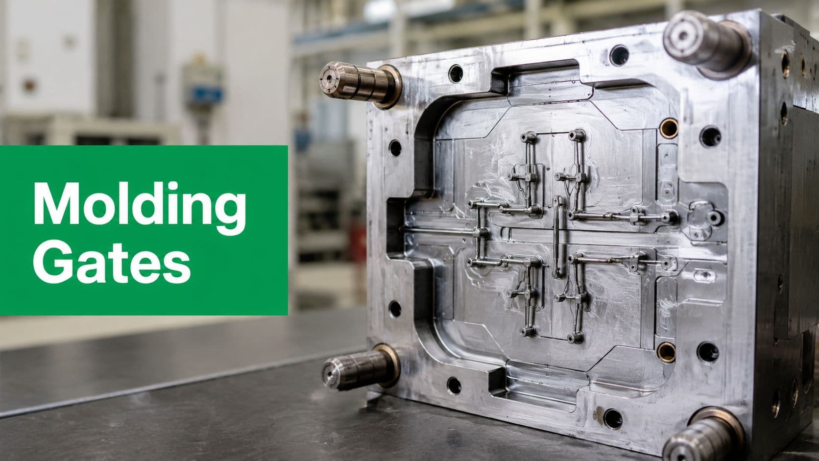
Injection molding
Molding rewards consistency and punishes hidden complexity. Many prototype teams underestimate how strongly wall strategy, draft, and undercuts affect mold design and part quality. A molded part that looks elegant can still be troublesome if the walls vary too much or if the ejection path isn't clean.
Pay attention to these rules:
- Use consistent wall thickness where possible: Sudden thick-to-thin transitions can create cosmetic and dimensional issues.
- Add draft intentionally: Vertical faces need release strategy. If a surface must stay visually straight, make that decision knowingly and discuss the tooling consequence.
- Avoid undercuts unless they earn their keep: Side actions and complicated tooling are sometimes necessary, but they should solve a real requirement.
- Place details where the tool can support them: Small text, snaps, bosses, and shutoff features need enough strength to mold cleanly and repeatably.
Sheet metal fabrication
Sheet metal looks simple because the starting material is simple. The manufacturing reality is less forgiving. Bend sequence, tool access, grain direction, flat pattern logic, and hardware insertion all affect whether the part can be made without workarounds.
The common misses are usually these:
- Keep bend strategy realistic: Tight offsets, crowded bends, and trapped tool access can force redesign.
- Respect hole-to-bend relationships: Features too close to bends often distort or create tolerance trouble.
- Standardize thickness and hardware: Mixing thicknesses and unusual insert schemes makes low-volume work more cumbersome than it needs to be.
- Think in flat pattern first: If the part can't be unfolded logically, the design likely needs revision before release.
3D printing
Additive manufacturing gives designers more geometric freedom, but it doesn't eliminate DFM. It just changes the rules. Overhangs, support removal, orientation, trapped powder or resin, and post-processing all become part of the design problem.
Use additive carefully:
- Choose orientation early: Surface quality, support marks, and dimensional behavior all depend on orientation.
- Avoid enclosed features you can't clean: Internal channels and cavities need a plan for material removal and verification.
- Design for post-processing: Threads, sealing faces, and bearing fits often need secondary machining or finishing.
- Know when printing is the wrong answer: A printable shape isn't automatically the best production path.
Here is a simple comparison teams can use during design review.
DFM Considerations by Manufacturing Process
| Constraint | CNC Machining | Injection Molding | Sheet Metal | 3D Printing |
|---|---|---|---|---|
| Internal corners | Need radii for tool clearance | Usually not the main issue | Not applicable in the same way | Geometry is freer, but cleanup matters |
| Wall strategy | Thin walls can chatter | Consistency matters for molding behavior | Thickness tied to stock | Thin features may be fragile or warp |
| Access | Tool reach drives cost | Tooling split and ejection drive decisions | Brake and punch access matter | Support access and removal matter |
| Complexity penalty | More setups and longer cycle time | More complicated tooling | More difficult forming sequence | More post-processing and print risk |
| Best design habit | Keep features open and reachable | Design for draft and release | Think through bends first | Design around orientation and finishing |
The pattern across all four processes is simple. DFM works when the designer stops thinking of shape as abstract geometry and starts thinking of it as something a specific process has to create, hold, and verify.
Mastering Tolerances The DFM Balancing Act
Most cost problems hidden in drawings come from tolerances, not from the nominal geometry. Teams often debate material, process, and finish in detail while leaving default tolerances untouched across the print. That is where parts become expensive without anyone meaning to make them expensive.
A practical DFM guide from Five Flute makes the point clearly: looser tolerances can reduce part cost by increasing production speed, extending tool life, simplifying quality control, and lowering scrap, while overly tight tolerances are a common preventable cost driver.
Tight tolerances change everything
A tight tolerance doesn't just affect one dimension. It changes how the shop machines the feature, how often it measures the feature, how it fixtures the part, and how much process variation it can tolerate before scrap becomes likely.
That is why strong drawings separate critical-to-function features from everything else. If a bore controls alignment, seal compression, bearing fit, or a press-fit condition, tighten it. If a cover edge, outer profile, or clearance surface doesn't change function, relax it.
Use this filter before releasing a drawing:
- Function first: Does the tolerance control fit, motion, sealing, or load path?
- Assembly second: Does variation here affect stack-up or interface location?
- Inspection reality: Can the feature be measured directly and repeatably?
- Cost consequence: Are you willing to pay for the process control this callout requires?
For teams refining annotation strategy, this guide to geometric dimensioning and tolerancing is worth reviewing before final release.
If every dimension is tight, none of the dimensions are prioritized. The shop is forced to treat the whole part as critical.
Assembly stack-up is where teams get surprised
Single-part tolerances can look harmless. Assemblies expose the problem. A bracket, a spacer, a housing, and a cover can all be “in tolerance” individually and still create misalignment, preload issues, or cosmetic mismatch when assembled together.
That is why tolerance decisions should be made at system level, not feature by feature. Reserve the tightest limits for the interfaces that set function. Then open the rest enough that the process remains stable and inspection stays practical.
A useful habit is to mark drawings in two layers:
| Drawing layer | What belongs there |
|---|---|
| Critical controls | Mating features, datums, sealing faces, locating patterns |
| General controls | Non-critical profiles, cosmetic edges, clearance features |
That split keeps the drawing honest. It tells the manufacturer where precision matters and where flexibility is acceptable. In practice, that often prevents more delay than any single geometry change.
Choosing the Right Process An Advanced DFM Strategy
A lot of DFM advice starts too late. It assumes the process has already been chosen, then focuses on making the design friendlier to that decision. That works sometimes. It also traps teams into optimizing the wrong path.
One of the most valuable DFM questions is not “How do we make this CNC-friendly?” It is “Should this part be CNC machined at all?” Modus Advanced argues this gap directly, noting that a key DFM decision is choosing the most manufacturable process under current cost, quality, and scalability constraints, not merely optimizing for one process.

Start with the part's real requirement
Many teams choose a process for the wrong reason. They choose CNC because it feels precise, molding because the part is plastic, or additive because the geometry is complex. Those can all be reasonable instincts. They are not enough by themselves.
The better starting questions are:
- What must the part do
- What volume is realistic
- Which surfaces and features are critical
- What lead time can the project absorb
- Will the design need rapid iteration or stable repeat production
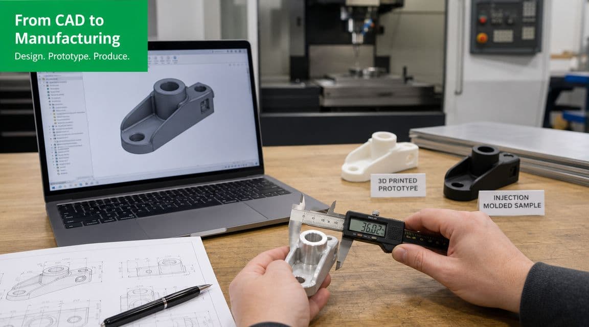
A prototype housing with frequent design revisions may be best machined even if the production version will be molded. A geometry-heavy metal part with hard-to-reach internals may need additive plus secondary machining instead of forcing everything through 5-axis cutting. A simple bracket may not need a premium process at all.
A practical process selection frame
Use this review structure during concept work:
| Design condition | Process question |
|---|---|
| Complex internal geometry | Would additive reduce feature difficulty enough to justify finishing steps |
| Tight cosmetic plastic surfaces | Should the team prototype for appearance separately from production tooling strategy |
| Flat parts with bends and cutouts | Can sheet metal replace a heavier multi-part machined assembly |
| High iteration expected | Which process tolerates design changes with the least disruption |
The most manufacturable design is not always the one with the cleanest CAD model. It is the one matched to the process that can produce it reliably without heroics.
DFM transforms into a real engineering discipline. It stops being a compliance exercise and becomes a decision framework for risk, speed, and scale.
From Design to Delivery Collaborating with Your Manufacturer
DFM is a conversation between the design team and the people who will build, inspect, and sometimes assemble the part. When that conversation starts late, everyone works from assumptions. Designers assume capability. Manufacturers assume intent. Quotes get padded, questions multiply, and avoidable revisions show up at the worst time.
The teams that move faster usually submit better information, not just better geometry.
What a strong design package includes
A good package gives the manufacturer enough context to make smart choices without guessing. That means more than uploading a STEP file and waiting for feedback.
Include these items:
- Clear critical features: Mark what controls fit, function, sealing, alignment, or appearance.
- Useful drawing notes: Call out surface finish, datum scheme, material condition, and any absolute requirements.
- A realistic model state: Suppress ideas that won't be built. Prototype CAD should match prototype intent.
- Assembly context when needed: If one part's dimensions only make sense relative to another part, share that relationship.
If the build includes qualification or controlled handoff, align the drawing package with the inspection plan early. Teams often wait too long to define what must be verified on first build. This overview of first article inspection helps frame that discussion.
Good DFM feedback is not criticism
The best designers invite pushback. If a manufacturer suggests changing a fillet, widening a slot, relaxing a non-critical tolerance, or splitting a geometry into a different process path, that is not a sign the design failed. It means someone is doing the expensive thinking before material is cut.
A useful review meeting usually focuses on four things:
- What is functionally fixed
- What is preferred but negotiable
- What is expensive or unstable to manufacture
- What can be changed now with the least downstream impact
A manufacturer becomes valuable when they explain the consequence of a design choice, not just when they point out that it is hard to make.
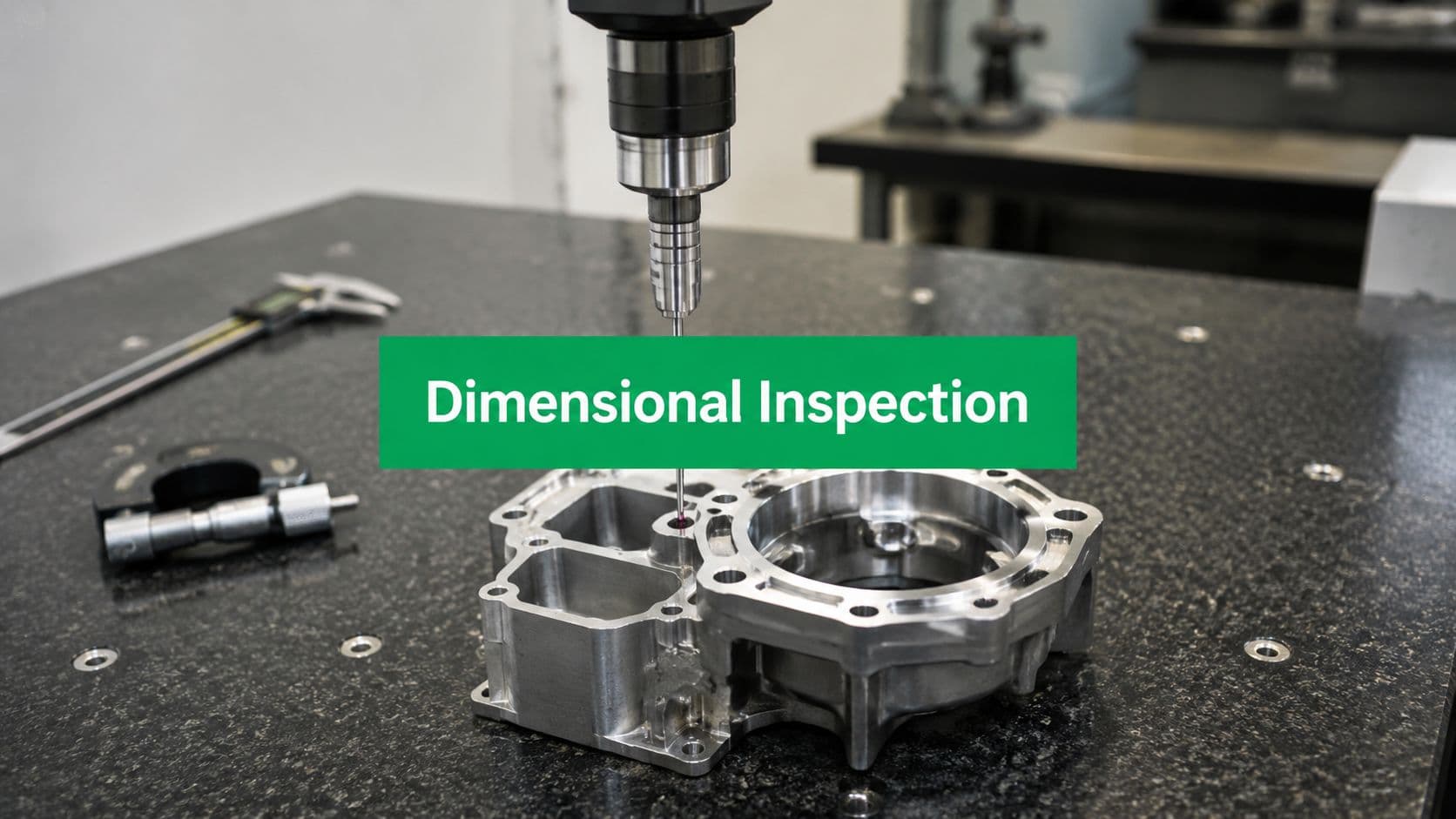
Design for inspectability belongs in the same conversation. If a feature is critical, it should also be measurable with a realistic method. Hidden surfaces, inaccessible datums, and ambiguous profile controls create confusion long after the quote stage.
Your DFM Checklist for Preventing Common Mistakes
Most DFM failures are not exotic. They are ordinary issues that nobody forced into the open soon enough. The design carried too many parts. The wrong process got assumed. Tolerances were copied broadly. Critical features were never clearly distinguished from preferences.
DFMA guidance recommends applying minimum-part-count criteria first, and states that this step can eliminate or consolidate roughly two-thirds of original parts. That is why the first item on any serious DFM checklist should be simplification before detailed optimization.

First pass checks before you request a quote
Run these before you send anything out:
- Part count review: Can any bracket, cover, spacer, or adapter be combined or eliminated?
- Function audit: Does each feature serve fit, strength, sealing, alignment, service, or safety? If not, question it.
- Standardization check: Are hardware, materials, radii, threads, and hole sizes as consistent as they can be?
- Process sanity check: Is the selected process obvious from the geometry, or is the team forcing a mismatch?
This short video is a useful companion when you want a quick visual review of DFM thinking in practice.
Process and drawing checks before release
Use a second pass right before quotation or release:
| Review area | Final question |
|---|---|
| CNC features | Are pockets, corners, wall thicknesses, and access paths realistic |
| Molded geometry | Do draft, wall strategy, and shutoff assumptions make tooling sense |
| Sheet metal | Does bend sequence work without trapped tooling or distorted features |
| Printed parts | Is orientation, support removal, and finishing strategy defined |
| Tolerances | Are tight limits reserved only for true functional interfaces |
| Inspection | Can every critical feature be measured clearly and repeatably |
Then do one more discipline-specific review with the team:
- Mechanical design: Confirm interfaces and stack-up logic.
- Manufacturing engineering: Challenge setups, tooling assumptions, and process choice.
- Quality: Verify datums, measurable features, and realistic acceptance criteria.
- Procurement or supply chain: Check whether materials and standard components are sensible and available.
A strong design for manufacturability review should leave very few open questions. The manufacturer should know what matters, what can move, what process fits best, and what level of control the part requires.
If that isn't clear yet, the design is not ready.