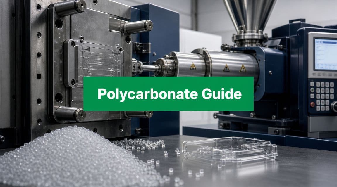
A deep dive into injection molding polycarbonate. Learn PC properties, process parameters, mold design, and troubleshooting for tight-tolerance parts.
You have a part on your screen that leaves almost no room for compromise. It has to stay clear, survive impact, hold alignment with a mating assembly, and keep doing that after heat exposure that would push many plastics out of shape. You check the material shortlist, and the answer keeps coming back to polycarbonate.
That's usually the point where the design conversation gets tense. The material solves the product problem, but it creates a manufacturing one. Injection molding polycarbonate isn't difficult because it's exotic. It's difficult because the process punishes casual decisions. A gate that would be acceptable in ABS can shear PC too hard. A mold temperature chosen to save cycle time can lock in stress that shows up later as warpage, drift, or cracking around a screw boss.
Polycarbonate has been a production material for a long time. Its modern commercial path is commonly traced to 1953–1958, after independent development in the mid-1950s, when Bayer and General Electric brought it into industrial use, as noted in 3ERP's history and process overview of polycarbonate molding. The reason that history still matters is practical: once industry recognized that PC could deliver transparency, toughness, and heat resistance at production scale, molding it became less about novelty and more about disciplined control.
If you're designing a tight-tolerance part, that discipline matters more than the resin name on the print. The useful question isn't “Can this be molded in PC?” It's “Can the tool, process, and geometry work together without baking in stress?”
Table of Contents
- The property mix that changes the material decision
- Where designers usually stop too early
- The published window is only the starting point
- Key Processing Parameters for Polycarbonate
- What each parameter is really doing
- Packing is where dimensions are won or lost
- Dry resin and consistent residence time matter
- Gate choice controls more than fill
- Runner and vent design decide whether the process stays stable
- Low shrink does not guarantee a stable part
- Design moves that help parts stay where you put them
- A better troubleshooting sequence for PC
- Most finish quality is decided before the part is ejected
- Post-processing without creating new problems
Introduction The Polycarbonate Challenge
Designers usually arrive at polycarbonate after other options have already failed the brief. Acrylic may give clarity but not enough toughness. ABS may mold more easily but can miss the thermal requirement. A blend might help processability, but if the part needs the specific balance of impact resistance, dimensional stability, and heat performance that PC is known for, compromises start showing up quickly.
That's why injection molding polycarbonate deserves to be treated as a design-and-process discipline, not just a resin selection. The part quality you get is tightly connected to three things working together: geometry, mold layout, and thermal control. If one of those is off, the others spend the whole program compensating.
A mechanical designer often sees the first warning signs before the molder does. A lens cover that rocks on inspection points. A housing that passes incoming checks but cracks after assembly. A bezel that looks clean at ejection and drifts after sitting under load. None of those failures starts at final inspection. They start much earlier, usually in the combination of restrictive flow, uneven cooling, or a process tuned too hard for speed.
Good polycarbonate parts rarely come from heroic process adjustments. They come from a part and tool that don't force the process into a corner.
The useful mindset is simple. Don't ask PC to behave like a commodity resin. Let the material tell you what the mold and process need. When you do that, you can get clear, tough, dimensionally stable parts that hold tolerance without constant firefighting.
Why and When to Choose Polycarbonate
Polycarbonate earns its place when the part has to do several hard things at once. Not one hard thing. Several.
The property mix that changes the material decision
Design teams keep returning to PC because it sits in a useful middle ground. It offers impact resistance, clarity, heat resistance, and dimensional stability in one material family. That combination is why it remains one of the most widely used plastics when a part can't afford to be fragile, opaque, or thermally sloppy.

One of the better reasons to choose PC is thermal performance under dimensional demand. Protolabs reports that PC's heat-performance benchmark is around 153 °C by dynamic mechanical methods, and that this sits only a few degrees above its Vicat softening point and 10–20 °C above DTUL depending on test geometry and method, as detailed in Protolabs' thermoplastic material selection guide. For designers, that matters because the part isn't just surviving heat. It's doing so while trying to keep fit, flatness, and alignment.
Injection molding also fits the material's production role. It can produce millions of components per year with limited human intervention, and PC is valued in that context for low shrink, good dimensional stability, and strong cosmetic potential, according to the same Protolabs guide. That makes it a realistic production choice, not just a premium prototype material.
Where designers usually stop too early
Teams often choose PC for the obvious reasons and overlook the chief one. The chief reason is risk reduction in service.
Use PC when the part must meet several of these conditions at the same time:
- Stay optically usable: Covers, lenses, guards, and light-guiding components need more than transparency. They need process control that preserves appearance after molding and assembly.
- Take impact without becoming bulky: Protective enclosures and housings often need toughness without shifting to a much thicker wall.
- Hold shape near heat sources: Electronics and medical products may sit close to warm internals or sterilization-related environments where a softer resin starts drifting.
- Keep mating features aligned: Snap details, sealing lands, screw interfaces, and sensor windows usually care more about repeatability than headline strength.
When the program is still early, it's also worth checking whether full molding is the right route yet. For early-stage learning, the trade-offs between low-volume additive work and production tooling can change the schedule more than the material itself. A practical comparison is this overview of injection molding vs 3D printing.
**Practical rule:** Choose polycarbonate when failure in the field would come from a combination of impact, temperature, and dimensional drift. If only one of those matters, a simpler resin may be easier to live with.
Mastering Polycarbonate Processing Parameters
Polycarbonate usually looks forgiving during the first trial. The cavity fills, the part ejects, and dimensions may even look acceptable at room temperature. Then the problems show up later. A lens crazes after assembly, a snap feature whitens, or a flat cover pulls out of tolerance after 24 hours because the process stored too much stress in the part.
That pattern is common with PC because the main settings are tightly linked. Melt temperature affects viscosity, but it also changes how much pressure is needed to fill and pack. Mold temperature affects surface replication, but it also changes stress relaxation, shrink behavior, and cycle time. Fill speed, gate size, and hold pressure have the same kind of coupling. Tight-tolerance PC parts come from balancing that whole system, not from pushing one setting to an extreme.
The published window is only the starting point
Typical PC processing ranges are familiar. Barrel temperatures often run around 260 to 320 °C. Mold temperatures commonly sit around 80 to 120 °C. Injection pressure is often high relative to easier-flowing resins.
Those numbers are useful, but they do not tell you where your stable process will land. A thick, ribbed housing with a direct gate can run well at settings that would leave a thin optical cover short, stressed, or both. In practice, the right window is defined by part geometry, gate restriction, venting quality, and how much dimensional movement the design can tolerate after molding.
If you need a broader review of machine stages and terminology while checking a supplier process sheet, this injection molding process guide is a useful reference.
Key Processing Parameters for Polycarbonate
| Parameter | Recommended Range | Notes |
|---|---|---|
| Barrel temperature | 260–320 °C | PC usually needs a relatively hot melt to maintain flow and pack before gate freeze. |
| Mold temperature | 80–120 °C | Higher mold temperature often improves appearance and lowers molded-in stress, with a cycle-time penalty. |
| Injection pressure | High relative to many commodity resins | Often needed because PC resists flow, especially through thin walls, long flow paths, or restrictive gates. |
| Injection speed | Moderate to fast, geometry-dependent | Fast enough to avoid hesitation, controlled enough to limit shear at the gate and flow front. |
What each parameter is really doing
Barrel temperature controls more than fill ease. If the melt is too cold, the machine compensates with pressure, the gate sees more shear, and the part often leaves the tool with stress that shows up later in assembly or chemical exposure. If the melt is too hot, flow improves, but residence-time sensitivity increases and visual defects become harder to separate from true mold design problems. I treat melt temperature as the first setting to stabilize because every other adjustment depends on having a consistent melt.
Mold temperature has a direct effect on tolerance capability. Hotter steel lets the melt front stay mobile longer, which helps the polymer relax instead of freezing in a highly oriented state. That usually improves optical quality, reduces birefringence, and lowers the risk of stress cracking around bosses, corners, and gate regions. The trade-off is slower cooling. Teams that force mold temperature down to save seconds often buy that time back later through higher scrap, more dimension sorting, or field failures.
Injection pressure should finish the fill and support packing. It should not rescue a restrictive design. If the process needs unusually high peak pressure to fill a part that ought to be straightforward, the first questions should be about gate area, runner diameter, wall transitions, and venting. High pressure can make a bad flow path look acceptable during the trial, but the part still carries the thermal and shear history that created the problem.
Injection speed sets the character of the flow front. PC usually prefers a fill that is decisive rather than hesitant because stall-and-restart behavior leaves marks, poor knit lines, and uneven stress. But speed has to match the gate and cavity. A small gate with aggressive velocity can burn the entry region with shear, while a slow fill into a long thin section can freeze the skin early and make the cavity impossible to pack evenly.
Packing is where dimensions are won or lost
Designers often focus on fill, but hold pressure and hold time do more work on final dimensions than many process sheets admit. Once the cavity is full, PC still needs controlled packing while the gate remains open. That is what sets local density, limits sink around ribs and bosses, and keeps sealing lands and mating features from drifting.
More hold pressure is not automatically better. Excessive packing can drive stress into the gate area, distort flatter sections, and create part-to-part variation if the gate freezes inconsistently. The practical target is enough pressure to complete density development while the gate is still transmitting pressure, then no more. On a tight-tolerance part, gate freeze study and part-weight stability are usually more useful than arguing over a single hold-pressure number.
Dry resin and consistent residence time matter
PC is not tolerant of casual material handling. If moisture control slips, cosmetic defects and loss of properties can look like temperature problems even when the machine settings are reasonable. Long or erratic residence time creates the same kind of confusion. The process may appear stable for several cycles, then drift because the melt history in the barrel changed.
That is why capable PC molding looks disciplined rather than dramatic. Stable drying, consistent shot size, controlled cushion, and repeatable transfer position usually matter as much as the headline settings.
A practical setup sequence for PC is simple:
- Stabilize material condition and melt quality.
- Set fill speed to avoid hesitation without overstressing the gate.
- Use pressure and transfer position to complete fill consistently.
- Set hold only as high and as long as the gate can still transmit useful packing.
- Use mold temperature and cooling time to reduce stress while holding the required cycle.
That approach keeps the discussion where it belongs. Tight-tolerance polycarbonate parts are not produced by machine settings alone. They come from settings that match the gate, the flow path, and the dimensional risk built into the part.
Designing Molds for Polycarbonate Success
A well-tuned machine can't rescue a mold that makes PC take a violent path into the cavity. With this resin, mold design is where a lot of future dimensional trouble is either prevented or created.

Gate choice controls more than fill
For polycarbonate, gate choice isn't just about getting plastic into the part. It controls shear, local orientation, vestige management, and how well the part packs before freeze-off.
In many PC applications, tab gates, fan gates, and direct sprue-style entry are easier to live with than tiny pinpoint gates. The reason is simple. Broader entry reduces local shear concentration and gives the melt a smoother transition into the cavity. That usually helps both cosmetics and long-term reliability.
Pinpoint gates can still work in the right geometry, but they often become the hidden source of trouble in PC. The resin enters fast through a small section, the gate region sees a harsh thermal and shear history, and the designer later gets a crack or a stress-whitening issue near the flow entrance. If the part is transparent, the visual penalty is even more obvious.
A useful design review question is this: does the gate let the cavity fill, or does it force the process to overpower the cavity? If it's the second one, the part may still mold, but it won't mold comfortably.
Runner and vent design decide whether the process stays stable
Runner sizing in PC should favor low resistance over minimalist steel cutting. Full, smooth flow paths help the machine maintain a more controlled fill with less pressure escalation. Restrictive runners push the process toward higher force and higher stress. That can show up later as dimensional drift rather than immediate short shots.
Venting is just as important, and it's often treated as an afterthought. In PC, trapped gas has nowhere good to go. If air can't escape, the melt front compresses it, temperature rises locally, and the result may be burn marks, incomplete fill, or unstable knit areas. Even when the defect isn't visible, poor venting can contribute to a more stressed part.
Here's what I want to see in a polycarbonate DFM review:
- Generous primary flow paths: Avoid runner and gate sections that make pressure do all the work.
- Smooth transitions: Sharp direction changes and sudden section changes create avoidable stress.
- Vents near hard-to-fill zones: End-of-fill areas need a clean path for air escape.
- Gate locations that support packing: A beautifully placed cosmetic gate is still a bad gate if the critical features can't pack evenly.
A mold for PC should feel forgiving. Not because the resin is forgiving, but because the tool has been designed to remove unnecessary process violence.
Achieving Tight Tolerances and Dimensional Stability
Polycarbonate has a real advantage in precision molding, but that advantage gets overstated. Designers hear that PC has low shrink and assume tolerance control will be easy. It helps, but it doesn't do the whole job for you.
Low shrink does not guarantee a stable part
Typical unfilled PC grades show tensile strength around 61 MPa, flexural strength around 90 MPa, heat deflection temperature near 137°C at 0.45 MPa, and shrinkage of roughly 0.5–0.7%, according to Fictiv's review of polycarbonate injection molding properties. That property set is a big reason designers use PC for thin, dimensionally stable parts.

But low shrink is only part of the story. Parts go out of tolerance less often because of average shrink value than because of non-uniform shrink. That difference matters. If one area cools under different pressure or temperature conditions than another, the part doesn't merely get smaller. It bends, twists, or pulls features out of relation to each other.
That's why flatness problems in PC usually have more to do with stress distribution than with the published shrink number alone.
If a polycarbonate part changes shape after molding, don't start by blaming the resin. Start by asking where the cavity filled unevenly, packed unevenly, or cooled unevenly.
Design moves that help parts stay where you put them
The best tight-tolerance PC parts tend to share the same design habits.
- Uniform walls: Keep wall sections as consistent as function allows. Abrupt heavy-to-thin changes create different cooling histories and invite sink, voids, or warp.
- Ribs used for stiffness, not mass: A rib should add section efficiency, not create a hidden thick spot that prints through later.
- Corners with radius: Sharp internal corners concentrate stress and steer flow badly. PC benefits from gentler transitions.
- Critical features aligned with flow logic: Bosses, sealing lands, and datum surfaces should be placed with awareness of how the part fills and packs.
For tolerance-sensitive programs, I usually separate dimensions into two groups. The first group is functional and must be held tightly. The second group is cosmetic or secondary. That distinction matters because tooling and process choices that help one group can hurt the other. For example, a gate location chosen to hide vestige may make it harder to keep two distant interfaces in relationship.
A practical tolerance strategy for injection molding polycarbonate looks like this:
| Design concern | What usually helps |
|---|---|
| Flatness on broad surfaces | Uniform wall thickness, balanced fill, even cooling |
| Hole-to-feature relationship | Gate placement that packs both features consistently |
| Clear cosmetic faces | Reduced shear at entry, hotter mold, smoother flow front |
| Snap or screw-interface accuracy | Local geometry that avoids thick mass and stress risers |
Dimensional stability in PC is rarely about one clever trick. It comes from stacking many small good decisions until the part has no reason to move.
Troubleshooting Common Polycarbonate Molding Defects
A polycarbonate part can leave the press looking clean, pass incoming inspection, and still crack at a screw boss a day later or drift out of flatness after assembly. That usually means the visible defect was only the surface evidence. The underlying problem was stress, poor venting, uneven packing, or resin damage built into the process.
PC responds badly to one-variable troubleshooting. Raising pressure may hide a short shot and create more residual stress. Lowering melt temperature may reduce flash and increase hesitation marks. Cutting mold temperature may save cycle time and cost you dimensional stability.

Industry guidance summarized by Xometry points in the same direction. Restrictive flow paths, poor venting, and weak packing tend to raise molded-in stress, while hotter molds and easier flow paths often reduce it, as discussed in Xometry's troubleshooting-oriented overview of polycarbonate injection molding. The trade-off is practical, not academic. A hotter mold and more forgiving gate can improve surface quality and reduce stress, but cycle time goes up. On tolerance-driven parts, that is often the right trade.
A short process video can be useful when aligning design and molding teams on what they're seeing in the machine cycle:
A better troubleshooting sequence for PC
Start with the failure mode, then trace it back through material, flow, packing, and cooling. That order matters.
- Check resin condition and melt history first
Moisture, excessive residence time, or overheating can produce splay, bubbles, loss of impact strength, and brittle cracking. No machine setting will recover degraded resin.
- Inspect the flow path before adding more pressure
A restrictive gate, thin transition, or hesitation zone often causes incomplete fill or unstable dimensions. More pressure can push the part full, but it also drives orientation and stress into features that later crack or move.
- Confirm venting at end-of-fill and trapped pockets
Poor venting shows up as burns, blush, short shots, gas marks, and inconsistent replication. It also changes local packing because compressed gas resists the incoming melt.
- Review packing against gate freeze time
Sink, voids, and density variation usually mean the gate stops transmitting pressure before the section is supported. In that case, longer hold time does little. The gate size, gate location, or local wall mass is the limit.
- Check cooling balance, not just total cooling time
Warpage in PC is often a temperature distribution problem. One side freezes under different conditions than the other, and the part moves as stress relaxes after ejection.
- Adjust cycle time last
Fast cycles look good on the press report. Tight-tolerance parts care more about repeatable shrink, low stress, and stable geometry than about saving a few seconds.
Common PC defect patterns usually trace back to a small set of root causes:
- Splay or silver streaking: Moisture, trapped gas, or local overheating in the barrel.
- Voids and bubbles: Gas entrapment, poor packing transfer, or heavy sections that cool from the outside in.
- Sink marks: A packing limit tied to geometry, gate freeze, or both.
- Flow marks and hesitation: Melt too cold for the path, injection profile mismatch, or a gate that enters the part in the wrong place.
- Flash: Excess pressure, poor shutoff support, or venting that has effectively become an unintended overflow path.
- Brittle field failures: Residual stress from shear, sharp geometry, uneven cooling, or over-packing.
One practical rule has saved many debug cycles. If the part fails after molding instead of during molding, residual stress is usually near the top of the list.
For cosmetic PC parts, defect review should also include what happens after ejection. A surface that looks acceptable out of the mold may still respond poorly to coating, printing, or polishing if the substrate carries stress or gas-related defects. That is especially true on clear parts and high-gloss housings that will later need surface finishing options for molded plastic parts.
For projects that need a capable production partner after the design phase, LC Proto's manufacturing services include injection molding alongside DFM review and inspection resources. That matters most when the challenge is stress-sensitive geometry, cosmetic requirements, and dimensional control at the same time.
Surface Finish and Post-Processing Options
A lot of surface quality in polycarbonate is decided long before anyone talks about coating, polishing, or printing. If the tool steel, gate entry, and thermal profile are wrong, post-processing becomes damage control.
Most finish quality is decided before the part is ejected
PC reproduces mold surfaces well, which is helpful and unforgiving at the same time. If the cavity finish is clean and the flow front stays controlled, you can get very high cosmetic quality directly from the tool. If the cavity has polish variation, weak venting, or shear-heavy entry, the resin will faithfully preserve those problems too.
For clear or high-appearance parts, the mold surface and temperature strategy need to agree with each other. A polished cavity alone won't carry the finish if the skin freezes too fast or the fill front hesitates. In practice, cosmetic quality is usually strongest when the toolmaker, molder, and designer all agree which faces matter most and where vestige or witness lines can be tolerated.
Post-processing without creating new problems
Polycarbonate supports several practical finishing routes after molding. The right choice depends on whether the part is optical, decorative, functional, or assembly-driven.
- Polishing and clarity improvement: For some clear parts, secondary polishing can improve local appearance if the molding process has already produced a sound base surface.
- Painting and hard coating: Useful when the part needs color, added surface durability, or environmental protection.
- Pad printing or screen printing: Common for legends, branding, and user-interface markings.
- Metallization or shielding layers: Applied when appearance or EMI-related functionality matters.
- Joining operations: Ultrasonic welding and adhesive or solvent-based bonding can work, but stress-sensitive PC parts need care because assembly can trigger cracking in already stressed regions.
If the part requires a decorative or functional secondary operation, designers should think about it early. Some molded surfaces accept coatings or printing better than others, and some assembly methods are much less forgiving if the original process left residual stress in corners, bosses, or weld regions.
For a broader view of coating and cosmetic options after molding or machining, this surface finishing overview is a practical reference.
The main rule is straightforward. Don't ask finishing to repair a structurally stressed part. Finish should enhance a stable molded part, not disguise one.
Conclusion Your Partner for Precision Polycarbonate Molding
Polycarbonate rewards disciplined engineering. It gives designers a material that can combine toughness, clarity, heat resistance, and dimensional control in one part family. In return, it asks for respect in the mold and on the press.
The most important decisions are rarely dramatic. They're the quiet ones. Choosing a gate that lowers shear instead of just fitting the layout. Running a hotter mold when stress reduction matters more than shaving a little cycle time. Building runners and vents that let the resin move cleanly rather than forcing the machine to compensate. Those choices are what make injection molding polycarbonate predictable.
For tight-tolerance parts, success usually comes from one principle: stop treating material, mold, and process as separate topics. They are one system. When that system is balanced, PC parts hold shape, look right, and stay reliable in service. When it isn't, the defects may not show up until after molding, which is exactly why this resin catches teams off guard.
A capable manufacturing partner should be able to review the geometry, challenge weak assumptions, and explain the trade-offs clearly before steel is cut. That's especially true for medical, electronics, optical, and automotive components where long-term dimensional stability matters as much as first-pass appearance.