Brushed Aluminum Finishing Guide for Engineers
A senior engineer receives the CAD model for an anodized consumer enclosure. The only surface note says “brushed.” The alloy is undecided, the grain direction is absent, and nobody has stated whether the part will receive clear Type II anodizing, hardcoat, a seal, or lacquer. That vague note can produce a part that looks acceptable under one light but fails cosmetic review, changes sealing behavior, or creates interference around threads and mating faces.
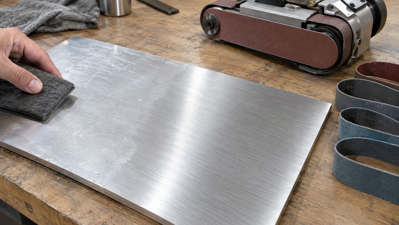
Brushed aluminum finishing is a controlled abrasive process, not a last-minute cosmetic repair. Abrasive media cut directional micro-grooves into the surface, and the final result depends on the complete recipe stack-up, including alloy, existing milling marks, grit progression, pressure, feed, measurement direction, and downstream coating. A drawing that defines only appearance leaves too much to operator judgment.
Table of Contents
Choosing the Right Brushing Method for the Part- Match the process to the surface
Process Workflow and Recommended Parameters- Six controlled steps
Masking, Anodizing, and Post-Finish Behavior- The coating changes the measured surface
Inspection and QA Checkpoints That Hold the Line- Build the inspection sequence
DFM Tips and Common Troubleshooting Cases- Start with alloy and machining behavior
Why Brushed Aluminum Finishing Starts with the Spec
A brushed enclosure can pass a visual check as bare aluminum and fail after anodizing. The usual cause is an incomplete finish stack: the alloy, milling marks, grit sequence, grain direction, roughness target, and coating were never specified together. Set those inputs before abrasive contact. A machined 6061 face, formed 5052 panel, and harder 7075 component can need different pressure and feed control even when the requested grain looks similar.
The roughness callout gives the supplier a measurable starting point. Surface-finish references commonly place a standard #4 brushed finish at about 40–50 µin Ra, or roughly 1.0–1.3 µm Ra, a finer sanitary brushed finish around 32 µin Ra, or about 0.8 µm Ra, and a coarse #3 brushed finish around 40–60 µin Ra, approximately 1.0–1.5 µm Ra. These values are summarized in the surface finish guide for aluminum components.
Ra is the arithmetic average deviation of the measured profile from its mean line. Rz records the vertical distance between selected peaks and valleys, so it can expose an isolated deep scratch that an average Ra value hides. Measure across the grain when checking a directional finish, and define the inspection direction on the drawing. A part may meet Ra while still showing a groove that affects sealing, appearance, or fit.
Four inputs belong on the drawing
- Alloy and temper. State the material grade and condition. Hardness, ductility, and smearing response change how much pressure the abrasive needs and how readily it removes or displaces material.
- Grain direction. Define longitudinal, circular, or cross-direction brushing from a datum or visible edge. Coordinate the direction across adjacent panels, especially where a corner, seam, or mating face makes a directional break easy to see.
- Ra and, where needed, Rz. A “satin” note alone leaves the supplier to choose the texture. Industry guidance places satin and brushed aluminum broadly around 0.4–1.5 µm Ra, while smoother cosmetic effects may fall around 0.5–0.75 µm Ra. Use the practical guidance on brushed surface roughness to frame the target, then qualify it with a production sample.
- Downstream coating. Specify Type II anodizing, hardcoat Type III, clear sealing, lacquer, or no coating. Bare-metal roughness is not the final acceptance condition. Anodizing can change color uniformity and emphasize directional marks, while sealing affects protection and the appearance of fine scratches.
A common machined baseline is 125 µin Ra, or 3.2 µm, per ASME B46.1 surface-texture guidance. Brushing must therefore be planned as a controlled change from the machined condition, not as a cosmetic pass applied after every other decision. Ra terminology also follows common ASME B46.1 and ISO 4287:1997 standards language, allowing drawings and supplier reports to use the same definitions. For drafting conventions, use the surface texture callout guide.
| Spec Input | Common Values | Effect on Brushing | Risk if Underspecified |
|---|---|---|---|
| Alloy and temper | 6061, 5052, or other specified grade | Determines cutting response, smearing tendency, and pressure sensitivity | Uneven grain or excessive material removal |
| Grain direction | Longitudinal, circular, or cross-direction | Controls visual flow and inspection orientation | Mismatched panels or visible directional breaks |
| Roughness | Ra target, with Rz where scratch depth matters | Establishes measurable texture depth | Appearance becomes operator-dependent |
| Post-finish | Type II, Type III, seal, lacquer, or none | Determines the final texture, color, and protection | Coating changes the result beyond acceptance limits |
Choosing the Right Brushing Method for the Part
The right method depends on geometry, lot size, access, and required grain repeatability. Manual brushing can produce an attractive prototype, but it isn't a reliable production process when several operators must create matching faces. Machine brushing and controlled belt processes usually win on flat parts because they hold direction and contact more consistently.
Match the process to the surface
Manual pads and hand sanding work well for prototypes, rework, and selective grain on small accessible faces. Scotch-Brite-style pads or abrasive sheets give the operator good control around edges, but hand pressure, stroke overlap, and stopping position vary. Use a sanding block on flat faces when possible, and don't expect a hand-finished corner to match a wide-belt surface without a defined reference coupon.
Rotary and through-feed machine brushing suit flat sheets, plates, and extrusions where the grain must remain linear across a batch. Wheel heads using Tampico, sisal, or abrasive-impregnated nylon can produce repeatable direction when the part presentation and contact arc stay fixed. Machine brushing is the practical choice when appearance must remain consistent across repeated components.
Belt sanding handles heavier stock removal, weld-blended regions, sheared edges, and existing surface defects. Aluminum-oxide belts cut more aggressively, while non-woven belts tend to produce a softer conditioning effect. Belt sanding is powerful, but it can erase an edge or change a fit surface if the operator uses excessive pressure.
Orbital or jitterbug sanding with abrasive pads reaches contoured CNC pockets and surfaces that a wheel can't contact evenly. It offers access, not automatic uniformity. The pad's orbit can leave visible swirls if the final grain pass doesn't establish one direction.
Vibratory or tumble finishing is useful on small 3-axis parts before the directional step. Ceramic media and a light abrasive compound can soften milling marks and reduce manual cleanup, but tumbling won't create a controlled linear grain on an exterior face. Treat it as preparation, not the final brushed aluminum finishing operation.
The CNC machining resource for aluminum parts can help teams evaluate whether the machined geometry is suitable for a secondary directional finish before committing to a production route.
| Method | Best Geometry | Lot Size Fit | Grain Consistency | Typical Ra Range (µm) |
|---|---|---|---|---|
| Manual pad or sheet | Small flat faces, selective rework | Prototype and low volume | Operator-dependent | About 0.5–1.5, depending on abrasive and pressure |
| Machine wheel | Flat sheets and extrusions | Repeated production lots | High with controlled setup | About 0.8–1.5 |
| Belt sanding | Flat stock, edges, weld blends | Low to high volume | High on accessible faces | About 1.0–1.5 for coarse-to-satin work |
| Orbital abrasive pad | Contoured pockets and irregular faces | Prototype to moderate volume | Moderate, requires directional final pass | About 0.5–1.3 |
| Vibratory or tumble preparation | Small parts with interrupted surfaces | Batch processing | Not suitable for final linear grain | Process-dependent, use a measured target |
A flat panel and a deep pocket shouldn't share the same finishing instruction merely because both are aluminum. Pick the abrasive path that can physically maintain contact and direction on the actual geometry.
Process Workflow and Recommended Parameters
A repeatable process starts with a clean surface and ends with protected parts. The following workflow gives a shop a usable baseline, but the supplier still needs to validate the recipe against the alloy, geometry, and final coating.
Six controlled steps
- Degrease before abrasion. Use an alkaline cleaner at 40–60 °C for 3–5 minutes, then rinse and dry. These values come from the supplied practical process guidance. Coolant residue and fingerprint oil can glaze an abrasive belt, transfer contamination into the grain, and create adhesion problems under anodizing.
- Establish a workable machined baseline. Don't ask a 320-grit belt to remove deep face-milling peaks. On 6061-T6, a sharp insert and controlled milling can leave feed marks under 0.05 mm, giving the brush a realistic chance to erase the pattern rather than trace over it. The broader engineering guidance on surface-finish targets before anodizing places many pre-anodizing finishes between 0.8 and 1.6 µm Ra, with tighter values used where cosmetics or function demand them.
- Rough-cut only when needed. Use 120–180 grit aluminum-oxide or non-woven abrasive at 15–25 m/s belt speed and 2–4 m/min feed, applying light contact pressure. This stage removes prior defects and establishes the direction. Stop as soon as the old pattern disappears. More dwell time isn't a substitute for a better incoming surface.
- Refine the grain. Move to 240–320 grit at the same belt-speed range, but slow feed to 1–2 m/min. The slower pass evens out scratch depth and reduces the visual variation left by the roughing stage. Avoid skipping directly from coarse abrasive to fine abrasive because the fine pass may polish the peaks while leaving deep valleys behind.
- Apply the final conditioning pass. A 400–600 grit Scotch-Brite or non-woven web can create the softer satin effect often requested on consumer enclosures. Use consistent overlap and keep the tool path aligned with the drawing direction.
- Clean and protect. Rinse, dry, inspect under raking light, and use interleaving paper during handling. Bare parts shouldn't rub against one another after finishing because contact can create streaks that are difficult to distinguish from process defects.
For wheel brushing, a practical setup uses a 200 mm wheel at 1450 RPM, with a 6–10 mm contact arc and 1–2 mm depth of cut per pass. These process values should be recorded alongside abrasive type, pressure, orientation, and inspection method. The supplied guidance notes that a 10% change in belt speed can shift Ra by 0.1–0.2 µm, so speed changes must be treated as process changes, not operator preference.
| Step | Abrasive / Grit | Belt Speed (m/s) | Feed Rate (m/min) | Expected Ra (µm) |
|---|---|---|---|---|
| Degrease and prepare | Alkaline cleaner | Not applicable | Not applicable | Existing surface retained |
| Rough-cut | 120–180 grit | 15–25 | 2–4 | About 1.0–1.5, depending on substrate |
| Intermediate refine | 240–320 grit | 15–25 | 1–2 | About 0.8–1.3 |
| Final condition | 400–600 grit non-woven | 15–25 baseline | Controlled, slower pass | About 0.5–0.8 for a fine cosmetic effect |
| Wheel brushing | Specified wheel and abrasive | Set by wheel speed | Set by part presentation | Validate by profilometer |
The numbers are starting parameters, not acceptance results. Measure the first article, then adjust one variable at a time.
Masking, Anodizing, and Post-Finish Behavior
Masking determines where the brushed pattern and coating stop. A poor mask can create a sharp visual defect even when the open face is perfect. Vinyl or polyester tape is practical for straightforward boundaries, custom die-cut dots suit repeated small exclusion zones, liquid masks cover irregular regions, and plugs or caps protect tapped holes and bores. Choose the mask by edge definition, chemical resistance, and how easily it can be removed without lifting residue.
Clear anodizing is unforgiving because it preserves the visual read of the underlying grain. Black or matte anodizing can reduce the apparent contrast of a direction mismatch, but it doesn't repair an inconsistent substrate. Lacquer can protect the appearance, yet it adds its own film behavior and should be validated for edge coverage, handling, and chemical exposure.
The coating changes the measured surface
Anodizing follows the existing topography rather than replacing it with a perfectly new surface. One finishing reference reports that Type II anodizing can increase Ra by about one-third to one-half, while hardcoat can make the surface 2–3 times rougher than the bare-metal condition. The supplied roughness reference for surfaces before and after anodizing explains why the pre-finish must be selected with the coating stack in mind.
A pre-anodize target around 0.8–1.6 µm Ra is commonly discussed for aluminum finishing, with 0.8 µm Ra used where a higher-cosmetic or functional surface is required. General-purpose CNC aluminum surfaces are also commonly accepted around 1.6–3.2 µm Ra, although those broader values aren't automatically suitable for a visible brushed enclosure. The anodizing service overview provides useful context for coordinating the mechanical finish with the coating operation.
Sealing can move the reading again and may alter gloss or color perception. A hot-water seal around 50–60 °C should be treated as a controlled process stage, not an invisible afterthought. Validate the complete sequence on a representative coupon, especially when the part has sealing faces, tight threads, or close-fitting covers.
| Starting Brushed Surface (6061-T6) | After Type II Anodize | After Hardcoat (Type III) | After Hot-Water Seal | End-Use Fit |
|---|---|---|---|---|
| About 0.4–0.8 µm Ra for a fine cosmetic surface | Often rises to approximately 0.6–1.0 µm Ra | Can become substantially rougher than bare metal, potentially 2–3 times the original roughness | May shift roughness and visual gloss further | Cosmetic enclosures, wear surfaces, or marine parts require separate validation |
| About 0.8–1.6 µm Ra for controlled pre-anodize texture | Coating follows and may amplify the grain | Greater texture can affect appearance and contact behavior | Seal condition influences final appearance and measurement | Select by final Ra, corrosion needs, wear, and dimensional tolerance |
Don't approve the bare brushed part and assume the anodized part will match. Approve the finished stack-up.
Inspection and QA Checkpoints That Hold the Line
A brushed surface needs both instrumented inspection and controlled visual review. Profilometer readings verify texture, while a light-box comparison catches directional breaks, pressure bands, and streaks that a single trace can miss. Measure across the grain where appropriate, document the orientation, and use the same stylus settings and evaluation method for every comparison.
Build the inspection sequence
Start with first-article verification using a contact profilometer. The supplied inspection plan specifies a 0.8 mm cutoff wavelength and a 4.0 mm evaluation length, so those settings should be recorded on the traveler with the Ra and Rz results. If a portable gauge is used on the production floor, compare it against the laboratory instrument on overlapping test sites and confirm repeatability with a reference coupon before relying on it.
Visual checks should use a fixed reference panel and consistent diffuse lighting. Inspect the grain direction, overlap, edge transitions, and any orbit marks. In-process checks should be frequent enough to catch abrasive loading or belt wear before the lot develops a visible split between early and late parts.
Reject or hold parts showing:
- Orbit marks: Circular or jitterbug patterns interrupting the specified linear grain.
- Short or incomplete grain: The visible grain doesn't cover the required face consistently.
- Ra drift: The measured surface moves outside the approved band across parts.
- Anodize streaks: Trapped oils, uneven cleaning, or inconsistent coating exposure creates bands after anodizing.

A one-page traveler should identify the alloy and temper, grain datum, abrasive sequence, belt or wheel settings, cleaner and rinse method, pre-finish Ra/Rz, coating type, seal condition, final inspection results, operator, date, and disposition. Retain first and last pieces when the finish is highly visible. That record makes belt wear and coating drift traceable instead of anecdotal.
DFM Tips and Common Troubleshooting Cases
The best brushed aluminum finishing result is designed before the first machining cycle. Alloy, toolpath, abrasive sequence, anodize condition, masking, and fit tolerance form one chain. If an upstream decision leaves deeper peaks than the brush can remove, the coating will expose the problem rather than hide it.
Start with alloy and machining behavior
6061-T6 is a common engineering choice because it machines predictably and supports a broad range of finishing routes. 5052-H32 is more prone to smearing under aggressive abrasion, so pressure and belt loading require closer control. 7075-T6 can demand a more conservative feed and a validated abrasive recipe to prevent an overly harsh or uneven cut.
Ball-end milling also deserves attention. A stepover at or below 10% of cutter diameter can keep the toolpath pattern fine enough for a controlled brushing pass, while the supplied DFM guidance recommends keeping milling marks finer than 0.4 µm Ra when a 320-grit brush must erase them. If the incoming peaks exceed the brush cut depth, the operator may polish the tops without removing the valleys. Clear anodizing then makes the surviving tool paths obvious.
Practical rule: Brushing should refine a prepared surface, not rescue a poor machining strategy.
Four failures that recur
Visible tool paths under clear anodize. The milling pattern was deeper than the selected abrasive could remove. Rework usually requires returning to a coarser preparation stage, then progressing through the approved grit sequence. Adding pressure to the final belt often creates uneven bands and changes the edge geometry.
Zebra stripes after anodizing. Uneven pressure, inconsistent part presentation, or a loaded abrasive belt creates alternating bands of texture. The coating amplifies the difference in light reflection. Replace or dress the abrasive, stabilize contact pressure, and verify the belt path on a witness coupon before restarting the lot.
Fingerprint ghosting beneath masking tape. Coolant or handling oil trapped under the mask can remain invisible on bare aluminum, then appear as a coating defect after anodizing. Clean before masking, use gloves during handling, and control the time between cleaning, brushing, masking, and anodizing.
Thread interference after brushing. Abrasive work can close a thread's minor diameter when the process reaches an edge or internal feature. The supplied failure example identifies an M6 minor-diameter closure of 0.02 mm after brushing. Mask the thread, use a plug or cap, and verify the final fit after coating rather than measuring only the bare machined hole.
Treat the surface as a stack-up
| Upstream Decision | Effect on Brushed Surface | Effect on Anodize | Effect on Final Fit | Common Failure |
|---|---|---|---|---|
| Alloy and temper | Changes cutting response and smearing risk | Changes color and texture response | Can affect coating uniformity at edges and features | Patchy or torn grain |
| Milling strategy | Sets peak depth and directional baseline | Surviving tool paths remain visible | Material removal may alter datum relationships | Tool marks under clear coating |
| Grit sequence | Controls scratch depth and visual grain | Coating follows the prepared topography | Excessive abrasion can reduce edge or thread clearance | Zebra bands or incomplete grain |
| Pressure and feed | Controls line spacing, depth, and uniformity | Creates gloss and color variation after coating | Can remove material unevenly from sealing faces | Ra drift and pressure stripes |
| Masking | Defines protected boundaries and holes | Prevents coating or contamination in selected areas | Protects threads and mating features | Ghosting, clogged threads, poor edge definition |
| Anodize and seal | Changes final roughness and appearance | Determines corrosion, color, and wear behavior | May affect fits, seals, and sliding contact | Parts pass bare inspection but fail after finish |
The manufacturing drawing should therefore define the finish at the level of the final assembly risk. A decorative enclosure may prioritize grain continuity and clear anodize appearance. A marine panel may need coating and sealing validation. A precision housing may require protected threads, controlled sealing faces, and a final fit check after anodizing.
FIRMFG provides CNC machining, sheet-metal fabrication, anodizing, and decorative finishing, including brushed aluminum finishing with controlled directional abrasion and fine, medium, or coarse line patterns. For parts that need machining and finishing coordinated through prototype or low-volume production, visit FIRMFG and submit the drawing with the alloy, grain direction, Ra/Rz target, masking zones, and post-finish requirements.