CNC Machining for Aerospace: Materials, Tolerances, and DFM
You're staring at a drawing full of tight bores, thin walls, and a material callout that makes the buyer flinch. The schedule is already squeezed, the first article hasn't started, and procurement is asking whether the alloy can even be sourced consistently. That's the world of CNC machining for aerospace, where a good toolpath is only one piece of a larger program that has to survive qualification, inspection, and supply-chain friction.
Aerospace machining is a large and still-growing industrial segment, with US$31.3 billion projected in 2024 rising to US$43.6 billion by 2032, according to Stratview Research, while the aerospace CNC machining market is estimated at US$4.7 billion in 2024 and US$8.8 billion by 2033, based on the market figures cited in the brief (market estimate). Those numbers matter because aerospace buyers don't just want parts that cut cleanly. They want repeatable multi-axis manufacturing, traceable materials, and a process that won't collapse when one supplier slips.
Table of Contents
- Why Aerospace CNC Demands a Different Approach
The part is only as strong as the chain behind it
CNC in aerospace is a control system, not just a cutting process
Aerospace-Grade Materials and Their Machining Challenges- Titanium, Inconel, aluminum, and PH stainless steel behave very differently
Multi-Axis Machining Strategies for Complex Geometries- Choose the fewest setups that still protect the feature
Surface Finishes, Treatments, and Inspection Protocols- Finish should follow function, not habit
When to Choose CNC Versus Hybrid Manufacturing Workflows- Use CNC as the lead process when the part needs mature control
Supplier Selection Beyond Basic Machining Capability- Look for resilience, not just equipment
DFM Checklists and Procurement Workflows for Aerospace Programs- Use a DFM checklist that respects machining reality
Why Aerospace CNC Demands a Different Approach
A general machine shop can make a part look right. An aerospace program has to prove the part stays right through inspection, traceability, and release. The first question is not whether the machine can hit the dimension. It is whether the full chain, from material cert to final inspection, still holds when the program changes.
The part is only as strong as the chain behind it
Recent industry coverage says about 64% of aerospace companies were still affected by disruptions in 2025, mainly from extended lead times and material shortages. That matches what program teams see on the floor. A drawing can be manufacturable and still miss the launch date because a certified alloy, a qualified outside process, or a rework loop arrives late.
Practical rule: In aerospace, the safest supplier is often the one that can absorb revisions without forcing a full restart on material, tooling, and inspection.
The useful CNC conversation starts with risk. If the geometry is simple but the alloy is scarce, sourcing drives the schedule. If the geometry is complex but the material is stable, setup reduction and inspection planning matter more. If both are volatile, the program needs a manufacturing path that can tolerate change without breaking qualification.
CNC in aerospace is a control system, not just a cutting process
Aerospace programs live and die on repeatability, certification-ready records, and tight metrology discipline. One precision machining report states that aerospace CNC manufacturing can achieve tolerances within 0.0001 inches, or about 2.54 micrometers, and that 80% of high-precision aerospace parts are produced using CNC mills, 95% of aerospace CNC-machined parts are inspected using coordinate measuring machines, and CNC machining can reduce prototyping lead times by 30-50% compared with traditional methods. Those figures explain why aerospace teams rely on CNC so heavily. The machine is not just removing metal, it is helping build a verifiable process window.
A first aerospace program usually fails in predictable ways. Tolerances get written tighter than the feature needs. Inspection is added after the part is already designed. Procurement assumes any certified shop can source any alloy on demand.
A better approach is to treat design, sourcing, machining, and inspection as one coordinated system from the start. That matters even more when a 5-axis CNC route is competing with additive or hybrid workflows, because the right choice is often the one that reduces supply-chain risk and avoids a late-process surprise on the shop floor.
Aerospace-Grade Materials and Their Machining Challenges
Alloy choice often sets the machining plan before the first tool goes in. Titanium, Inconel, aluminum, and precipitation-hardening stainless steel each push a different balance of cutting speed, chip control, tool life, fixturing rigidity, inspection effort, and supply availability. Two parts that look nearly identical on the drawing can behave very differently on the machine and in the procurement queue.
Titanium, Inconel, aluminum, and PH stainless steel behave very differently
Titanium is one of the hardest aerospace CNC materials to machine because its low thermal conductivity traps heat in the cutting zone. NASA guidance notes that this drives high tool-tip temperatures, which accelerates tool wear and raises chatter risk, so shops usually respond with lower cutting speeds, rigid fixturing, and aggressive chip evacuation to protect tool life and surface integrity (NASA titanium machining guidance). In practice, titanium punishes weak workholding and poor chip control fast.
Inconel behaves differently. It does not just resist cutting, it can work-harden mid-cut, so a tool that rubs instead of cutting cleanly makes the next pass harder. Conservative depth of cut with stable engagement usually beats aggressive feeds on paper. Aluminum is more forgiving, but not every alloy behaves the same way. Some machine cleanly and clear chips well, while others smear or load tools if cutter geometry and coolant strategy do not match the alloy. For a practical overview of aluminum behavior, see this aluminum CNC machining overview.
Precipitation-hardening stainless steels sit in the middle. They are often chosen for strength and corrosion resistance, but they still demand disciplined tool selection and heat control. They are less punishing than titanium in some cases, yet they will still expose chatter, worn tools, or a fixture that lets the part move during the cut.
The supply chain matters here too. A material can be machinable on paper and still slow a program down if lead times, cert paperwork, or approved mill sources are tight. That is one reason first-article planning should include sourcing review, not just CAM review.
Match the process to the material, not the other way around
A tough alloy does not just increase cycle time. It changes the cost model, because tool wear, inspection burden, and scrap risk rise together.
| Aerospace CNC Material Comparison | |||
|---|---|---|---|
| Material | Machining Difficulty | Primary Challenge | Typical Application |
| Titanium | High | Heat at the tool tip and chatter control | High-stress structural and rotating components |
| Inconel | High | Work hardening and tool wear | Hot-section and high-temperature hardware |
| High-strength aluminum | Low to moderate | Chip evacuation and surface consistency | Lightweight structural parts and housings |
| Precipitation-hardening stainless steel | Moderate to high | Heat control and rigidity | Fittings, brackets, fasteners, and similar hardware |
If you are specifying aluminum for a low-risk prototype, align the geometry with the cutter strategy early. A clean alloy can still become a slow part if the pockets are deep, the walls are thin, or the chip path traps swarf. Thin sections often drive more rework than the alloy itself.
The material call also affects program risk. If a part is likely to change after test, a forgiving alloy can help protect NPI timelines. If the geometry is stable and the load path is clear, a harder alloy may be the better long-term answer even if the first route is more expensive. That trade-off is often where aerospace CNC, additive, and hybrid workflows get decided.
Multi-Axis Machining Strategies for Complex Geometries
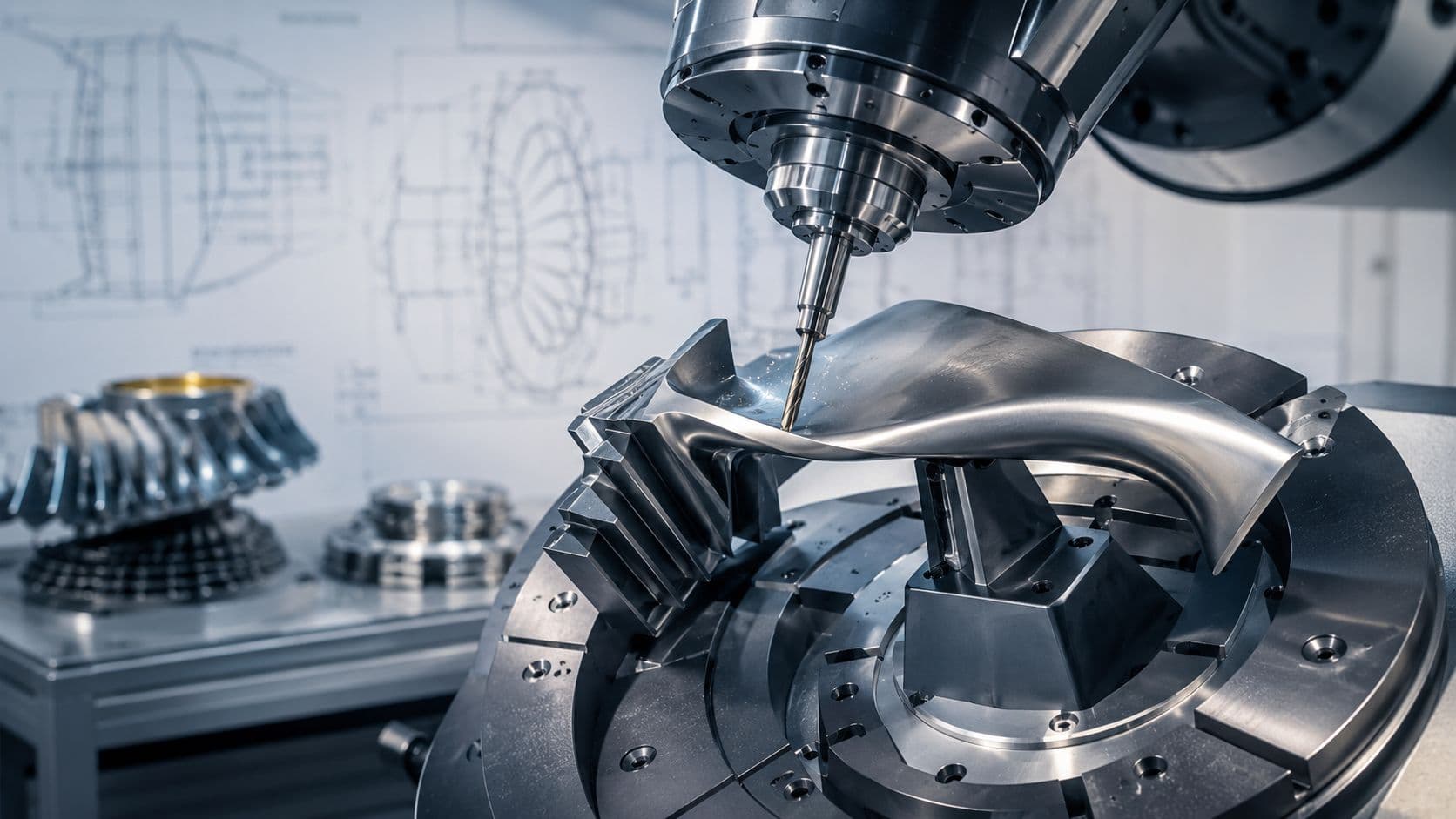
Aerospace parts break simple 3-axis assumptions fast. Curved ducts, deep pockets, blade-like surfaces, and intersecting features force the cutter to work around the part, not just down into it. The decision is usually not machine brand or spindle power, but whether the program should use 3-axis, 4-axis, 5-axis, or mill-turn so the geometry stays controllable.

Choose the fewest setups that still protect the feature
A 3-axis mill fits parts whose critical faces are easy to reach from standard orientations. A 4-axis setup helps when several sides can be reached by rotation instead of re-clamping, especially on round or repeatable features. A 5-axis simultaneous machine matters when the cutter has to stay tangent to a compound surface or reach geometry that would otherwise force extra fixtures.
Indexed 3+2 machining is often the better call when the part is complex but the tool does not need continuous motion during the cut. It cuts setup count without paying for unnecessary simultaneous motion. That matters because each re-fixture adds alignment risk, changes tool stick-out, and gives error another place to stack up.
Mill-turn makes sense when roundness matters
Rotational aerospace parts, including shafts, bushings, and similar hardware, often fit mill-turn centers because turning and milling happen in one clamping cycle. That improves concentricity and reduces handoffs. It also helps preserve datum relationships that often get lost when a turned feature moves to another machine and gets re-indicated.
Process insight: If the part has one or two critical datums, spend your complexity budget protecting those datums, not on showing off simultaneous motion.
The hidden cost in multi-axis work is usually inspection, not spindle time. A clean-looking toolpath can still fail if the shop needs special fixtures, too many setup requalifications, or repeated checks to chase datum drift across operations. Supply-chain risk matters here too. A program that depends on one highly specialized 5-axis cell can stall if that cell is booked, while a simpler routed part may move faster through a broader vendor base. For teams weighing that trade-off, this 5-axis CNC milling guide gives a practical view of what the machine can and cannot cover.
Surface Finishes, Treatments, and Inspection Protocols
Aerospace surface finish is functional. It affects fatigue performance, sealing, corrosion behavior, and whether the part will pass metrology without surprise rework. A bearing seat, a sealing face, and a structural bracket do not deserve the same finish spec, and they should not follow the same inspection plan.
Finish should follow function, not habit
General aerospace hardware often carries surface-finish limits around 125 microinches Ra on broader surfaces and 250 microinches Ra on less critical ones, while precision machining work can call for dimensional control in the ±0.0001–0.0005 in range on critical features (NASA fabrication tolerances). Those numbers only matter when they are tied to the feature's job.
A bearing seat needs tighter process control than a cover plate. A sealing face needs surface integrity and flatness that support the seal stack. A structural bracket may tolerate a rougher finish if it is carrying load instead of sliding against another surface. Write the finish spec around the actual function, or you will pay for polishing that adds cost without improving the part.
Sequence the secondary processes carefully
Shot peening, anodizing, and passivation can improve aerospace hardware, but they also change size and inspection results. If the sequence is wrong, a part can pass machining and fail after treatment. Lock down the order of operations before the first article leaves the machine.
Shop-floor reality: The hardest parts to release are often the ones that were “just a little” overcontrolled in the drawing and then reworked after finishing.
Inspection has to follow the same logic. Coordinate measuring machines are standard on precision aerospace work, but they only help if the datums, feature priorities, and acceptance criteria were clear from the start. First article inspection should verify the drawing intent, the actual finish sequence, and the traceability package together. If the paperwork and the part disagree, release slows down, it does not get safer.

When to Choose CNC Versus Hybrid Manufacturing Workflows
Pure CNC is still the right answer for many aerospace parts, especially when the geometry is mature, the alloy is demanding, and the program needs stable release conditions. But low-volume aerospace work often benefits from hybrid workflows, where additive manufacturing, vacuum casting, sheet metal, or rapid tooling handle the parts of the program that CNC shouldn't own by itself.
Use CNC as the lead process when the part needs mature control
If the part is a structural bracket, a fitting, a precision housing, or a rotating component with stable geometry, CNC should usually lead. It gives better dimensional control, clearer inspection paths, and fewer surprises on hard metals. That's especially true when the program is already comfortable with the material and the design won't keep changing.
Use hybrid methods when the schedule is the real risk
Additive manufacturing can create near-net shapes that CNC then finishes to tolerance. That works well for complicated low-volume parts where removing all the excess metal by machining would cost too much time or scrap too much material. Vacuum casting can bridge prototype and bridge-build needs when you're validating form, fit, and assembly before committing to production tooling. Sheet metal fabrication still makes sense for enclosures, brackets, and non-massive assemblies where formed sheet is faster than machining from billet.
The decision isn't about purity. It's about whether the extra operations reduce overall program risk. If hybrid steps cut lead time, lower material waste, or avoid requalifying a fully machined design every time the print changes, they can be the better choice even when a CNC-only quote looks cheaper at first glance.
Don't ignore the inspection penalty
Every added process brings its own verification burden. Additive parts need post-processing and controlled finishing. Cast parts need consistency checks. Hybrid assemblies need fit verification between processes. The cleanest program is the one where the engineering team chooses the fewest processes that still protect schedule and certification.
If the design is still moving, don't lock the whole program into a single subtractive route too early.

Supplier Selection Beyond Basic Machining Capability
A shop can own the right machine and still be the wrong supplier for aerospace work. The deeper question is whether that supplier can keep material flowing, hold inspection discipline, and handle design changes without turning every revision into a new program. That's where a lot of aerospace sourcing decisions go wrong.
Look for resilience, not just equipment
Dual sourcing and supplier localization matter because aerospace programs still feel disruptions. If a supplier can't source certified stock reliably, the rest of the capability list doesn't matter much. The same is true if they need long lead times every time a drawing revision lands. A partner that can localize material and keep buffers on critical inputs reduces schedule fragility before the first chip is cut.
Ask how they handle change
The best suppliers don't just quote the print, they explain how they'll manage revision control, reinspection, and requalification triggers. That's especially important for low-volume aerospace work, where a change to a hole callout or datum scheme can ripple into tooling, inspection, and paperwork. A strong supplier should be able to absorb engineering changes without forcing the program back to square one.
One option, not the only option
A partner such as FIRMFG can support CNC machining, additive, sheet metal, molding, and casting in one workflow, which can matter when a program needs both machined parts and bridge-build support. The useful part of that model isn't the breadth alone, it's the ability to keep more of the process under one quality and scheduling umbrella.
The right sourcing question is never “Can they machine it?” It's “Can they keep the part moving when the material, the drawing, or the schedule changes?”
DFM Checklists and Procurement Workflows for Aerospace Programs
The cleanest aerospace programs are the ones that make manufacturability decisions before the RFQ, not after the first failed article. A good DFM review prevents expensive geometry, weak datums, and inspection ambiguity from getting baked into the release package. It also gives procurement a cleaner basis for supplier comparison.
Use a DFM checklist that respects machining reality
- Wall thickness: Keep thin walls intentional, because they drive deflection, chatter, and handling risk.
- Corner radii: Match internal radii to the cutter access you can buy and maintain.
- Tool access: Check whether the critical faces need 3-axis access, indexed access, or full 5-axis motion.
- Tolerance stacking: Tighten only the features that carry function, not every dimension on the print.
- Material selection: Choose the alloy with the full machining and sourcing picture in mind, not just the catalog properties.
For tolerance discipline and release planning, this guide to CNC machining tolerances is a useful companion when the drawing starts turning every feature into a critical one.
Map the procurement flow before you send the RFQ
RFQ, review, first article, production release. That's the sequence, but each handoff needs a decision gate. Before RFQ, confirm the drawing, revision level, critical characteristics, and inspection expectations. Before first article approval, make sure the supplier understands which features are functional and which are cosmetic. Before production release, verify that material certs, process certs, and inspection records are aligned with the actual part.
Best practice: Don't wait for the supplier to ask what's important. Mark critical features, finish requirements, and revision boundaries in the package the first time.
If the team gets those steps right, the procurement conversation changes. Buyers stop asking only about unit price and start comparing risk, responsiveness, and program fit. That's the shift that keeps aerospace CNC programs moving.
If you're planning a first aerospace CNC release, FIRMFG can support the work with CNC machining, multi-process prototyping, and low-volume production under one roof. Visit FIRMFG to review its aerospace machining capabilities and start a DFM conversation before your next RFQ goes out.