Sheet Metal Fabrication Definition and Practical Guide
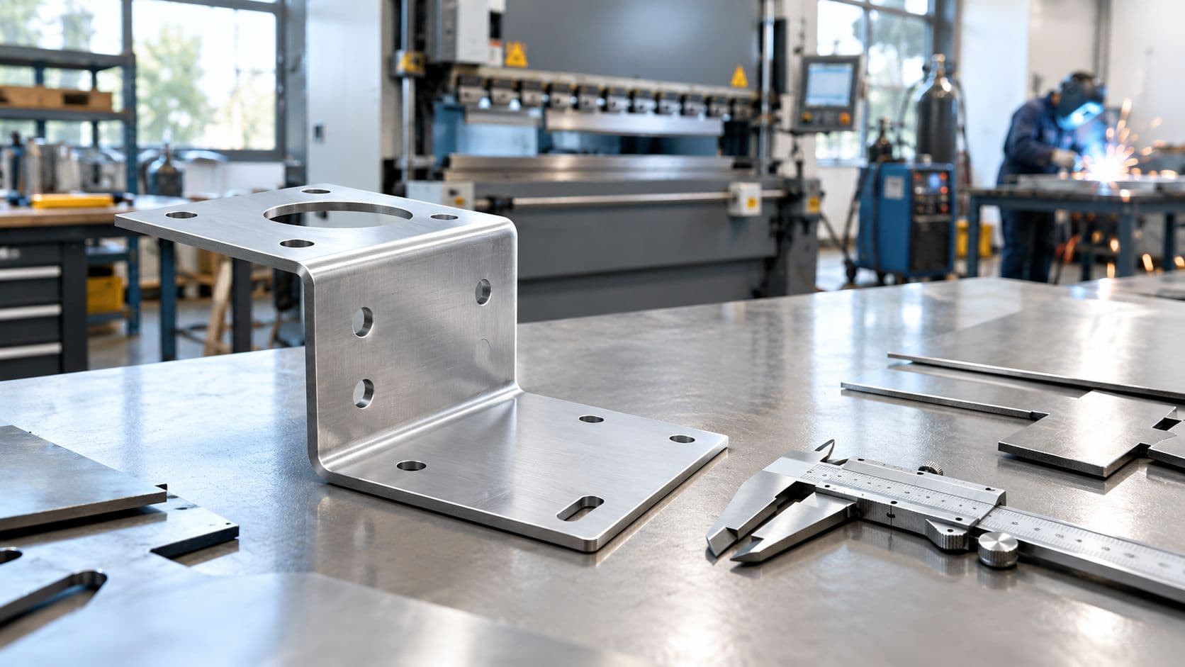
You've got a control enclosure on the bench, a bracket in one hand, and a drawing that says “sheet metal” in the title block. The question isn't whether the part is thin enough to count, it's whether sheet metal fabrication is the right manufacturing route for the geometry, the tolerance stack, and the quantity you need. That decision is where good designs stay cheap, and where bad ones turn into rework.
Table of Contents
- What Sheet Metal Fabrication Really Means in Practice
Think process family, not thickness trivia
Where the boundary becomes useful
The Core Processes That Shape Every Sheet Metal Part- Cutting and punching start the geometry
Choosing the Right Material for the Job- Match the alloy to the environment
Thickness, Tolerances, and the Boundaries That Decide What Counts- Why bends change the drawing
Design Rules That Keep Sheet Metal Parts on Budget- Start with bend geometry
Sheet Metal Compared to Other Manufacturing Methods- Use geometry and volume to choose the process
How an Integrated Partner Supports Prototyping to Production- One part, one workflow, one quality record
Putting It All Together for Your Next Sheet Metal Project
What Sheet Metal Fabrication Really Means in Practice
A sheet metal fabrication definition starts with flat stock, then turns it into a finished part through cutting, bending, punching, joining, and finishing. Industry references commonly treat sheet metal as material under 6 mm thick, with practical guidance often placing the working range around 0.020 to 0.250 in. because behavior changes once you move outside it, especially in bend force, springback, and edge control. Sheet metal basics and thickness context and process and thickness guidance

Think process family, not thickness trivia
A designer usually starts with a shape, not a material class. If the part is mostly flat, has formed flanges, and looks like an enclosure, bracket, chassis, or panel, sheet metal is often the right family because it is optimized for repeatable 2D-to-3D geometry rather than carved-from-solid complexity. The same supplier may cut, punch, bend, weld, and finish the part, so the decision is less about a single thickness cutoff and more about which combination of operations fits the part cleanly.
That's why a bent aluminum enclosure and a machined aluminum block solve different problems. The enclosure wants fast layout, flat pattern development, and predictable bends. The block wants subtractive precision and internal geometry that sheet metal can't produce without added assemblies or secondary features.
Practical rule: choose sheet metal when the part is mostly prismatic, the wall thickness stays uniform, and the design can tolerate formed geometry instead of sculpted 3D surfaces.
Where the boundary becomes useful
The boundary matters because it tells you what to ask the shop. A formed cover, a control box, and a mounting bracket all fit squarely inside sheet metal fabrication. A deep pocket, a freeform contour, or a heavy block with internal cavities usually doesn't.
That's the true value of the definition. It isn't a textbook label, it's a screening tool that helps you decide whether to stay in the sheet-metal lane, move to machining, or split the part into an assembly. If the answer is unclear, the first engineering question should be, “Can this be made from flat stock with controlled bends and acceptable tolerances?” The next question is, “Will that stay true once holes, flanges, welds, and finishes are added?”
The Core Processes That Shape Every Sheet Metal Part
A sheet metal part doesn't appear all at once. It moves through a chain of operations, and each one changes what the next step can do. If you understand that chain, the part gets easier to design and cheaper to quote.
Cutting and punching start the geometry
Cutting is the first transformation. Laser, plasma, waterjet, and shear all slice flat stock, but the laser has become the go-to method for thin stainless and aluminum because it produces clean profiles and supports tightly nested layouts. It functions as a precision paper cutter, reading a digital file instead of a ruler.
Punching adds holes, notches, and louvers in a single setup, which is useful when the part needs repeated features across a run. A turret punch works a bit like a hole-punch on a stack of paper, except the “stack” is sheet metal and the machine can combine forms, slots, and cutouts before the sheet ever reaches the brake.
Bending and welding turn flat stock into structure
Bending is where the part stops being flat and starts becoming an enclosure, bracket, or frame. A press brake folds the sheet along a controlled line with a V-die, much like creasing cardboard with a ruler, except the springback has to be predicted and compensated. If you need a deeper practical view of this step, the press brake workflow is summarized in the bending process guide.
Welding comes in when the design needs a subassembly instead of a single bent blank. TIG is common on stainless and aluminum, MIG is common on mild steel, and spot welding works well for sheet-only stacks. The joining method matters because it changes distortion, finish quality, and how much post-processing the part will need.
Design insight: every bend and weld introduces a new variable, so the best sheet metal parts are usually the ones that need fewer of both.
Finishing closes the loop
The part isn't done when it comes off the brake or the welding table. Deburring, powder coating, anodizing, and plating are the steps that turn a usable shape into a usable product. They protect edges, improve handling, and help the part survive its actual environment instead of only its drawing. In real projects, the finish is often where cosmetic expectations and corrosion requirements finally meet.
Choosing the Right Material for the Job
Material choice in sheet metal work is less about abstract strength charts and more about the environment the part will live in. A bracket inside a sealed product has different needs from a marine enclosure, and a lightweight electronics chassis behaves differently from a welded utility cover. That's why designers should start with use case, not with the alloy number.
Match the alloy to the environment
Cold-rolled steel is the default for indoor brackets and enclosures because it's easy to weld, easy to paint, and usually straightforward to source. Hot-rolled steel makes more sense when the design is drifting toward heavier plate work, though the mill scale finish means it usually needs more surface prep. Stainless 304 fits many corrosion-prone enclosures, while 316 earns its place where chloride exposure, marine conditions, or medical cleaning cycles make standard stainless less comfortable.
Aluminum 5052 is the workhorse when you need a light part that still bends and welds well. 6061 brings stiffness, but it's less forgiving in the brake, so a design that looks clean on paper can become more difficult to form in the shop. Galvanized and galvanneal steel are often chosen when corrosion resistance matters more than paint-prep simplicity.
Practical rule: if the part must be light, choose aluminum first. If it must survive aggressive cleaning or corrosion, stainless is usually the safer starting point. If it lives indoors and cost matters most, mild steel is still hard to beat.
Common Sheet Metal Materials Compared
| Material | Typical Use Case | Formability | Weldability | Relative Cost |
|---|---|---|---|---|
| Cold-rolled steel | Indoor brackets, housings, painted covers | Good | Good | Low |
| Hot-rolled steel | Heavier fabricated parts, plate-adjacent work | Fair | Good | Low to medium |
| Stainless 304 | General corrosion-resistant enclosures | Good | Good | Medium |
| Stainless 316 | Marine, chloride, medical environments | Good | Good | Higher |
| Aluminum 5052 | Panels, electronics chassis, lightweight covers | Very good | Good | Medium |
| Aluminum 6061 | Stiffer structural parts, machined hybrids | Fair to good | Fair to good | Medium |
| Galvanized steel | Corrosion resistance with protection already on the sheet | Good | Fair | Low to medium |
| Galvanneal steel | Paint-ready corrosion-resistant parts | Good | Fair | Low to medium |
Cost, weight, and finish are the three key factors designers consider. Once you know which one matters most, the alloy choice gets much easier.
Thickness, Tolerances, and the Boundaries That Decide What Counts
A flat blank can look simple on screen, then turn into a different part once bends enter the design. Thickness is where sheet metal fabrication stops being a loose label and becomes a process boundary. Bending stretches the outer face, compresses the inner face, and shifts holes and edges away from their flat-pattern locations. That is why tolerance choices have to follow bend behavior, not just the nominal dimensions on the print.
Why bends change the drawing
General practice often uses ISO 2768-mK when a drawing does not define part-specific limits, because the medium class gives the shop a workable default for linear and angular dimensions. Practical bend accuracy is often around ±1° for standard work, while bend-to-hole and bend-to-edge relationships commonly sit around 0.015 to 0.030 in. because each bend adds elastic recovery and datum shift. General tolerance guidance for sheet metal
A hole placed on a flat blank and the same hole measured after forming do not behave the same way. The flat laser-cut geometry can be very consistent, while the formed part inherits bend stretch, springback, and location shift. Designers who treat those as equivalent often discover the problem only at fit-up or inspection.
Use the tolerance class as a budget signal
The point of ISO 2768-mK is not just compliance. It is a budget signal. A looser default reduces inspection friction and gives the shop room to work with normal process variation. Tighter calls on formed features force more compensation, more setup care, and often more inspection time.
A useful boundary is simple. Flat laser-cut features are easier to hold than formed features, especially after multiple bends. Once a part has several bends, cumulative error becomes the main risk, not any single feature. Critical hole patterns, edge distances, and flange lengths should be checked against the bend plan before release, the same way a machinist checks stack-up before cutting a tricky pocket.
| Feature | Fine (mK) | Medium (mK) | Coarse (mK) |
|---|---|---|---|
| Linear size on flat laser-cut features | Tighter than standard default | Common default | Looser for noncritical geometry |
| Bend angle | Tighter than standard default | About ±1° practical control | Looser for cosmetic or nonfunctional bends |
| Hole location near bends | Tightest only with extra compensation | Commonly around 0.015 to 0.030 in. relationship tolerance | Looser where fit isn't critical |
If a drawing asks for tight formed-feature control without explaining why, stop and challenge the requirement. The part may still be possible, but the process will cost more and take more attention.
Design Rules That Keep Sheet Metal Parts on Budget
Most cost problems in sheet metal start as design choices, not shop mistakes. A small bend that's too tight, a hole that's too close to a flange, or a flange that's too short for the brake tooling can push the part into rework before the first good article is made. These rules are the ones that matter most because they map directly to shop-floor effort.
Start with bend geometry
For cold-rolled steel and stainless, the inside bend radius should usually match the material thickness. Going below 1× thickness is where the design starts demanding a tighter punch, more careful setup, and a higher risk of cracking or ugly edge response. The bend is not just a line on the print, it's a physical deformation zone that needs room to happen.
Flange length matters just as much. If a flange is too short, the press brake tooling can't grip or form it cleanly. A good rule of thumb is to give the form enough length to behave predictably rather than forcing a borderline shape that depends on operator luck.
Respect hole and edge spacing
Hole size and location create another budget trap. If the hole diameter is too small relative to thickness, tool breakage and burr control get harder fast. Holes too close to a bend line distort during forming, so the hole-to-bend distance needs real attention during layout, not after release.
Use slots instead of round holes when hardware clearance matters and the exact shape of the opening can flex a little. A slot gives the designer more tolerance stack relief. Round holes look cleaner on paper, but they can be less forgiving once the part has been formed.
- Bend radii: Keep the inside radius aligned with material thickness unless the process needs a tighter callout.
- Hole sizes and spacing: Leave enough room between holes, bends, and edges so the material doesn't tear or distort.
- Flange lengths: Make sure the brake can physically form the edge without tool interference.
- Corner relief: Add radii or notches where internal corners would otherwise concentrate stress.
Shop-floor rule: if a feature forces the operator to “save” the part by hand, the drawing probably asked for too much.
Save complexity for features that earn it
Louvers, dimples, and hems all have value, but they're not free. Louvers and dimples add operations. Hemmed edges can be cheaper than trying to deburr a sharp, exposed edge after the fact, but only when the design is already set up for that forming sequence. The best budget parts are the ones that use complexity where it pays back in assembly or safety, not where it just makes the flat pattern harder to nest.
Sheet Metal Compared to Other Manufacturing Methods
Sheet metal is not the universal answer. It wins when the part wants uniform walls, repeatable bends, and a flat pattern that can be nested efficiently. Once geometry gets more sculpted, thickness grows, or the quantity drops, another process can beat it on cost or lead time.
Use geometry and volume to choose the process
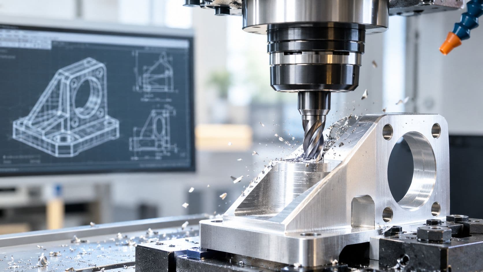
CNC machining is the better choice for thick blocks, deep pockets, or complex 3D contours that can't be created cleanly from sheet. It also tends to fit low-volume precision parts, especially when the run is under about 10 units and the design hasn't stabilized yet. Plate fabrication takes over when thickness climbs beyond standard sheet territory or the part becomes too large for typical sheet stock, since weldments from cut plate are often more practical there.
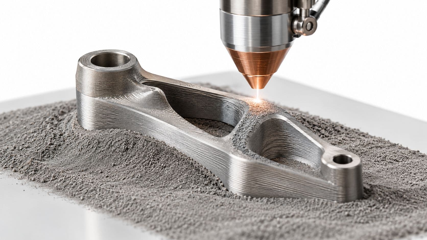
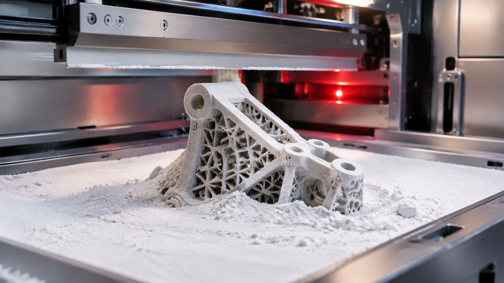
3D printing belongs in the prototype and fixture world when geometry is highly complex, when you need one-off validation, or when topology matters more than finish. It doesn't replace sheet metal for production enclosures, but it can answer early questions before metal tooling ever starts.
Sheet Metal vs. Machining, Plate Fabrication, and 3D Printing
| Method | Best Thickness | Typical Volume | Lead Time | Per-Part Cost |
|---|---|---|---|---|
| Sheet metal fabrication | Thin, uniform stock | Small to medium, especially repeat runs | Usually short when the part is bend-friendly | Lower when geometry is flat-friendly |
| CNC machining | Thick blocks and complex 3D shapes | Low volume, often under 10 units | Varies with complexity | Higher on simple parts, justified by geometry |
| Plate fabrication | Thicker material and large weldments | Low to medium | Varies by weld and prep load | Often efficient for heavy structures |
| 3D printing | Prototypes and highly complex forms | One-offs and small validation batches | Fast for concept work | Best for validation, not metal-equivalent production |
A simple rule helps: if the part is mostly flat, bends are doing the structural work, and the quantity justifies setup, sheet metal is probably the right path. If the part is a block, a sculpture, or a very small run of highly precise parts, look elsewhere first.
How an Integrated Partner Supports Prototyping to Production
A single sheet metal bracket can pass through three or four vendors before anyone agrees the fit is right. One shop cuts the blanks, another bends them, another finishes them, and someone else handles inspection. Every handoff adds delay, and every delay creates a new chance for the revision to miss the next build window.

One part, one workflow, one quality record
A better path starts with DFM review on day one. The engineer sends a STEP file, the fabricator checks bend access, hole spacing, material fit, and tolerance risks, then the order moves into sourcing and setup with the same revision already in view. If the part needs finishing or assembly, those steps stay in the same system instead of becoming separate projects.
That matters because the quality record stays together too. Inspection data, certificates, and release checks remain tied to the same work order, which gives the design team one place to resolve issues instead of chasing answers across multiple vendors. Prototype sheet metal fabrication workflow
What the engineer actually feels
The experience is simpler than the supplier list suggests. The engineer reviews the part's dimensions, gets feedback on bend feasibility, accepts a material choice, and sees the build move toward prototype and production on the same floor. If a revision is needed, it doesn't have to bounce between outside companies before someone updates the tooling or the inspection plan.
FIRMFG is one example of a partner that combines sheet metal fabrication with CNC machining, 3D printing, molding, casting, and finishing, so the same team can support early prototypes and short-run builds without splitting the workflow across multiple shops. That kind of setup is useful when the part is still changing, because the handoff risk is lower and the revision loop stays shorter.
One supplier won't fix a weak design, but it can keep a good design from getting tangled in logistics.
Putting It All Together for Your Next Sheet Metal Project
Use sheet metal when the part is thin, mostly uniform, and built from flat stock that can be cut and formed into shape without forcing the process. Check the material against the environment, check the bend geometry against the brake, and check the tolerances against what changes after the first bend lands. If the answer keeps pointing back to flat patterns, flanges, and repeatable forming, you're in the right manufacturing lane.
Before you release the drawing, confirm the thickness is in the sheet-metal range, the bend radius isn't fighting the material, hole sizes and edge distances are realistic, and the tolerance scheme matches ISO 2768-mK unless a tighter callout is needed. Then choose the route that fits the part, not the one that sounds easiest in CAD. A simple 5 to 10 unit trial is often enough to expose bent-feature issues before you commit the design to a larger run.
If your next enclosure, bracket, or chassis needs a manufacturable sheet metal definition turned into a real part, talk to a shop that can review the model, bend it, weld it, finish it, and inspect it in one workflow. Visit FIRMFG to discuss the drawing, get DFM feedback, and move your next prototype toward production with fewer handoffs.