Vacuum Casting Services: A Practical Guide for Engineers
You're under a pilot-build deadline, the design has been frozen, and procurement wants parts that don't look like prototypes when they hit the table. In that moment, vacuum casting services stop being a marketing phrase and become a scheduling decision, a tolerance decision, and a supplier decision all at once. The process earns its place when 3D prints look too rough, injection tooling is still weeks or months away, and the team needs a small run of parts that can be handled, checked, and shown with confidence.
Table of Contents
- Why Engineers Reach for Vacuum Casting
- What Vacuum Casting Is
- The Vacuum Casting Process Step by Step
Master, mold, and cut line
Resin handling under vacuum
Cure, demold, finish
Resins, Wall Thickness, and Surface Finishes- Thickness drives fill behavior
Lead Times and Cost Drivers
Vacuum Casting vs Injection Molding and 3D Printing- Where each process fits
Design Rules That Prevent Rejected Molds- Draft, walls, and radii
Inspections, Certifications, and Choosing a Provider
Why Engineers Reach for Vacuum Casting
The week-before-pilot panic usually sounds the same. The CAD is locked, the buyer wants 30 units, and the parts have to survive a demo, a fit check, or a customer review without giving away that they were rushed. That is where vacuum casting gets pulled into the conversation, because it bridges the gap between rough additive prototypes and slow hard tooling.
A good vacuum-cast part gives you the look and feel of a molded component without forcing the program into steel before the design has earned it. That matters for design validation, user studies, trade-show units, regulatory samples, and short market tests. It also matters when the demo parts have to match a housing, a snap feature, or a cosmetic finish closely enough that the conversation stays on the product, not the manufacturing method.
Practical rule: if the team needs parts that must be handled like near-production pieces, but not committed to production tooling, vacuum casting is often the least disruptive path.
The other reason engineers use it is mold economics. A silicone tool is not a lifetime asset, but it can usually support a small run before it starts to degrade. In practice, that gives you enough output to clear a validation gate without paying for a steel tool that may still be wrong. Industry history also matters here, because this isn't a new, experimental process, a 2021 Wiley review described vacuum casting of reactive polymer resins in silicone molds as “one of the oldest rapid tooling methods”, and the method's roots are commonly traced back to the 1960s in Dresden and Cottbus in the former GDR, later moving into automotive work in Japan in the 1970s and broader use in the 1980s as thermoset plastics improved appearance and property replication (industry history and process background).
What Vacuum Casting Is
Vacuum casting works as a master-pattern-to-mold-to-part chain. A real part, or more often a high-resolution 3D-printed master, is used to make a silicone mold, then polyurethane or another compatible resin is cast into that cavity under vacuum. The result is not a throwaway placeholder. It is a functional cast part with cosmetic and mechanical behavior that can come close to molded plastic, depending on the resin and the geometry.

The silicone mold process is simple on the bench, but it only works well if the master is prepared properly. The master is suspended in a casting box, liquid silicone is poured around it, the silicone cures, and the mold is split so the master can be removed and the cavity formed. That flexible mold is the strength of the method, because it captures detail while still allowing demolding without the draft limits of metal tooling.
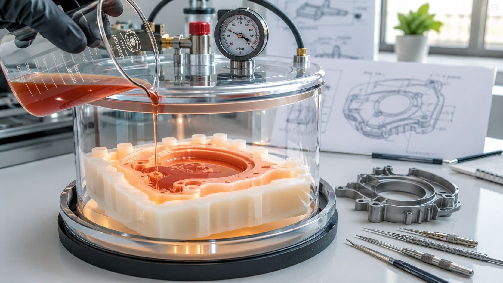
The vacuum chamber is what separates a usable cast from a reject. Pulling air out of the resin helps it flow into thin walls, ribs, and small details without trapping bubbles. That is why the process gets used for parts that need a clean cosmetic surface and consistent fill across a small batch.
The terminology on supplier sites can get muddy, so the distinctions matter. Vacuum casting is the process, urethane casting is the common material family used in the process, and RTV molding usually refers to the silicone mold itself. Traditional plaster casting is a different method altogether, and it does not deliver the same replication quality or workflow flexibility. For a process layout that matches supplier terminology, the workflow is often mapped out in more detail in this vacuum casting process reference.

The Vacuum Casting Process Step by Step
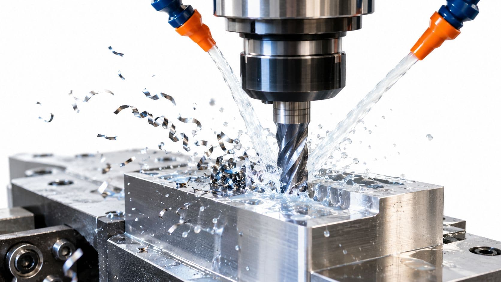
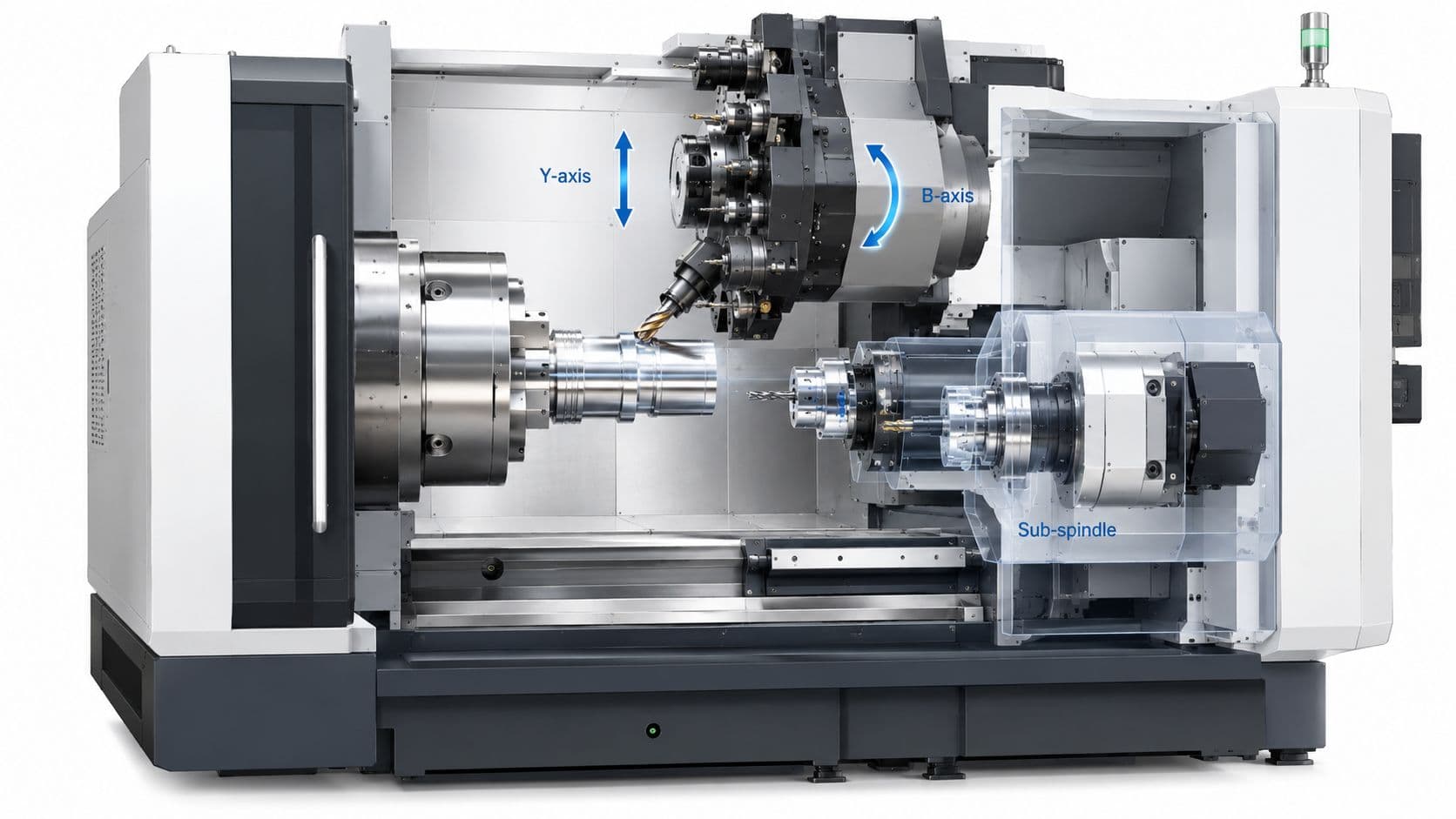
The job starts before any silicone is mixed. A master pattern gets prepared from SLA, SLS, or CNC machining, then cleaned up so the finish on the master becomes the finish on the mold cavity. If the master is sloppy, the mold will faithfully copy every flaw, so surface prep is not a cosmetic extra, it's a production input.
Master, mold, and cut line
Once the master is ready, the mold box gets built around it and RTV silicone is poured in, usually after degassing to reduce trapped air. After curing, the mold is opened carefully, the master is removed, and the cut lines, vents, and gates are trimmed. That is the point where a mold either becomes usable or becomes a maintenance headache later on.
Resin handling under vacuum
The casting resin is mixed, pigmented if needed, and pulled under vacuum again to release entrained air. The mold then goes back into the chamber, resin is drawn through the cavity, and the part fills from the venting scheme rather than from guesswork. That vacuum step is what protects small bosses, thin ribs, and blind features from filling with bubbles or short shots.
Cure, demold, finish
After the pour, the part benches out until it cures enough to demold cleanly. Then come trim, flash removal, sanding, and any paint or clear coat work that the program calls for. The shop-floor lesson is simple, if the gate plan is wrong or the resin isn't mixed cleanly, the chamber won't save the job.
Air management is the process. The vacuum chamber doesn't make a bad mold good, but it does keep a good mold from turning into a bubbly part.
Resins, Wall Thickness, and Surface Finishes
Material choice in vacuum casting is less about brand names and more about the part's job. Polyurethane systems can be selected to mimic ABS-like, PP-like, polycarbonate-like, rubber, or clear behaviors, which is useful when the team needs a casing, a snap-fit cover, a translucent lens, or a soft-touch component. The best match depends on the load path, the required feel, and whether the part is mainly for appearance, fit, or functional testing.
Thickness drives fill behavior
Wall thickness matters more than many teams expect. Industry guidance places minimum thickness for very small features around 0.75 mm to 1.0 mm, with 1.5 mm to 4 mm commonly recommended for stable flow and better strength, while small parts can sometimes go down to 0.5 mm only when the geometry is short and tightly controlled (wall thickness guidance). Uniform walls fill more predictably, cure more evenly, and reduce the risk of trapped air or distortion.
Practical rule: keep wall thickness as even as the design allows, because thick-to-thin transitions are where cast parts start acting unpredictable.
Surface finish sits on a spectrum. As-cast parts usually show a silicone seam and a matte sheen. From there, sanding, priming, and painted finishes can push the part much closer to a production-looking result. If the team wants a true cosmetic showpiece, plan for those finishing steps up front instead of assuming the mold alone will deliver it.
For resin selection and finish options, a useful internal reference is FIRMFG's vacuum casting resin page. Pigments, fillers, and metal powders can change both viscosity and the way the surface reads, so they need to be selected with the mold fill and the final texture in mind, not just the color chip.
Lead Times and Cost Drivers
Vacuum casting is fast compared with hard tooling, but it's not instant. A realistic expectation for tooling and first-off castings is often 10 to 15 working days, and the clock stretches when the master pattern takes longer, the finish spec is strict, or the inspection package is heavy. If the program needs a perfect first article, the lead time usually bends around verification, not around resin cure.

The main cost drivers are easy to name, but buyers still miss them all the time. Silicone tooling, master fabrication, resin choice, batch size, post-processing, and QA documentation all change the final number. If a supplier gives you only a per-part quote with no tooling context, you're not comparing like for like.
Small batches cost more per part because the mold setup work gets spread over fewer units. That curve softens as pull count rises, but only up to the point where the mold starts losing detail or tearing. Industry guidance commonly puts the practical mold life in the 20 to 30 cast pull range for standard use, though some vendors reinforce tooling and push farther with specific materials and process controls.
The break-even question matters more than the process brochure does. Public market summaries show vacuum casting services continuing to grow, with recent estimates ranging from about USD 2.73 billion in 2025 to USD 4.57 billion by 2033 at 6.67% CAGR (market estimate), but that still doesn't tell a buyer where the economic crossover lands for a given part. In procurement terms, the right question is whether the run is being used to save a tooling commitment, to speed validation, or to bridge to another process.
Vacuum Casting vs Injection Molding and 3D Printing
A team can waste time by choosing the wrong process for the wrong decision. The comparison comes down to batch size, tolerance, material range, and surface expectation, because those four factors drive both part quality and procurement cost.
Where each process fits
For a geometry check or a one-off fit test, 3D printing usually wins. It gives fast access to the shape, especially for internal channels or features that would be awkward to machine or cast. The trade-off is that the finish and material behavior often stay far from the final part.
Vacuum casting fits the middle ground. It is the better choice when you need parts that look production-like and still want to avoid hard tooling. In practical terms, that usually means short runs of functional prototypes or market-test batches where appearance, feel, and repeatability matter more than pure geometric freedom.
Injection molding is the next step once the design is stable and the quantity supports tooling. If the program is headed toward repeatable production, compare it with FIRMFG's low-volume injection molding reference before you commit to a silicone mold route. That comparison matters because casting can get you usable parts quickly, but it will not match the economics or material consistency of a molded thermoplastic run at scale.
Tolerance is part of the decision, but it is not the whole decision. Injection molding generally holds tighter control than casting, and casting usually lands between printing and molding for low-volume work. Material behavior matters too. Polyurethane castings can handle validation and short-run use, but they do not behave exactly like injection-molded thermoplastics under long-term UV, heat, or chemical exposure.
| Decision axis | Vacuum casting | 3D printing | Injection molding |
|---|---|---|---|
| Best batch size | Small to medium runs | One-offs and very low counts | Larger production runs |
| Surface feel | Close to production-like | Depends on process and post-finish | Production finish |
| Tooling need | Silicone mold | None | Steel or aluminum tooling |
| Design flexibility | Good, with DFM discipline | Very high | Lower once tooling is cut |
Choose vacuum casting when the program needs a finished-looking low-volume part and the design is not ready for hard tooling. Use 3D printing for geometry validation. Move to injection molding once the design is locked and the quantity justifies the tool investment.
Design Rules That Prevent Rejected Molds
A part can look perfect in CAD and still create an expensive silicone mold problem. The mold has to be pulled, split, filled, and demolded repeatedly, so the design needs to respect that whole chain instead of only the final shape.

Draft, walls, and radii
Add draft to faces that separate from the flexible mold, usually 0.5 to 1.5 degrees is enough for many features, though deeper or textured surfaces may need more. Keep walls as uniform as possible, generally in the 1.5 mm to 3 mm range for small parts, because thick polyurethane sections cure slower and are more likely to warp or hold a soft center. Where the wall changes direction, use radii instead of sharp corners so the resin doesn't stall or show heavy flow marks.
Undercuts and parting lines
Minimize undercuts unless the master is broken into pieces that can be withdrawn without tearing silicone. Put parting lines on flat, inconspicuous edges, then confirm that the master represents the final product, not just the nominal CAD file. Small holes and thin features often need to be oversized because silicone can distort them during mold use.
Good DFM starts with the release direction, not with the render.
Cosmetic priorities should be written down before the quote goes out. Grain, polish, color, labels, insert placement, and inspection expectations all affect mold prep and acceptance. For a clean RFQ, send the material target, tolerance stack, a sample master, and a short manufacturability review request before mold cutting starts. That's where most avoidable delays get removed.
Inspections, Certifications, and Choosing a Provider
Don't start supplier selection with a case study. Start with control points. Ask how the provider validates the master, how they monitor mold condition, how they mix and degas resin, and how they trace each batch from resin lot to shipped part. If a shop can't explain those basics clearly, it's not ready to support parts that need to arrive next week and still pass inspection.
For cosmetic programs, request a signed golden sample and a written acceptance sheet that covers color, gloss, grain, flash, parting line visibility, and critical dimensions. For functional parts, add hardness, density, wall thickness, insert retention, or load checks if those are relevant to the use case. Also ask what measurement tools are available, because a dimensional report only matters if the shop can back it with the right gauges and method.
Quality systems matter, but they're not a substitute for project-specific control. Review certifications such as ISO 9001 when they're relevant, then ask how the supplier handles first-article approval, change notification, nonconformance, and packaging. If the application is regulated or customer-specific, the conversation needs to include scope, audit rights, and compliance evidence, not just a logo on a web page.
One practical test is how the supplier talks about mold life and rejection handling. A solid partner will tell you what the silicone can realistically support, what happens when a part misses spec, and where the weak geometry is before money is spent. FIRMFG is one option that offers vacuum casting alongside CNC, 3D printing, and low-volume molding, which can help when a program needs to compare process routes without splitting the job across several vendors.
If you're weighing a pilot run, a bridge build, or a cosmetic prototype batch, send FIRMFG your CAD, target quantity, and finish expectations, and ask for a process recommendation that matches the part rather than the buzzword. Visit FIRMFG to compare vacuum casting with other low-volume manufacturing options and get a practical quote for the timeline you have.