Anodizing Aluminum Services: Type II vs Type III Explained
You've got a drawing that just says "anodize black," a handful of machined aluminum parts, and a supplier asking which type you mean. That short note doesn't tell anyone how thick the coating should be, whether a press fit still has to press, or whether the black on the lid must match the black on the base. Good anodizing aluminum services start by turning that vague note into a dimensional, wear, and color decision you can inspect.
Table of Contents
How Anodizing Grows a Hard Oxide Layer- What Happens on the Tank Line
Coating Thickness Classes and Size Growth- Run the Bore Example Before You Cut Metal
Sealing, Wear and Corrosion Trade-offs- Let the Dominant Failure Mode Decide
Color Matching, Masking and Batch Consistency- Questions Buyers Skip Until Assembly
How to Fit Anodizing Into a CNC Workflow- The Working Sequence
Write an Anodizing Spec and Request a Quote- What to Send With the RFQ
Type II vs Type III Anodizing at a Glance
Say you've got two aluminum parts on the same assembly. One is a bracket that gets handled, wiped down, and seen every week. The other is a sliding shaft that rubs inside a bearing for years. They can start as the same alloy, but they shouldn't get the same finish, because one fails cosmetically and the other fails by wearing away.
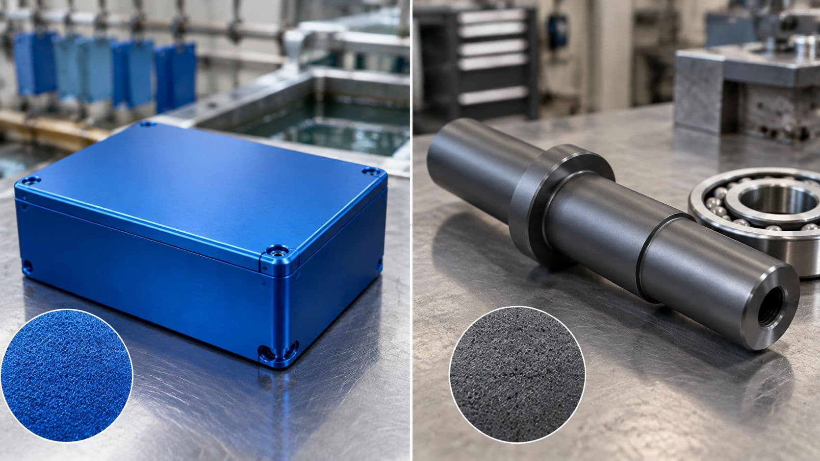
Type II is standard sulfuric anodizing for appearance and general corrosion protection. Type III, often called hardcoat, builds a much thicker and harder oxide for parts that slide, grip, or take abrasion. The trade is simple. A thicker film resists wear longer, but it also changes size more and gives you far fewer usable colors.
| Finish type | Typical film thickness | Main strength | Typical uses | Color range |
|---|---|---|---|---|
| Type II (decorative and general corrosion) | About 5 to 25 µm | Corrosion resistance and clean appearance | Consumer housings, electronics enclosures, trim | Wide range of dyed colors |
| Type III (hardcoat) | About 25 to 150 µm; 40 to 60 µm for wear parts | High hardness and abrasion resistance | Bores, sliding parts, shafts, tooling | Mostly gray, black or dark tones |
The Quick Verdict
I would choose Type II when appearance and corrosion matter most, especially for enclosures, covers, and trim that need a controlled color. I'd choose Type III when a surface works against another surface, such as a bore, guide, shaft, or tooling face.
Don't treat hardcoat as a free upgrade. It costs you tolerance, it darkens as it gets thicker, and it can round or roughen fine features that a thin decorative film would leave alone.
If the part is mainly looked at and handled, start with Type II. If it's mainly rubbed, loaded, or scraped, start with Type III and then check whether your fits can absorb the growth.
That one decision drives everything that follows. Thickness sets your machining allowance, sealing sets your corrosion and wear balance, and color sets how tightly you must control alloy and batches.
How Anodizing Grows a Hard Oxide Layer
Think of the anodic film as a honeycomb grown out of the metal itself. It's not paint sitting on top of aluminum, and it's not plating deposited from somewhere else. The shop makes your part the anode in an acid bath, drives current through it, and converts surface aluminum into aluminum oxide. That conversion is why a sound anodized film doesn't peel the way a poorly bonded paint film can.
The honeycomb matters because the oxide forms with fine pores. Those pores let dye enter before sealing, and they also explain why an unsealed film can pick up moisture and contaminants. Part of the film grows inward by consuming metal, and part builds outward beyond the original surface, which is where your dimensional change comes from.
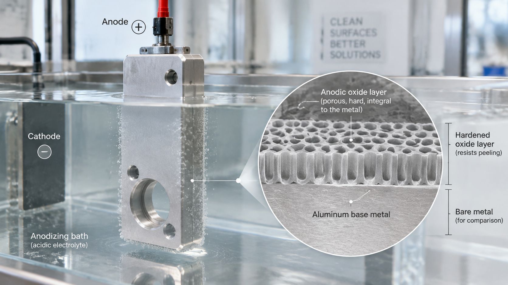
What Happens on the Tank Line
A typical line walks the part through a fixed sequence, and skipping control at any step shows up in the final finish.
- Alkaline clean and rinse: The shop removes machining oil and handling dirt so the acid sees bare, uniform metal.
- Etch: A controlled etch Levels minor differences and produces a uniform matte base.
- Desmut: This strips alloy smut left by etching, the residue that otherwise appears as blotches or streaks.
- Anodize: The part sits in a sulfuric bath at controlled current density, racked so contacts carry current without leaving burn marks on visible faces.
- Dye: If color is specified, dye enters the open pores while the film is still receptive.
- Seal: Hot water, nickel acetate, or a cold seal closes the pores and locks in dye.
- Dry and inspect: The shop checks thickness, appearance, rack marks, and any masked areas before packing.
That rack contact deserves attention on cosmetic work. Current has to reach the part somewhere, so tell the shop where a small contact mark is acceptable instead of letting the rack operator choose a show face.
Why the Process Looks the Way It Does
This isn't a new or experimental finish. Industrial anodizing was first used on an industrial scale in 1923 to protect Duralumin seaplane components, and Gower and O'Brien patented a sulfuric-acid process for cast and wrought alloys in 1927, according to the Wikipedia history of anodizing. Aircraft needed corrosion protection without the weight of heavier coatings, and sulfuric acid remains the most widely used electrolyte, which is why Type II and Type III both still come from that family.
Alloy choice rides through the whole process. 6061 usually anodizes clear and even, while 2024 and 7075 tend to darken, and high-copper castings can pit or film unevenly. Keep that picture in mind. The coating is part of the metal, so its color and uniformity follow the alloy underneath.
Coating Thickness Classes and Size Growth
A note that only says "anodized aluminum" gives a shop nothing to quote against. It doesn't state a film thickness, a class, a sealing requirement, or the size the part must measure after finishing. Two shops can both deliver anodized parts and still deliver parts that don't assemble alike.
The ASTM B580 standard listing identifies an engineering hard-coat category with a minimum film thickness of 50 µm, while architectural Class I is 18 µm, Class II is 10 µm, and limited or moderate interior abrasion categories run 3 to 5 µm. Hard anodizing overall commonly produces coatings from approximately 8 to 150 µm, with 40 to 60 µm typical for wear applications, so "hard anodize" by itself still leaves a wide range.
| Coating category | Film thickness | Size growth per surface |
|---|---|---|
| Interior, limited or moderate abrasion | 3 to 5 µm | About 1.5 to 2.5 µm |
| Architectural Class II | 10 µm minimum | About 5 µm |
| Architectural Class I | 18 µm minimum | About 9 µm |
| Engineering hard coat (ASTM B580) | 50 µm minimum | About 25 µm |
| Typical hard anodize for wear | 40 to 60 µm | About 20 to 30 µm |
Run the Bore Example Before You Cut Metal
Roughly half the film grows outward. That means each surface grows by about 50% of the specified coating thickness, so a 50 µm coating adds approximately 25 µm per surface. Put that coating inside a bore and both sides grow toward each other, closing the diameter by about 50 µm in total.
That's enough to turn a sliding fit into a press fit, or a press fit into a cracked housing. On an outside diameter the growth runs the other way, and on threads it eats clearance on every flank at once. If your fit tolerance is tighter than the coating growth, the coating is now a machining variable, not a cosmetic afterthought. A careful read of CNC machining tolerances and fit allowances pays off before you freeze sizes.
Three Ways to Handle the Growth
- Model it in: Offset mating faces, bearing seats, and sealing grooves by the expected outward growth, then dimension the drawing after coating.
- Mask it off: Keep threads, ground points, and precision bores bare when the coating adds no function there.
- Finish after coating: Rough-machine before anodizing and finish-machine critical sizes afterward where your specification permits it, accepting that machined areas lose their film.
Drawing rule: State dimensions after finishing unless you have a clear reason not to. The assembler measures the finished part, not your pre-coat intention.
Your drawing should therefore state the alloy, anodizing type, target thickness or class, masking locations, and dimensional limits after finishing. Add an inspection method, such as eddy-current thickness measurement or metallographic verification on a sample. Thickness alone doesn't guarantee wear life, since alloy chemistry, bath conditions, sealing, counterface pressure, and abrasive type all influence abrasion resistance, but without a stated thickness you can't even start that conversation.
Sealing, Wear and Corrosion Trade-offs
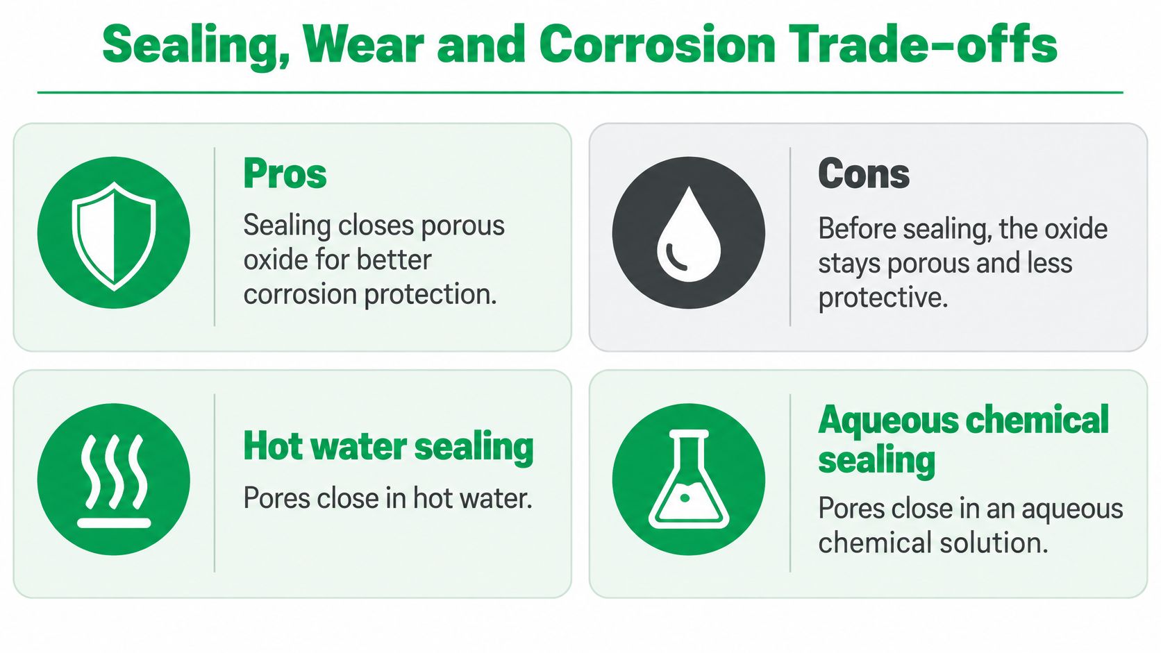
A sealed enclosure that shrugs off fingerprints can still be the wrong call on a sliding bore. Sealing improves corrosion and stain resistance, and on hardcoat it can cut abrasion resistance at the same time. Decide which failure mode ends the part's life before you write "seal" on the drawing.
Fresh anodic oxide is porous. The ASTM B580 standard listing generally calls for sealing in water or aqueous chemical solutions unless sealing is explicitly excluded. Sealing hydrates and closes portions of the pore structure, so moisture and corrosive species have fewer paths inward.
On hardcoat, that same closure has a cost. Sealing or dyeing can noticeably reduce abrasion resistance in some hard-coat conditions. Those outcomes sit on different alloys, film thicknesses, and contact pressures, which is why a blanket "seal everything" note is bad engineering.
Let the Dominant Failure Mode Decide
Humidity, salt air, fingerprints, and cleaning usually mark an enclosure long before abrasive wear does. A sealed Type II film is the practical choice there. On a sliding bore or shaft contact, abrasion ends service life first, so an unsealed or specially lubricated Type III hardcoat often keeps hardness longer.
| Application | Finish to request | Sealed? | Acceptance check |
|---|---|---|---|
| Enclosure or consumer housing | Type II, dyed | Yes, sealed | Salt-spray and appearance check |
| Sliding bore, shaft or bushing | Type III hardcoat | Usually unsealed or lubricated | Taber-type abrasion test |
| Electrical contact or ground point | Masked, left bare | Not applicable | Continuity check |
| Architectural facade or window | Architectural Class I or II | Yes, sealed | Corrosion test per spec |
Specify a Test, Not an Adjective
"Corrosion resistant" is not an acceptance criterion. Name a salt-spray test or an acid-based sealing test when corrosion governs. Name Taber-type abrasion testing when wear governs. The shop can then quote the test, run it, and report a pass or fail instead of arguing about intent after parts arrive.
Anodic oxide is electrically insulating. Ground pads, bonding faces, and contact points stay masked, then get a continuity check. I would not approve sealing or dyeing on a wear surface until the required wear, color, and corrosion performance are confirmed against the actual specification.
Color Matching, Masking and Batch Consistency
Dyed Type II gives you the widest palette, including black, gray, bronze, and brighter colors that hardcoat can't realistically hold. Type III stays mostly in dark territory because the thick film itself darkens the part before any dye goes in. Picking a color name, though, is the beginning of the problem rather than the solution.
Color depends on alloy, surface preparation, oxide thickness, dyeing, and sealing, and the Aluminum Anodizers Council reference guide notes that color can vary substantially with alloy and thickness. Change only the sealing method and the shade can shift. Over-sealing may create haze or wash out dye, while under-sealing can impair color durability, so the same dye tank doesn't guarantee the same finished color.
Questions Buyers Skip Until Assembly
Three questions decide whether a multi-part product looks intentional or patched together. Can the prototype color be reproduced in production? Should every visible part use the same aluminum alloy? What lighting and tolerance govern acceptance when two people disagree about a match?
Anodized parts aren't painted over, so there's no opaque topcoat to hide a difference between a 6061 lid and a 7075 base. On an assembled product those two pieces sit side by side under the same light, and a small shift reads immediately. Surface preparation matters just as much, which is why a controlled pre-finish such as bead blasting aluminum before anodizing needs the same direction, media, and coverage on every visible part.
Make Color Measurable
- Master or limit sample: Approve a physical reference part, plus limit samples showing the darkest and lightest acceptable result.
- Fixed inputs: Lock the alloy, temper, pre-finish, film thickness, dye, and seal for all visible mating parts.
- Batch grouping: Anodize adjacent parts in the same batch when the assembly can't tolerate visible drift.
- Defined inspection: Use spectrophotometer readings where appropriate and visual inspection under defined lighting for final acceptance.
- Cosmetic zones: Mark show faces, secondary faces, and hidden faces so the shop doesn't polish or rack a part the wrong way.
A color match guarantee without a measurement method is incomplete. For a one-off prototype, visual similarity may be fine. For production assemblies, define the allowable color difference in the purchase specification.
Masking belongs in this conversation too. Plugs, tape, and liquid mask keep threads, bores, and ground points bare, and racks leave contact points, so draw those areas on the part instead of describing them in an email. At FIRMFG we offer anodizing, powder coating, electroplating, bead blasting, passivation, sandblasting, and decorative finishing services, so the pre-finish and the anodic film can be planned as one sequence instead of being handed between shops.
How to Fit Anodizing Into a CNC Workflow
Anodizing works best when the machinist knows about it before the first cut. If the finish appears only after parts are made to final size, you're choosing between masking, rework, and accepting a fit you didn't design. The sequence below keeps the coating inside the manufacturing plan.
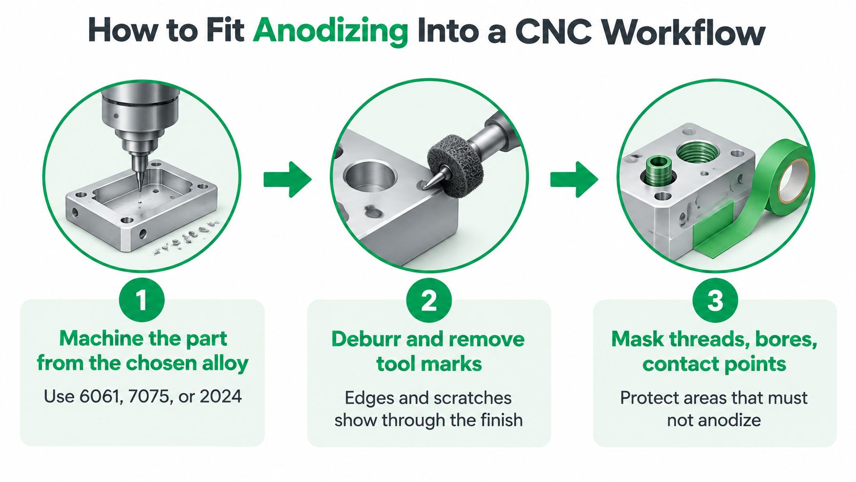
The Working Sequence
- Machine from the chosen alloy: We offer aluminum CNC machining and machine aluminum alloys 6061, 7075, and 2024, and your choice should be settled before finishing because alloy drives color and film response. Switching alloy after approving a color sample restarts the cosmetic approval. Our aluminum CNC machining service is where that material and geometry decision belongs.
- Deburr and remove tool marks: Anodic film follows the surface rather than leveling it, so scratches, sharp burrs, and torn edges show through. Break edges deliberately, because very sharp corners build thin, fragile coating.
- Mask what must stay bare: Protect threads, press-fit bores, sealing faces, and electrical contacts before racking. The common slip is anodizing an unmasked internal thread and then discovering that a standard fastener won't start.
- Anodize to the drawing: Run the type, class, and thickness you specified, with rack contacts placed in approved zones. If the drawing is silent on rack marks, a visible face can become the contact point by default.
- Dye and seal as specified: Keep the order straight. Dye goes into open pores, then sealing closes them, and assembling parts before this is complete can trap residue on mating surfaces.
- Finish-machine if growth requires it: Where the specification permits, cut critical bores or faces after coating to recover exact size. Remember that any surface you machine afterward is bare aluminum again and needs its own corrosion decision.
- Inspect, then assemble: Verify film thickness, appearance, masked areas, thread fit, and continuity at ground points before parts enter assembly. Finding a tight bore at final assembly is the most expensive place to find it.
Where Turnaround and Cost Actually Come From
Price the queue rather than the tank time. A standard clear Type II job in one alloy and one color can ride a supplier's standing rack schedule, so parts move with work that's already planned. A one-off dye lot, a tight hardcoat thickness window, or a separate seal requirement needs its own rack setup and often a second inspection pass.
Masking-heavy parts behave differently again. Plugging twenty holes and taping three faces is hand labor, and on a small lot that labor dominates cost long before acid or electricity does. Batching parts by alloy and color shortens the wait because the shop isn't breaking a rack setup for every variation.
Scheduling rule: Group by alloy first, then by color, then by thickness. Every change inside a batch adds a setup, a rack change, or an inspection exception.
Our process includes design review analyzing CAD files for manufacturability, prototyping, optimization, and production. I would use that design review before cutting metal, because a reviewer can flag a bore with no growth allowance, a thread with no masking note, or mixed alloys on a cosmetic assembly while the fix is still a CAD edit.
Write an Anodizing Spec and Request a Quote
A quotable spec fits in a drawing note and an RFQ email. It doesn't need to be long, but it does need to remove the guesses that let two suppliers price two different finishes. Copy the structure below and fill in your values.
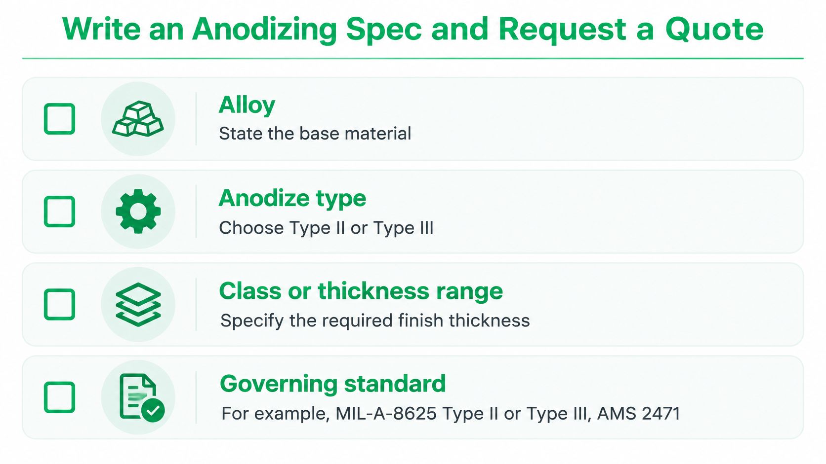
| Spec line | What to write | Why it matters |
|---|---|---|
| Alloy and temper | 6061-T6, 7075-T6, 2024-T3 or the casting alloy | Alloy sets color, hardness and coating response |
| Anodize type and class | Type II 5 to 25 µm; Type III 40 to 60 µm; ASTM B580 hard coat 50 µm minimum | Drives wear life, dimension growth and price |
| Governing standard | MIL-A-8625 Type II or III; AMS 2471 undyed; AMS 2472 dyed; ISO for architectural work | Gives the shop an auditable acceptance basis |
| Color and appearance | Master or limit sample plus the defined lighting condition | A color match cannot be measured without a reference |
| Sealing | Sealed, unsealed or lubricated per the dominant failure mode | Sealing trades wear resistance for corrosion protection |
| Masking | Rack contacts, threads, bores and ground points drawn on the part | Anodic film is insulating and clogs threads |
| Post-finish limits | Bore, thread and fit dimensions after coating | Half the film grows outward into the fit |
| Inspection | Eddy-current thickness, Taber abrasion, salt spray, visual | Turns anodized into a pass or fail |
What to Send With the RFQ
Attach the drawing, the 3D model, quantity, and whether this is a prototype, a pilot build, or repeat production. Say explicitly whether color must match across batches and whether adjacent parts must run together. If you have an approved sample, send it or reference it by revision so the shop isn't matching a photograph.
Then ask three direct questions. How do you hold color between batches? Which thickness measurement method will you report? Can you finish-machine after coating if a fit needs it? The answers tell you more about process control than a capability list does.
Our production manufacturing processes include CNC machining, injection molding, sheet metal, assembly, and finishing, so the coating can be planned against the machined geometry instead of being quoted in isolation. Our NPI services achieve over 99% first pass yield, which matters when a first article has to prove fit, color, and thickness in one build. Send the drawing with the spec lines above completed, request design review with the quote, and approve a first article before you release the full quantity.
Send us your drawing with the alloy, Type II or Type III callout, thickness, sealing choice, and masked areas marked, and we'll review the fits before quoting your anodizing aluminum services and machining as one production flow. Visit FIRMFG to start that design review and request a quote for your next prototype or production run.