Blind Tapped Holes: Design Rules and CNC Best Practices
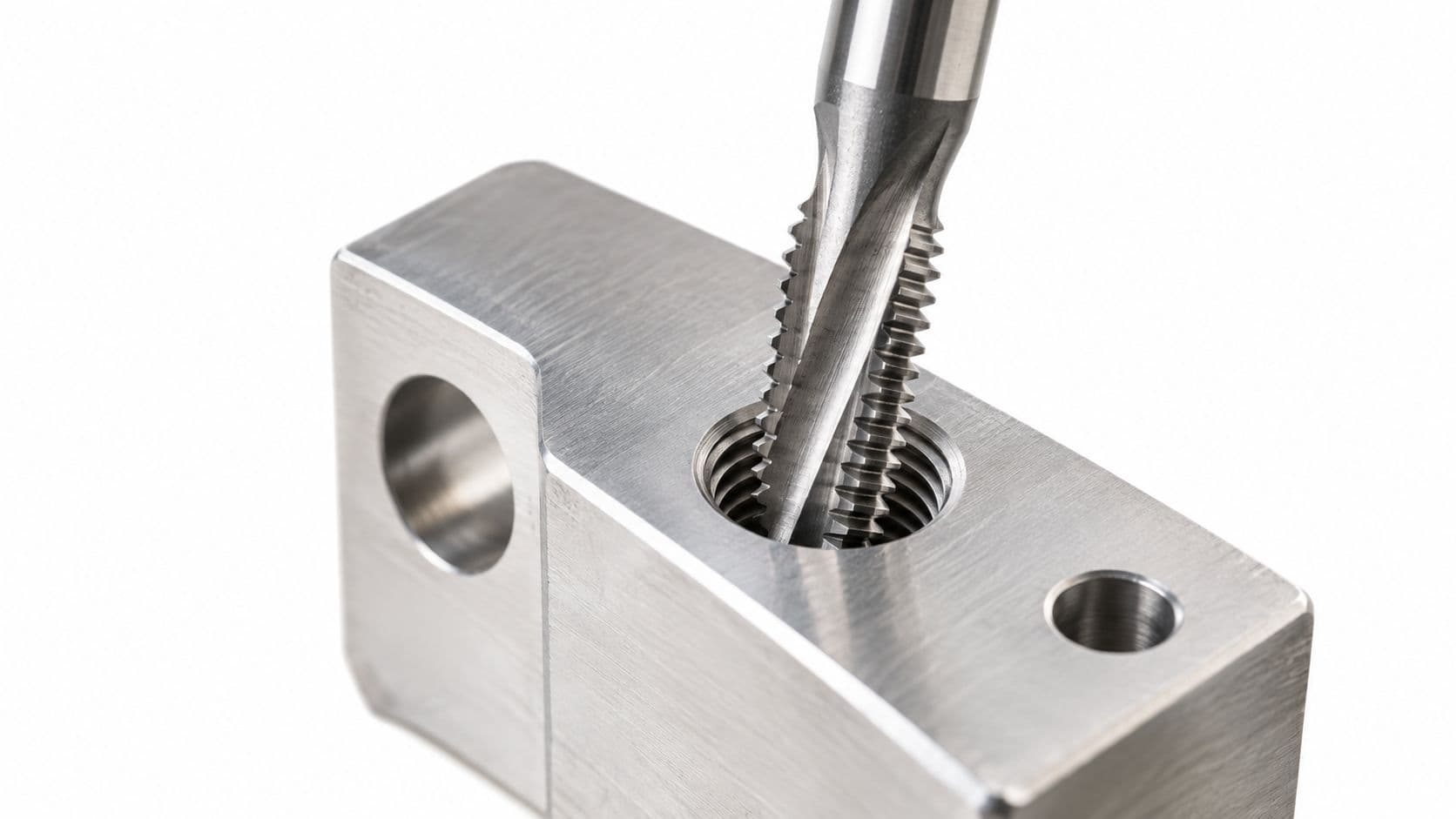
You've specified an M6 thread, 12 mm deep, in a steel bracket. The shop drills to 12 mm, taps the hole, and the fastener appears to fit. After a couple of assembly cycles, the threads strip. Nothing seems obviously wrong. The thread callout was correct, the drill reached the stated depth, and the tap entered the hole.
The problem is that “M6 × 1, 12 deep” doesn't describe one physical dimension. A blind tapped hole has a drill depth, a usable full-thread depth, and clearance below the threads. Treating those as the same number is how an apparently correct drawing produces an unreliable part.
Through holes are forgiving because chips can leave through the opposite side. Blind tapped holes trap chips, concentrate heat, and force the tap to work close to a closed bottom. The design therefore has to account for the tool's lead, incomplete threads, chip space, and the material being cut. The following guidance separates those decisions so your drawing, CNC program, and inspection plan describe the same feature.
Table of Contents
- Why Blind Tapped Holes Deserve Their Own Engineering Conversation
The three decisions hidden in one callout
The Anatomy of a Blind Tapped Hole and What Each Number Means- Read the hole from the surface to the bottom
Thread Engagement Rules That Actually Match the Material- Recommended Thread Engagement by Material Class
Choosing the Right Tapping Method for a Blind Hole- Cut taps
Material-Specific Tapping Challenges and How to Beat Them- Aluminum
Drawing Callouts and DFM Checklist for Blind Tapped Features- Turn the geometry into separate callouts
Inspection and Verification of Finished Blind Tapped Holes- Start with the thread
Why Blind Tapped Holes Deserve Their Own Engineering Conversation
A fastener can start cleanly in a blind tapped hole and still fail later. The hole ends inside the part rather than breaking through the opposite face, so chips remain trapped during tapping. They can collect under the tap flutes, pack at the bottom, and interfere with both cutting and thread formation.
A through hole can still have a poor pilot diameter or a damaged tap, but its depth is less often the main constraint. In a blind hole, the tool must create the required usable thread without bottoming, while leaving room for its lead and the chips it produces. The hole can be drilled to the nominal thread depth and still contain less usable thread than the design requires.
Practical rule: Treat drill depth, usable thread depth, and bottom clearance as separate dimensions.
The three decisions hidden in one callout
Suppose a drawing specifies M6 × 1 with 12 mm thread depth. The callout identifies the thread form and required usable engagement, but it does not by itself define the drill travel. The drill creates a conical bottom, while the tap's chamfer or lead produces incomplete threads near the entry and lower runout.
A commonly cited manufacturing rule allows the drill to extend beyond the usable thread depth by about 2 to 3 thread pitches. Other guidance recommends 3 to 5 pitches to reduce bottoming and provide chip space, as described in this blind-hole machining guide. For an M6 × 1 thread, the pitch is 1 mm, so the allowance represents actual space in the part, not an extra number added only for drafting.
Read the callout as three physical decisions:
- Drill depth: How far the pilot drill reaches, including the drill-point geometry.
- Usable thread depth: How much full, functional thread the fastener can engage.
- Bottom clearance: The relief below the usable thread where the tap can finish and chips can collect.
That separation also clarifies repair planning. A stripped aluminum feature may accept an insert or other rework. A damaged blind hole in difficult stainless or titanium can be much harder to recover because access, chip removal, and tool loading are less forgiving. Blind tapped holes therefore belong in DFM review, CNC planning, and inspection planning, not only in the fastener callout.
The Anatomy of a Blind Tapped Hole and What Each Number Means
Suppose a drawing calls for M6 × 1 with 12 mm thread depth. At the machine, that note becomes three separate physical decisions. The fastener needs 12 mm of usable thread, the drill must travel farther, and the tap needs clearance before it reaches the conical drill point.
Start at the part surface. The entry chamfer guides the fastener into the thread and removes a sharp edge that could be damaged during assembly. It is not full engagement. The tap's lower runout also contains incomplete threads, so it cannot be counted as usable thread.
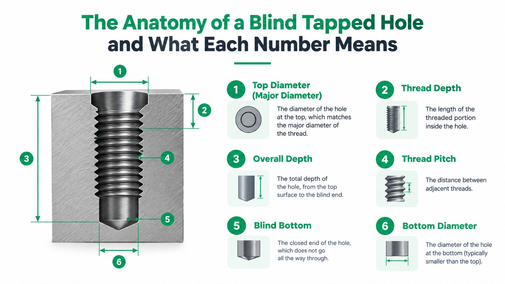
Read the hole from the surface to the bottom
Drill depth runs from the part surface to the end of the drilled cavity. A conventional twist drill leaves a conical point, not a flat bottom. That geometry consumes part of the axial depth, so the drilled hole is not a cylindrical pocket with the same depth at every location. Shop practice often allows roughly 0.29 times the drill diameter for the drill point.
Usable thread depth is the length of full thread that can carry fastener load. It is shorter than the total tapped region because the tap enters progressively, and its lower portion ends in incomplete thread forms or runout.
Bottom clearance is the space below the last usable thread and above the drill point. It gives chips room to collect and keeps the tap chamfer from being driven into the bottom. The space does not strengthen the joint, but it protects the process from bottoming.
Read the feature as four stacked zones:
- Entry chamfer, where the fastener begins engagement.
- Full threads, the functional engagement length.
- Tap runout, where the thread form is incomplete.
- Clearance pocket and drill point, where chips collect and the tap must stop.
Why the drawing must separate them
Drafting guidance may show thread depth and drill depth as separate requirements, such as M6 × 1, 12 DEEP / DRILL 5.0 × 17 DEEP, as described in this CNC blind-hole overview. The values depend on the joint, tool, material, and machining method, but the notation makes the design logic clear: thread specification and hole depth are independent design variables.
A drill-depth-only callout can meet its numeric target while leaving too little full thread. A usable-thread-only callout leaves the machinist to establish drilling depth around lead, runout, drill point, tool wear, and chip space. Separating the three decisions gives manufacturing and inspection teams something they can verify.
Thread Engagement Rules That Actually Match the Material
Thread engagement is a joint-strength decision first and a machining decision second. A widely used starting point for general metal applications is engagement around 1.0 to 1.5 times the nominal bolt diameter, with at least 0.5 times the major diameter of additional unthreaded depth for chip clearance, according to these tapped-part design guidelines.
That rule doesn't replace an engineering check. The bolt grade, joint load, parent material, wall thickness, and repeated assembly all influence the required engagement. A soft material may need more length to distribute load, while a strong material may reach the joint's useful capacity before a very deep thread adds value.
Recommended Thread Engagement by Material Class
| Material | Minimum Engagement | Typical Engagement | Notes |
|---|---|---|---|
| Aluminum | Use the lower end of the general engagement range only after checking load and thread shear | Around the general range, with added length when the joint is highly loaded | Softer material can require more engaged thread to prevent stripping |
| Mild steel | Often suitable within the general metal range | Select from the joint load and wall geometry | Chip control is usually more manageable than in a blind stainless hole |
| Stainless steel | Avoid treating the minimum as automatic | Allow additional engagement when work hardening and assembly load demand it | Tapping heat and torque can govern the process |
| Titanium | Validate both engagement and machining strategy | Conservative engagement with generous process relief | Heat retention and chip packing make bottom clearance important |
Designers often repeat a simple material formula, but the rule bends at the edges. Thin walls can distort or split before the threads develop their theoretical capacity. Soft cast materials may behave differently from wrought stock. Annealed and hardened conditions can change cutting behavior, torque, and the likelihood of thread damage.
More thread isn't automatically more reliable. Once the joint has enough engagement, extra depth can increase cycle time, friction, and tapping difficulty without improving the connection.
For a specific metric thread, confirm the tap drill and thread form with the supplier rather than assuming the nominal diameter describes the pilot hole. A useful example of the separate tap-sizing decision appears in this 10-32 drill and tap size guide. The drawing should still identify the required usable thread depth and the drilling allowance independently.
Choosing the Right Tapping Method for a Blind Hole
The tapping method changes the geometry you need below the usable thread. A cut tap removes material and produces chips, a forming tap displaces material without producing conventional chips, and a thread mill removes the thread with a rotating cutter that can be retracted from the hole.
| Method | Best Material Fit | Bottom Clearance Needed | Chip Risk in Blind Hole | Tool Cost |
|---|---|---|---|---|
| Conventional cut tap | Broad range, including many steels and difficult alloys | Relief must accommodate lead, runout, and chips | High if chips pack at the bottom | Usually lower |
| Thread-forming tap | Ductile aluminum and other formable materials | Generous clearance is needed because displaced material occupies space | Lower loose-chip risk, but forming pressure is higher | Moderate |
| Thread milling | Deep, chip-prone, or high-value features where control matters | Clearance must allow the cutter to enter, interpolate, and retract safely | Lower risk of a long chip nest, though milling still creates chips | Usually higher |
Cut taps
Cut taps remain a practical default for many short runs and for materials that don't form threads reliably. Spiral-flute versions can pull chips upward from a blind hole, while bottoming-style geometry can place useful threads closer to the bottom. The tradeoff is unforgiving: if the hole is too shallow, the tap lead or packed chips can push the tool into the drill point.
Forming taps
Forming taps suit ductile materials because they displace material instead of cutting a conventional chip. That doesn't make bottom clearance optional. The displaced material needs room, and the forming load can rise sharply if the pilot hole is undersized. Use this method only when the material and tap manufacturer support it, and verify the pilot diameter carefully.
Thread milling
Thread milling becomes attractive when a broken tap would be expensive, when the material is prone to chip welding, or when the hole is deep enough that chip evacuation dominates the risk. The cutter removes less material per revolution than a tap but gives the machine a controlled path and a way to retract from the feature. It also requires accurate pre-machining, stable tool holding, and enough room for the milling approach.
Material-Specific Tapping Challenges and How to Beat Them
The same blind-hole program can behave very differently in aluminum, steel, stainless, titanium, and plastic. Choose the tool and chip strategy around the material's failure mode, not around a generic coolant instruction.
Aluminum
Aluminum can produce gummy chips that weld to the tap flutes and lock the tool in the hole. A sharp, steep-flute tap, effective coolant delivery, and a drilling cycle that clears chips before tapping can reduce that risk. The FIRMFG aluminum CNC machining guidance is a useful reference when the same component includes deep pockets or multiple threaded features.
Don't assume that aluminum's low cutting resistance makes it safe to rush. A packed chip can generate more torque than the material itself would suggest, especially near the bottom of a blind cavity.
Mild steel
Mild steel is often easier to manage, but a poor drilling operation can still create trouble. If the drill rubs, loses its edge, or re-enters the hole after work hardening the surface, the tap may encounter a much tougher band than expected.
A clean entry, a properly sized pilot, and a coating selected for the tool and steel grade help maintain consistent torque. Watch the first production pieces for burrs and torn threads instead of relying only on whether the tap completes its cycle.
Stainless steel and titanium
These materials retain heat and can harden or damage the tool edge when it dwells at the bottom. Rigid tapping, controlled spindle speed, strong coolant delivery, and a programmed reversal without hesitation are more useful than adding cutting fluid after the problem appears.
For deep blind features, provide coolant access and enough bottom relief for the chosen tap. If torque rises during the cycle, stop and investigate pilot diameter, tool wear, chip packing, and material condition before increasing the depth.
Plastics
Plastics can strip from excessive assembly torque, soften from heat, or smear when the tool rubs. A forming tap may work in a suitable ductile plastic, but the pilot size and material behavior must be validated. Interrupted cutting, air or mist for chip removal, and controlled tapping speed can help prevent heat from turning a clean thread into a distorted one.
Drawing Callouts and DFM Checklist for Blind Tapped Features
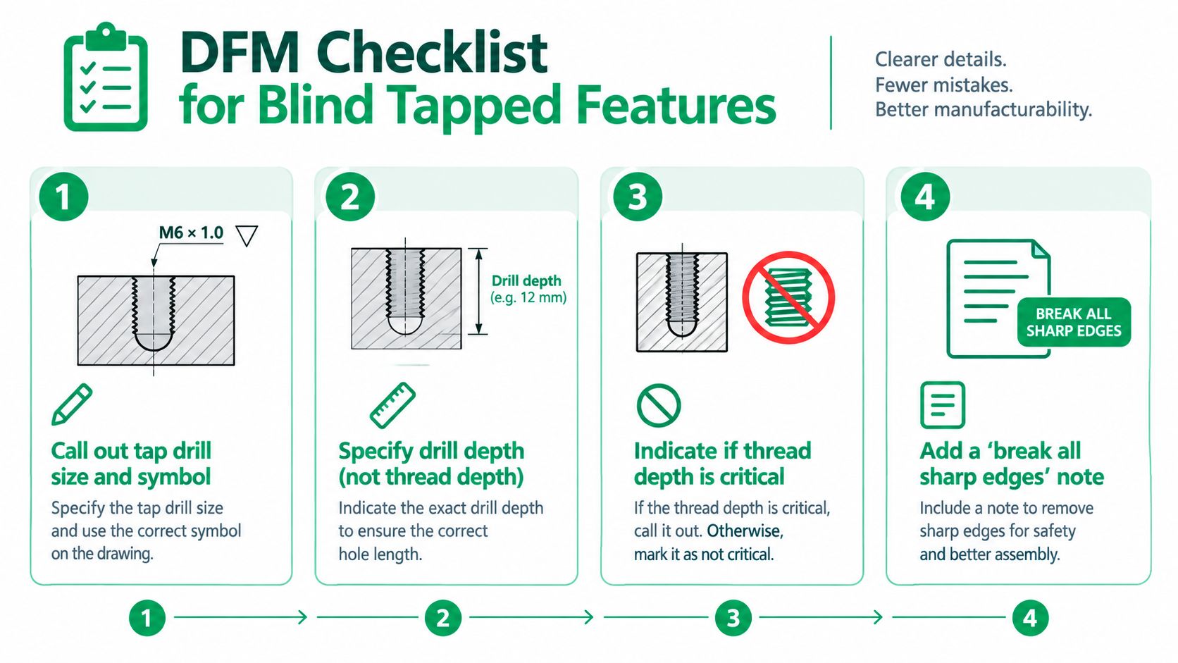
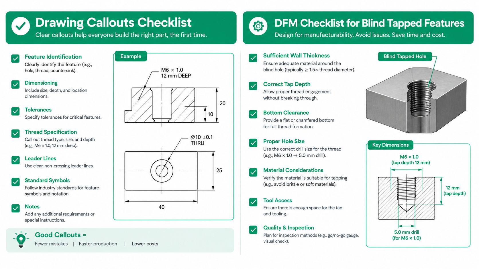
A supplier should be able to read the drawing and answer three questions without guessing. What diameter is drilled, how deep does the drill go, and how much of the resulting thread must be functional?
Turn the geometry into separate callouts
A clear drawing identifies the thread using the applicable metric or unified thread notation, then gives the usable thread depth separately from the drill depth. It should also identify the tap-drill diameter when that diameter is critical to fit, strength, or process control.
The entry treatment belongs in its own decision. Specify a chamfer, countersink, or edge break when the fastener needs a clean start or when burrs could interfere with seating. Don't let the entry chamfer get counted as full thread unless the joint calculation explicitly allows it.
For the bottom, state the required clearance style or drill condition when the feature is sensitive. A standard drilled point may be acceptable for a general fastener, while a flat-bottom operation may be necessary when the fastener must approach the bottom or when the remaining material has a specific seating function.
DFM questions to answer before release
Use the following checklist with the 3D model and drawing:
- Joint requirement: What load, bolt grade, and assembly frequency determine the usable engagement?
- Material condition: Is the stock aluminum, steel, stainless, titanium, plastic, annealed, cast, or hardened?
- Wall geometry: Is there enough material around the hole to prevent distortion, breakout, or interaction with a neighboring feature?
- Edge distance: Could the tap weaken a nearby edge or open into a pocket?
- Process access: Can the machine hold the part rigidly and deliver coolant to the hole?
- Tapping method: Is the supplier expected to use a cut tap, forming tap, or thread mill?
- Inspection method: Will a plug gauge, depth tool, mating fastener, probe, or another method verify the requirement?
- Critical dimensions: Which depth is functionally critical, and which dimension is only a machining allowance?
A useful supplier note can say, in plain language, that the thread depth is the required full-thread engagement and the drill depth is a separate manufacturing dimension. That sentence prevents a common tolerance-stack failure before it reaches the machine.
Inspection and Verification of Finished Blind Tapped Holes
A finished blind tapped hole needs more than a fastener that happens to start. Verify the thread, the drilled depth, and the condition at the bottom, because each check answers a different question.
Start with the thread
A GO plug gauge checks whether the usable thread accepts the expected form. A NO-GO gauge helps identify whether the thread is too loose, but in a blind hole the inspector must also confirm that the gauge reaches the intended usable depth rather than stopping in the entry chamfer or incomplete runout.
A mating fastener can reveal problems that a gauge doesn't show during repeated assembly. If the screw starts cleanly but bottoms early, the issue may be inadequate bottom clearance or a fastener that is longer than the functional cavity. If it strips at the specified assembly torque, inspect the pilot diameter, material condition, thread engagement, and evidence of torn or incomplete threads.
Verify depth and bottom condition
Measure drilled depth against the drawing's drill-depth requirement, not against the thread-depth requirement. Visual inspection should look for chip nests, burrs at the chamfer, crushed first threads, and packed debris at the bottom. A probe or coordinate measuring machine can help verify location and depth when the feature is difficult to access. For more involved dimensional verification, CMM inspection services can provide a controlled measurement route.
Keep a record of tap breakage, unusual torque, and tool changes. Those events can identify a process drift before a batch of parts reaches assembly.
| Observed Symptom | Likely Root Cause | Corrective Action |
|---|---|---|
| Fastener won't start | Missing chamfer, burr, incorrect pilot diameter, or damaged entry thread | Deburr and inspect the entry, verify the tap drill, and check the first threads |
| Fastener bottoms out early | Drill depth too shallow, insufficient bottom clearance, or fastener too long | Separate the thread and drill-depth requirements, then confirm the mating fastener length |
| Fastener strips at torque | Insufficient usable engagement, oversized pilot, damaged threads, or weak parent material | Review joint load, inspect the pilot and thread form, and validate material-specific engagement |
| Tap breaks near the bottom | Chip packing, inadequate relief, tool wear, or bottoming | Increase process clearance where design permits, improve chip evacuation, and replace worn tooling |
| Gauge passes but assembly fails | Gauge depth or fastener seating doesn't represent the real joint | Use a mating-fastener test alongside gauge and depth verification |
Inspection frequency should follow the feature's risk and production plan. First articles and safety-critical threads warrant complete verification, while repeat production can use a documented sampling plan appropriate to the part and quality system. The key is consistency. Everyone must agree whether “depth” means drill depth, full thread, or total tapped cavity.
FIRMFG can review blind tapped-hole drawings, recommend machining approaches for metal and plastic parts, and verify difficult features through documented inspection processes. Share your model and drawing with FIRMFG to get DFM feedback and a manufacturing route matched to your thread depth, material, and production needs.