10-32 Drill Tap Size Reference Guide with Sizing Tables
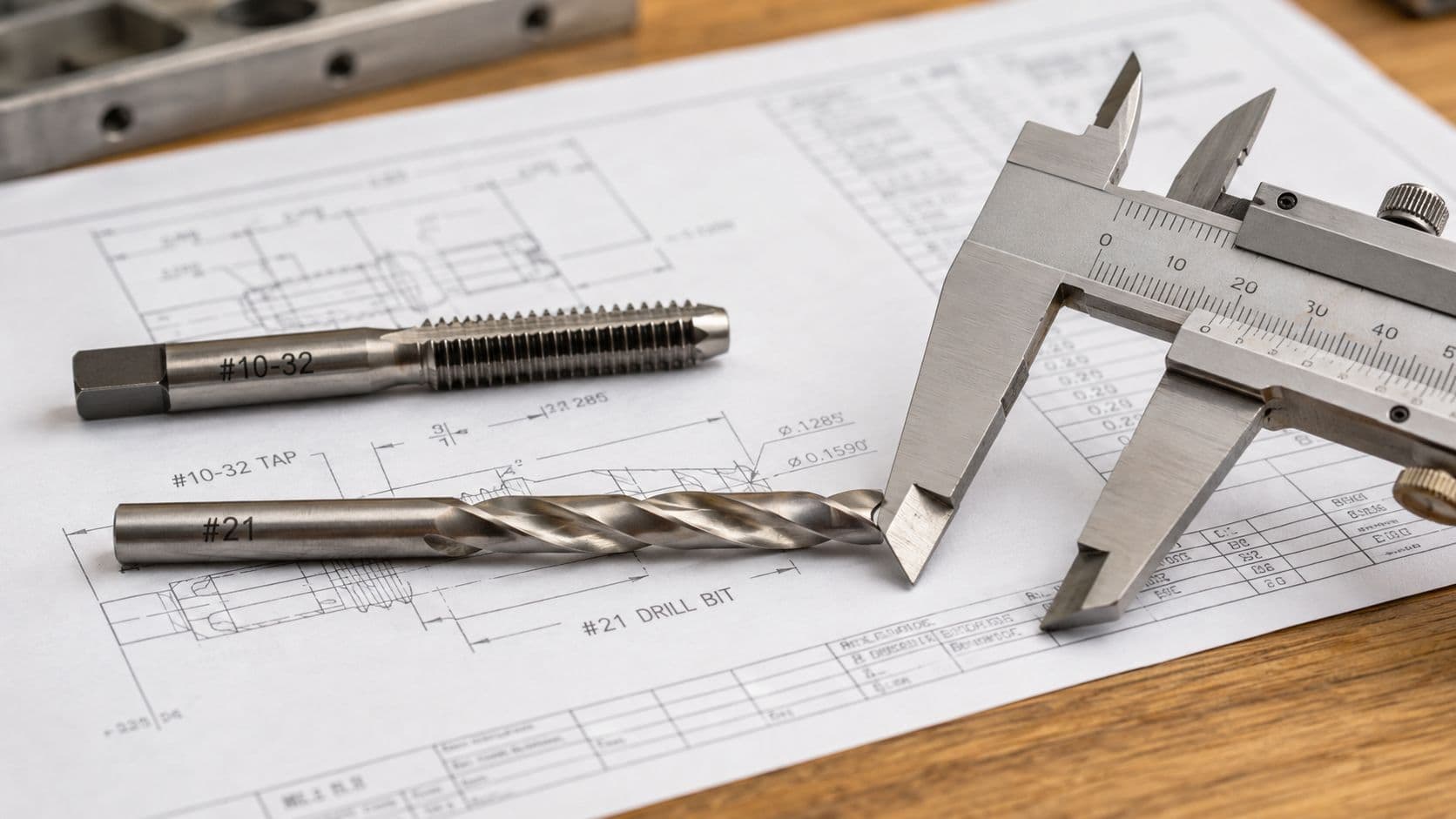
Use a #21 drill bit, 0.1590 in or 4.04 mm, to tap a 10-32 UNF thread. That's the standard starting point, but the right hole still changes with material, chip control, and how much thread engagement you need.
You're usually staring at a part on the bench when this question comes up. The drawing says 10-32, the drill index has three nearby sizes, and one hole needs to accept a screw while another needs to be tapped cleanly. Mixing those jobs is where good parts get scrapped.
Table of Contents
Understanding the 10-32 UNF Designation- Fine thread, not coarse thread
Tap Drill vs Clearance Drill vs Thread Engagement Drill- Three separate hole decisions
Tap Drill Sizes and Decimal Equivalents for 10-32- How the engagement numbers line up
Clearance Hole Sizes for 10-32 Screws- Which clearance size belongs where
Blind Holes vs Through Holes for 10-32- What keeps blind holes from failing
Tapping Speeds Lubrication and Tool Selection- Starting points by material
Common Pitfalls When Drilling and Tapping 10-32- The failure modes to watch for
DFM and Prototyping Tips for 10-32 Features- How to make the drawing easier to build
Quick Reference Card for 10-32 Sizing
What Drill Bit to Use for 10-32 Threads
For a standard 10-32 UNF internal thread, the right tap drill is #21, which is 0.1590 in or about 4.04 mm (tap drill chart reference, 10-32 UNF drill table). That's the default answer a machinist reaches for first, and it's the one to use unless the job calls for a different thread engagement target.
Why the answer changes in real work
The drill size isn't just about making a hole that “fits.” It controls how much material the tap has left to cut, which changes torque, chip load, and final thread strength. For that reason, a tap drill that works well in aluminum can feel too aggressive in a hard alloy, while a larger drill can save a tap in a stubborn material if the design can accept slightly less thread depth.
The other trap is confusing the hole type. A tap drill is for cutting threads. A clearance drill is for letting the screw pass through without biting, and a thread-engagement drill is chosen when the engineer is aiming at a specific percentage of thread depth rather than accepting the standard callout.
Practical rule: if the drawing says 10-32 tapped hole, start at #21. If the drawing says 10-32 clearance, stop and check the clearance chart instead of grabbing the same bit.
The rest of this guide breaks that difference into usable shop-floor decisions. Once you separate tapping, clearance, and engagement, the sizing stops feeling arbitrary and starts looking like a set of lookup columns.
Understanding the 10-32 UNF Designation

A 10-32 callout gives you two lookup fields at once. 10 is the nominal screw size, with a major diameter of 0.1900 in. 32 is the thread density, meaning 32 threads per inch, which works out to a pitch of 0.03125 in (Unified thread reference).
Fine thread, not coarse thread
That pitch is what separates 10-32 from the coarse family member, 10-24. The 24 TPI version leaves more room between threads and behaves differently in assembly, while 10-32 gives the finer spacing that machinists reach for when they want tighter thread engagement and a more controlled tapped joint. In the shop, that usually shows up on machine-screw work where fit and repeatability matter more than fast assembly.
The two sizes share the same nominal screw family, but they do not call for the same hole strategy. A junior machinist who reads 10-32 as “small screw” and stops there is already mixing up thread form with hole size.
Unified thread sizing has a long standard history behind it, and that history matters because the designation is not just a label, it is a shared language across drawings and gauges. The history of the Unified National Thread standard is documented in older gauge references and standard notes, which is why the same 10-32 callout still means the same thing on a print when the spec is read correctly.
By the time you reach the drill chart, the designation has already told you the fastener family, the thread density, and the kind of joint the designer had in mind. That is the first filter, before anyone starts comparing tap drill, clearance drill, thread-engagement drill, or decimal and metric equivalents.
Tap Drill vs Clearance Drill vs Thread Engagement Drill
A lot of mistakes start because people treat every 10-32 hole as the same hole. It isn't. The tap drill, the clearance drill, and the engagement-based drill all serve different jobs, and the drill diameter changes with the job.
Three separate hole decisions
| Hole Purpose | Recommended Drill | Decimal Diameter | Typical Use |
|---|---|---|---|
| Tap hole | #21 | 0.1590 in | Cutting 10-32 internal threads |
| Close-fit clearance hole | #9 | 0.1960 in | Precise assembly, better location control |
| Free-fit clearance hole | #7 | 0.2010 in | Panels, service covers, easier pass-through |
The tap-drill number is the one that creates thread form. The clearance-hole numbers are larger because the screw body has to pass through the part without cutting or binding (clearance hole distinction). If you use #21 for clearance, the screw won't seat correctly because the hole is meant to be threaded, not passed through. If you use #7 to tap a hole, the tap has too little material to bite into and the thread will be weak.
What the engineering intent really is
The engagement-based drill sits between those two decisions. Instead of asking, “What bit goes with 10-32?” ask, “How much thread engagement does this part need?” That question matters in thin stock, soft metals, and parts where torque on the tap is already high. It also matters when the hole is blind, because chip room gets tight fast.
A shop can only cut a good 10-32 thread if the person calling the hole knows whether the screw needs to thread, pass through, or seat against a tolerance stack.
Tap Drill Sizes and Decimal Equivalents for 10-32

A 10-32 hole callout is easy to misread if the shop mixes up tap drill, clearance drill, and thread-engagement drill. For the tap column, the standard starting point is #21, and the decimal equivalent is commonly listed as 0.1590 in, or about 4.04 mm. That is the drill most charts use for the ordinary tap-drill case, while the engagement column is where the diameter shifts depending on how much thread you want to cut. Some references also round that size in shop shorthand to about 5/32 in, but the actual decimal is the number to watch (tap chart reference, 10-32 UNF reference).
How the engagement numbers line up
The engagement column is a separate lookup from the tap-drill column. For 10-32, published charts place the drill around 0.1697 in for 50% engagement, 0.1596 in for 75% engagement, and 0.1575 in for 80% engagement (thread engagement chart). That is the practical spread a machinist sees when comparing charts side by side. One source gives #21 = 0.1590 in, another puts the 75% figure at 0.1588 in, and another lists 0.1596 in for 75%. The disagreement sits in the last decimal places, not in the thread designation itself. For a closer look at why those decimals shift, see the analysis of decimal variations in tap drill charts.
Shop takeaway: call out the engagement target when it matters. The decimal can vary a little by rounding and chart method, but #21 is still the tap-drill size most people expect for standard 10-32 work.
Use #21 for routine machine work. If the material is hard, the tap is small, or the part is sensitive to tap torque, choose the engagement target first and let the decimal follow from that. That keeps the callout tied to the job instead of to whichever chart happens to be on the wall.
Clearance Hole Sizes for 10-32 Screws
A clearance hole is a fit callout, not a thread-forming callout. For 10-32, the usual close-fit clearance hole is #9, or 0.1960 in, and the freer clearance option is #7, or 0.2010 in. In metric terms, that puts the holes at about 4.98 mm and 5.11 mm. Clearance-hole tables from hardware suppliers and drill charts agree on the same basic sizes, even if the last decimal can shift from one reference to another.
Which clearance size belongs where
Use close-fit when the screw has to pass through a controlled assembly, especially if another feature is already locating the part. Use free-fit when the screw only needs to pass through cleanly, such as on service covers or sheet-metal panels where a little extra room helps assembly. The larger hole reduces rubbing and hang-up, and it is easier to install in the field.
Keep the clearance chart separate from the tap-drill chart. Clearance sizing follows the screw's major diameter and the assembly tolerance, not the amount of thread you expect to cut. That distinction gets missed on the floor when a #21 tap drill is pulled for a through-hole by habit.
| Clearance Fit | Drill | Decimal Diameter | Typical Use |
|---|---|---|---|
| Close fit | #9 | 0.1960 in | Precision assemblies, locating features |
| Free fit | #7 | 0.2010 in | Panels, covers, service access |
A reputable hardware reference keeps the same split between close and free fit for 10-32 clearance sizing, and the 10-32 clearance chart is the right column to check for that callout. If the screw has to slide through without binding, the hole needs to be larger than the thread-form drill by a clear margin. That is why the clearance drill belongs on a different lookup line from the tap drill, thread-engagement drill, and decimal-equivalent columns.
Blind Holes vs Through Holes for 10-32

Blind-hole tapping is where many 10-32 jobs go wrong, because chip room disappears fast. The practical depth target is usable thread length plus chamfer allowance plus runout, and many shops size the tap depth at roughly 2× to 2.5× the nominal major diameter for safety. With 0.190 in as the nominal major diameter, that puts the working engagement target around 0.38 in at the low end and up to 0.50 in in harder materials, depending on what the part can tolerate.
What keeps blind holes from failing
Chip evacuation is the main problem. A blind hole packs chips against the tap, torque rises, and the tap starts to bind before the thread is finished. Pecking or chip-break tapping helps clear the cut, and bottoming taps only make sense when the geometry needs threads close to the bottom of the hole.
A chamfered drill start also helps keep the tap from grabbing too hard at entry. That matters more in blind holes than through-holes because the tap has nowhere to dump chips once the flute fills.
Through holes are simpler, but not automatic
Through-hole tapping is more forgiving because the cutter can break through the part and clear chips beyond the exit. Even then, drill past the part thickness, leave enough allowance for tap runout, and avoid forcing the tap as it exits. A clean pass-through is still better than a split thread at the far side.
If you only remember one thing about blind holes, remember this, chip space is part of the hole design.
Tapping Speeds Lubrication and Tool Selection
A 10-32 hole can be sized perfectly and still fail if the tap choice and cutting conditions are wrong. Start with the material, then choose speed, lubricant, and tap geometry to match the chip behavior.
Starting points by material
For aluminum, a starting range around 20 to 35 SFM is a practical baseline for tapping 10-32 ([material tapping guidance in the research brief]). For mild steel, start around 15 to 25 SFM. For stainless, stay slower, around 8 to 15 SFM. Those ranges are starting points, not targets carved in stone, because toolholding, hole depth, and lubricity all matter.
Tap geometry and lubrication
Use a spiral point tap for through-holes, a spiral flute tap for blind holes, and a bottoming tap only when the geometry demands thread depth near the bottom of a blind cavity. In steel, a general tapping fluid or 1:1 cutting oil is the usual starting point. Stainless wants a heavier sulfurized or synthetic oil. Aluminum does better with wax-based lubricant or a light cutting fluid.
The fastest warning sign is sound. A squeal usually means the tap is starting to bind, and that's the point where breaking the chip or backing out is smarter than pushing harder.
Practical rule: if the tap stops cutting cleanly and starts singing, the setup is already late.
Match the tool to the hole style and the material, and 10-32 becomes routine instead of risky. That's especially true on small fasteners, where the margin between a clean thread and a broken tap is thin.
Common Pitfalls When Drilling and Tapping 10-32
The same mistakes keep showing up because people assume the drill number alone tells the whole story. It doesn't. A wrong hole purpose, a wrong engagement target, or a bad tap choice can all wreck a 10-32 feature even when the diameter looked reasonable on paper.

The failure modes to watch for
- Using #21 as a clearance hole: the screw binds or won't seat because the hole was sized to cut threads, not pass the fastener. The fix is simple, move to #9 for close fit or #7 for free fit.
- Using #7 as a tap drill: the tap has too little material to cut cleanly, so thread strength falls and the screw feels loose.
- Choosing an aggressive engagement in a hard material: torque climbs and the tap becomes more likely to jam. The fix is to lower the engagement target and match the lubricant to the material.
- Making a blind hole too shallow: chips pack at the bottom, the tap binds, and the part gets scrapped.
- Forcing a bottoming tap too early: the tap can wedge in soft material before the thread path is stable.
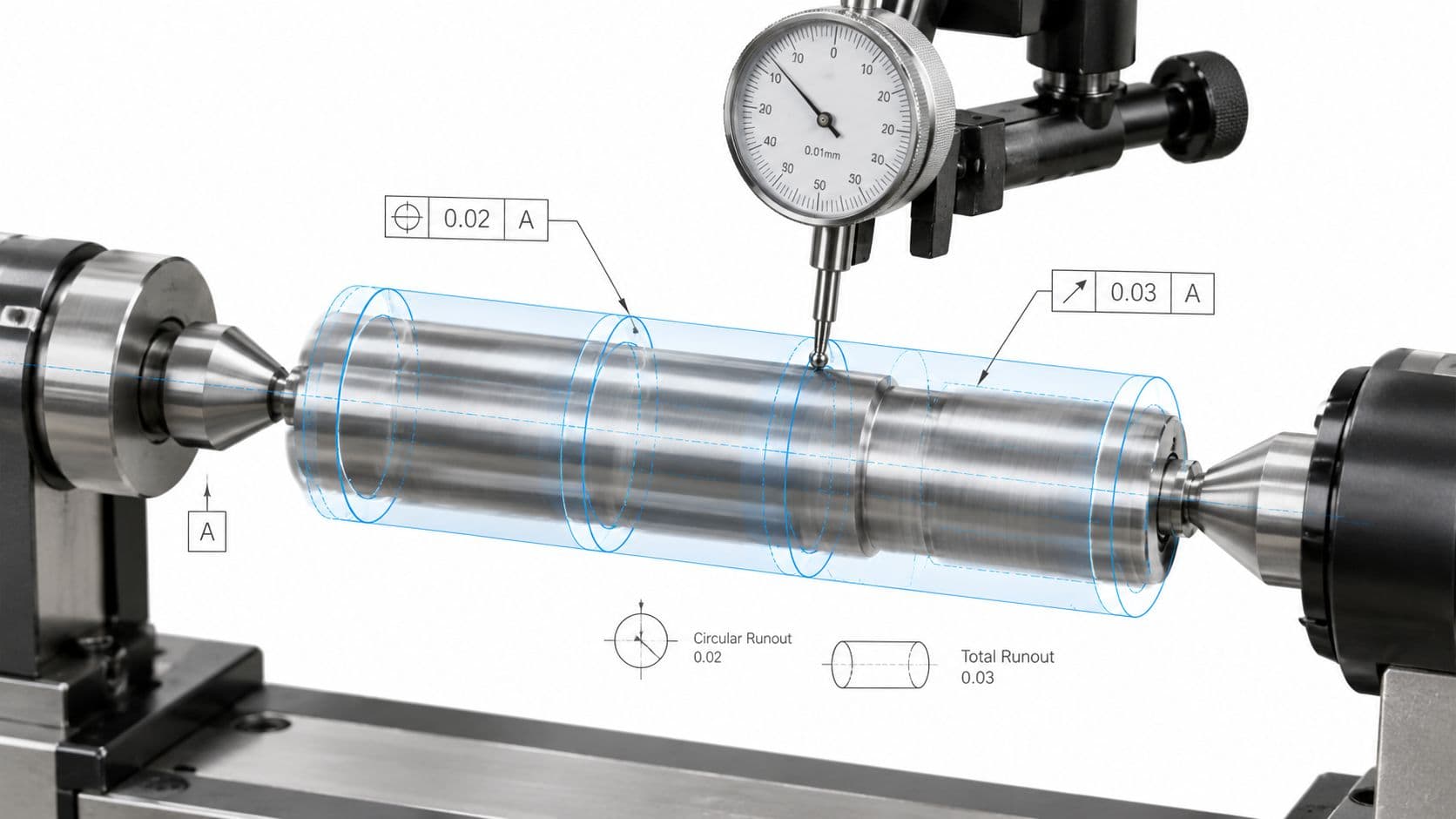
The difference between good and bad here is usually one decision, not five. If the hole is meant to thread, clear the chips and size the tap drill. If the hole is meant to pass a screw, stop trying to thread it. The internal reference on dimensional control is worth keeping nearby, especially when the job has stacking tolerances, and the machining side of that discussion pairs well with FIRMFG's tolerance guide.
DFM and Prototyping Tips for 10-32 Features
The best 10-32 callout is the one the shop can't misread. Put the thread size, depth, and any engagement target on the drawing so nobody has to guess whether the hole is tapped, clearance, or partial-depth. If the fit can tolerate it, leaving 0.020 to 0.030 in of clearance on the tap drill gives a little process room without turning the thread into a sloppy fit.
How to make the drawing easier to build
A chamfer or spotface at the entry helps the fastener seat cleanly and gives the tap a more predictable start. That matters on prototypes, where the first part often gets handled more than the final part. It also matters on production parts, because the first few parts usually expose every ambiguity in the print.
Soft aluminum usually lives comfortably at lower engagement targets, often in the 50% to 60% range, while stainless and tool steel are better candidates for 70% to 75% engagement with coated taps and rigid toolholding. That split is less about one being “better” and more about keeping torque and chip load in a range the setup can survive.
If the program is moving fast, the smartest move is often to hand the feature off to a partner that can drill, tap, and inspect in one workflow. That's where FIRMFG's design-for-manufacturability guidance becomes relevant, especially for low-volume and bridge-production parts that need thread consistency without a long supplier chain.
Quick Reference Card for 10-32 Sizing
Keep this block close to the machine or drop it into your notebook. It separates the choices that usually get confused and gives the first-size answer for each one.
- Thread designation: 10-32 UNF
- Nominal major diameter: 0.1900 in
- Threads per inch: 32 TPI
- Pitch: 0.03125 in
- Default tap drill: #21
- Tap drill decimal: 0.1590 in
- Tap drill metric: 4.04 mm
- Tap drill shorthand: about 5/32 in
- Alternative engagement sizes: about 0.1697 in for 50%, 0.1596 in for 75%, 0.1575 in for 80%
- Close-fit clearance hole: #9, 0.1960 in
- Free-fit clearance hole: #7, 0.2010 in
- Blind-hole depth target: about 2× to 2.5× nominal major diameter when planning for safe engagement
- Speed starting points: 20 to 35 SFM for aluminum, 15 to 25 SFM for mild steel, 8 to 15 SFM for stainless
- Tap style: spiral point for through-holes, spiral flute for blind holes, bottoming tap only when the cavity demands it
For drawing checks, thread verification, and first-article confirmation, it helps to pair the feature callout with inspection instead of leaving it to a quick visual pass. If the geometry is critical, a metrology-backed review like FIRMFG's CMM inspection services keeps the tapped feature honest before the lot moves forward.
If you want a tapped 10-32 feature, a clearance hole, or a prototype run built without guesswork, talk to FIRMFG. They can help turn the drawing into a machinable part, catch the fit issues early, and keep your next build moving with less back-and-forth.