Precision Machine Design: A Practical Engineering Guide
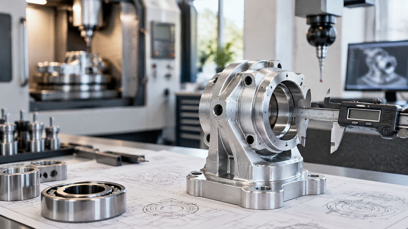
A prototype can look flawless in CAD and still fail dimensional inspection after machining. The bearing seat is slightly out, a mounting face no longer sits square, or a feature shifts after the machine warms up. The drawing may be precise, the machine may be capable, and the operator may be experienced. Yet the finished part still misses its functional requirement.
That gap is where precision machine design earns its keep. The answer isn't automatically a more expensive machine or tighter tolerances across the drawing. It's a design and manufacturing plan that accounts for how geometry, materials, machining, heat, fixturing, and measurement interact, then verifies the features that matter with a suitable inspection method.
Table of Contents
- Why Precision Machine Design Matters
- Core Principles of Precision Machine Design
Control heat and structural movement
Design for stiffness and dynamics together
Matching Design Choices to Manufacturing Processes- Choose the process around the critical features
DFM Checklists and Tolerance Selection- A drawing and process review
Inspection and Quality Control Practices- Build verification into the process
Application Examples Across Industries- Make the requirement fit the application
Designing for Real Process Capability
Frequently Asked Questions- What's a realistic tolerance for CNC machining?
- Should I use CNC or injection molding for a low-volume run?
- What's the difference between a functional datum and a cosmetic surface?
- How do I verify a part meets its tolerance?
Why Precision Machine Design Matters
A failed inspection often exposes a mismatch between design intent and the actual process. A feature may be dimensioned tightly because it appears important in CAD, while the actual assembly depends more on its relationship to a datum, the finish of a mating face, or the position of a hole pattern. When teams don't identify that distinction early, they can spend time and money holding a tolerance that doesn't improve function, while overlooking a more consequential source of error.
Precision is a system outcome. The machine's positioning behavior depends on its sensors and control, but also on the mechanical and thermal behavior of its structural elements, as NIST explains in its technical discussion of machine-tool thermal errors. A high-resolution encoder can report position accurately without correcting a flexible tool assembly, a shifting fixture, or heat-induced movement in the machine structure.
Shop-floor rule: Specify what the part must do, then decide how the team will make and verify it.
That sequence matters because a drawing tolerance becomes a production requirement. If the manufacturing process can't hold it consistently, or the inspection method can't verify it reliably, the team faces scrap, rework, schedule pressure, or disputes about whether a part is acceptable. The cost may appear late, after tooling, fixtures, and assembly plans are already committed.
The practical approach is to treat each important feature as a chain of decisions. What does the feature do? Which datum establishes its location? Which process creates it? What could move it during machining or assembly? How will inspection confirm the result? A tolerance that answers those questions is more useful than one chosen because the CAD system makes it easy to enter.
This guide focuses on specifying tolerances around actual process capability, choosing measurement methods before production, and making designs repeatable even when they can't rely on one expert machinist to interpret the intent.
Core Principles of Precision Machine Design
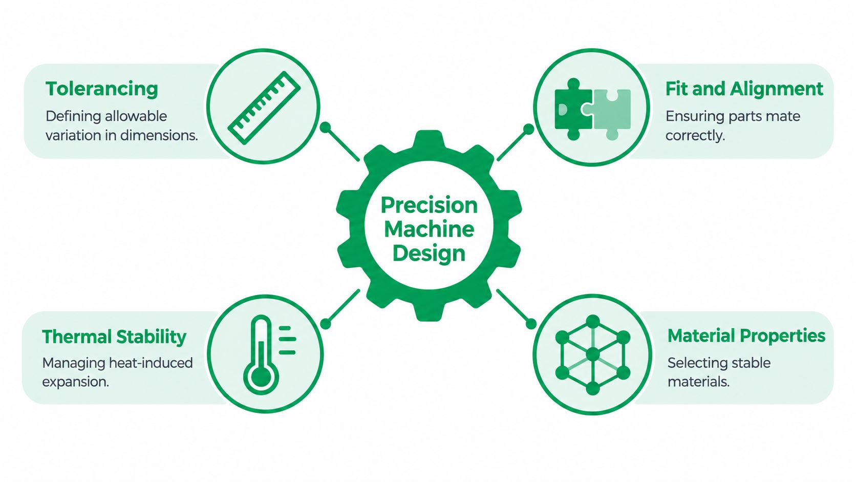
Tolerancing sets the permitted variation on a feature. It is not a claim that every dimension deserves the tightest limit you can write. Identify the dimensions that control fit, motion, sealing, alignment, or load transfer, then allocate limits that protect those functions and no more. A bearing seat governs how a rotating joint behaves; the non-mating housing face beside it usually does not.
Allocation should come from measured process capability rather than habit or CAD defaults. When a callout sits tighter than what the process holds consistently, the tighter number doesn't produce better parts. It produces inspection arguments, scrap, and rework, which is why I check capability data or a supplier's documented results before finalizing limits on anything that moves, seals, or locates.
Fit and alignment describe how parts locate and work together. Furniture fails the same way: every board can hit its nominal length and the finished piece still racks if the reference edges don't line up. Datums and geometric tolerances make those relationships explicit on a machined assembly. A hole's position relative to a functional datum often matters more than the hole's size in isolation.
Explicit datums pay off twice. They let a CMM verify position directly, and they let a newer operator set up correctly without decoding a senior machinist's unwritten conventions, which matters as experienced setters get harder to find.
Control heat and structural movement
Heat is easy to underestimate and expensive to chase after the fact. A steel scale left in the sun grows; a machine's structural loop changes shape as motors, bearings, cutting, ambient swings, and friction add heat unevenly. NIST identifies thermal errors as a major contributor to machine-tool accuracy loss, and its research explains why a single expansion-coefficient calculation falls short: temperatures vary across the structure and shift with operating conditions. Its guidance covers reducing heat generation, isolating or symmetrizing heat sources, shortening the distance between heat sources and the work zone, and running controlled warm-up procedures.
For CNC production, characterize the machine from a cold state across the expected temperature range and duty cycle rather than trusting one ambient-temperature calibration. Validate dimensional drift on representative parts or artifacts after repeated full-axis movement, then decide whether the process needs temperature-based compensation or an inspection trigger. As NIST's thermal-error research describes, in-process optical measurement paired with compensation has driven machined-part errors down to within measurement uncertainty, in cycles short enough to sit inside a production run rather than interrupt it.
Design for stiffness and dynamics together
Kinematic stability covers how the machine, tool, fixture, and workpiece respond under load and motion. A rigid frame guarantees nothing if the toolholder, fixture, joints, or the part itself flexes during the cut. Stiffness, damping, and dynamic behavior have to be engineered together: harmonic or modal analysis can flag resonances that amplify vibration, and impact or operational tests check whether the simulation matches the hardware. Research into dynamics-driven precision machine design makes the same point, placing structural behavior alongside sensors and control in determining positioning accuracy.
The question worth asking isn't "How rigid is the frame?" It's "Will the complete load path keep tool-point deflection inside the allowable limit for this part, cut, and tool orientation?" Precision comes from the system, not one spec.
Matching Design Choices to Manufacturing Processes
The right process depends on the feature, production stage, volume, and verification plan. A process that suits a complex metal prototype may be wasteful for a repeated plastic enclosure, while a process that produces a consistent molded part may require tooling and design commitment that doesn't make sense for an early iteration. The table is a planning aid, not a promise of a universal tolerance: actual capability depends on material, geometry, machine condition, setup, and inspection.
| Process | Typical Tolerance | Best For | Considerations |
|---|---|---|---|
| Multi-axis CNC machining | Set from feature geometry and supplier capability | Metal or plastic parts with machined datums, bores, and complex access requirements | Tight features may need careful fixturing, tool selection, and inspection |
| Additive manufacturing | Varies by process, material, and feature size | Design exploration, internal geometry, and functional prototypes | Surface finish, orientation, and post-processing can affect dimensions |
| Injection molding | Set around resin, tooling, and part geometry | Repeatable plastic components after design and tooling are established | Shrinkage, draft, wall consistency, and tooling investment matter |
| Sheet metal fabrication | Depends on material, thickness, bend geometry, and process | Enclosures, brackets, panels, and formed components | Bend allowances, springback, and feature placement affect fit |
| Vacuum casting | Depends on mold quality, resin, and part geometry | Appearance models and small-batch polymer parts | Suitable for bridge builds, but silicone molds and resin parts have process limits |
Choose the process around the critical features
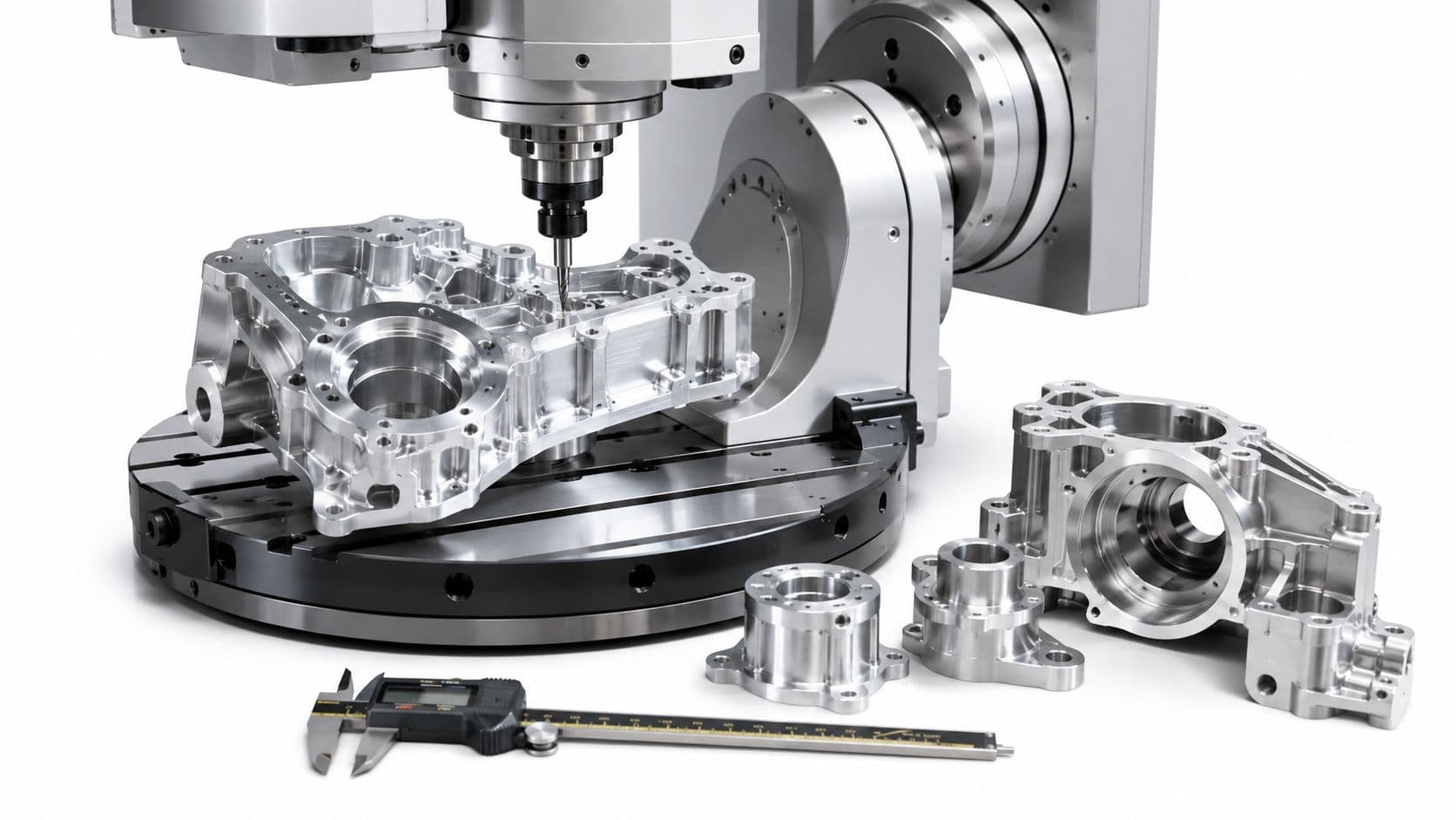
Multi-axis CNC machining is useful when datums, bearing seats, bores, or intersecting faces need controlled relationships. A 5-axis setup can reach multiple faces without repeated reclamping, but it still needs a stable fixture and a clear datum strategy. Don't assume that more axes automatically solve a setup problem.
Additive manufacturing supports fast form and fit evaluation, especially when a prototype needs geometry that would be difficult to machine. It may not be the right choice for a final mating surface without a finishing operation. Injection molding shifts the trade-off: once tooling and the design are settled, it can support repeatable production, but changes to geometry can become expensive.
Sheet metal fabrication suits formed enclosures and brackets, where the design must account for bend sequence, springback, and how features relate across bends. Vacuum casting can help make small batches of polymer parts or appearance models without committing immediately to production molding. To connect those process choices to design decisions, use a practical design-for-manufacturability review before releasing the part.
A process is only “capable” for your part when its setup, material, inspection, and acceptance criteria have all been considered.
DFM Checklists and Tolerance Selection
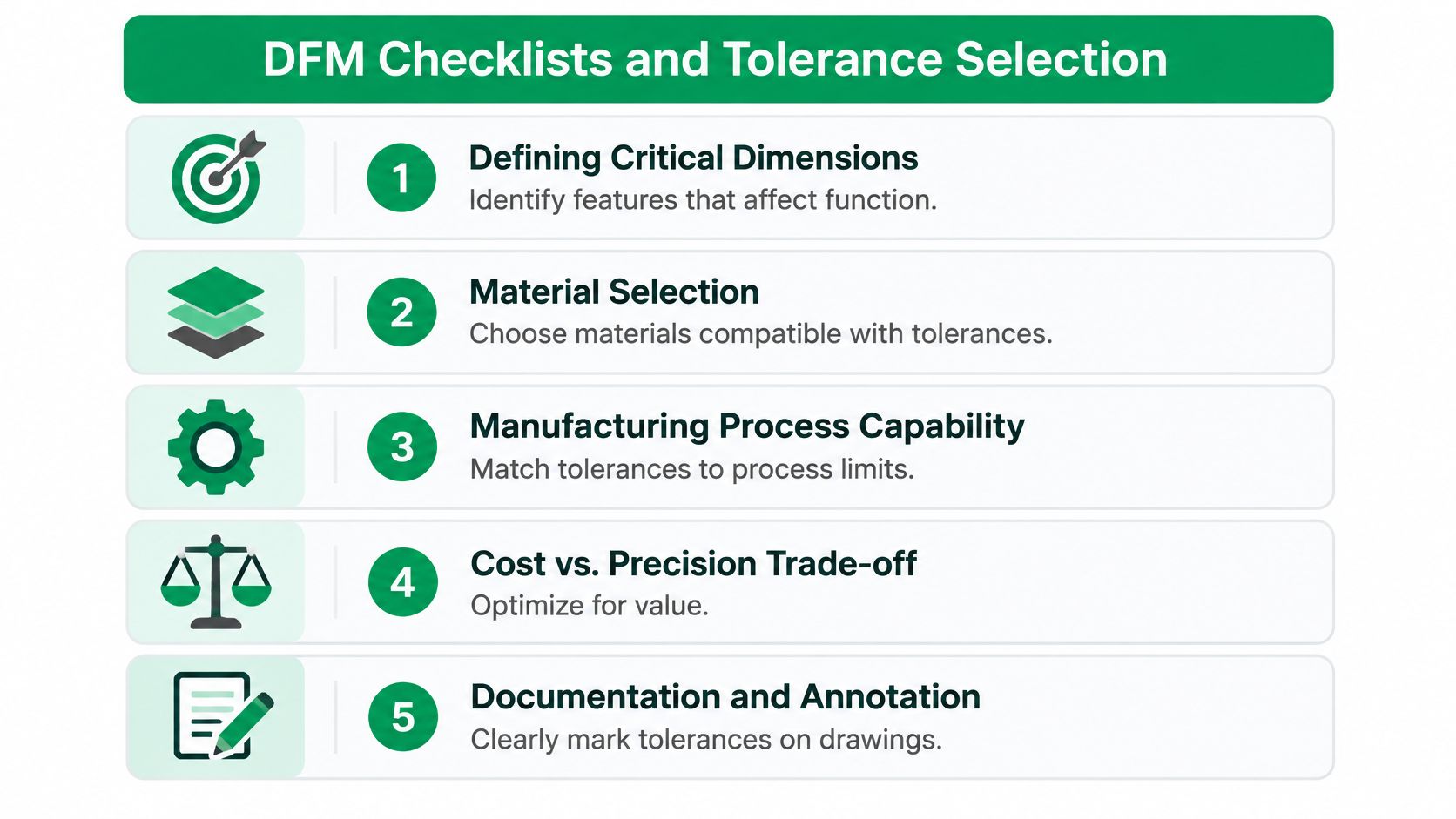
A useful drawing answers two questions: which features must work, and how will the team prove they work? Start by separating dimensions into functional, critical, and cosmetic groups. A critical feature affects safety, motion, sealing, or a key interface. A functional feature affects fit or assembly. A cosmetic feature affects appearance but doesn't control the mechanical function.
A drawing and process review
Before release, check whether the design provides:
- Functional datums: Reference features that match how the part is located in assembly and inspection.
- Short, symmetric force paths: Geometry that reduces bending and uneven loading during machining or use.
- Supported features: Fewer long, unsupported overhangs that invite deflection or vibration.
- Purposeful tolerances: Tight limits only where function requires them, with cosmetic requirements kept separate from load-critical GD&T.
- Accessible inspection: Features that a probe, gauge, CMM, or other planned instrument can reach repeatably.
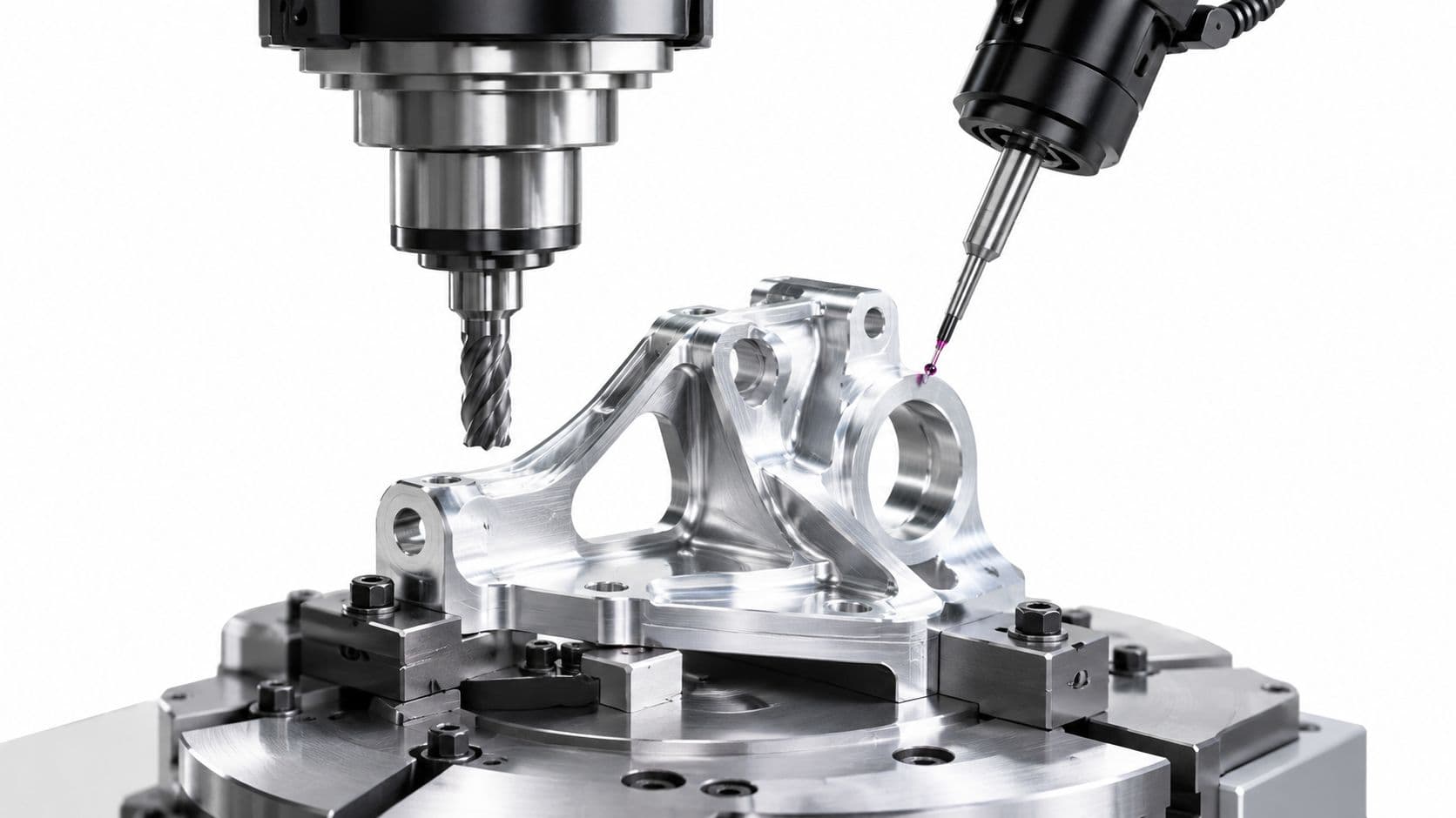
Then pair each important feature with an acceptance method. A probe may check a machined feature while the part remains set up; a post-process inspection can verify the finished relationship; a functional gauge may answer a fit question directly. If no practical method can verify a requirement, revisit the tolerance, datum scheme, or part geometry before production.
Measurement-driven adjustment can be more rational than applying the same tight limit everywhere. A study reported that automated probing reduced setup uncertainty from 0.03 mm to 0.002–0.003 mm, while active laser scanning limited combined wear and thermal-error deviation to about 0.005 mm in one machining procedure. It also reported that dynamic tolerance reallocation increased effective component tolerance by 46% and improved Cpk from 1.29 to 1.85 in a production-scale study, as summarized in the research on measurement-driven tolerance allocation.
Those findings don't mean every part needs scanning or dynamic reallocation. They show why a tolerance plan should consider measurement and compensation, not just nominal machine accuracy. For parts with interacting dimensions, a tolerance stack analysis can help determine which limits control assembly.
Inspection and Quality Control Practices
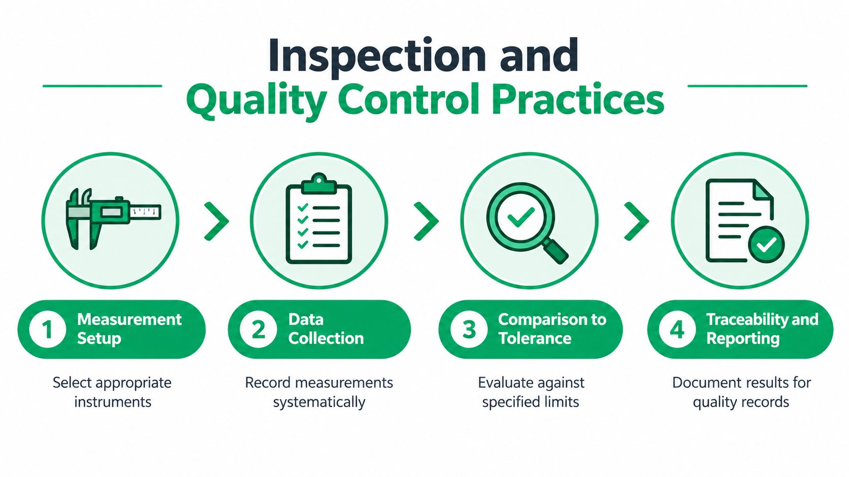
A tolerance on a drawing is a requirement, not evidence that the part meets it. Verification starts with choosing a measurement method that can reliably assess the feature and its relationship to the datum scheme. A caliper might suit a straightforward external dimension, while a coordinate measuring machine or in-process probe may be more appropriate for a position relationship or a feature that needs to be checked in its machining setup.
Build verification into the process
The inspection plan should identify the datum setup, instrument, feature, acceptance criteria, and record required. In-process probing can catch setup shifts before a machining cycle continues. Post-process inspection can verify finished dimensions and relationships after the part is removed from the machine. Neither method replaces the other in every situation: the choice depends on what could change during the remaining process steps and how the feature will function.
Measurement uncertainty matters. If the method can't distinguish an acceptable result from an unacceptable one with confidence, the inspection plan may produce false passes or false failures. Define how the part is supported, where the probe or instrument contacts it, and whether temperature or surface condition could affect the reading. Train inspectors to use the same datum reference and evaluation method.
Documented quality systems, including ISO 9001 and ISO 13485, support controlled processes and traceable records. The practical value comes from the work instructions, inspection records, and change control that help different people produce and evaluate parts consistently. For a closer look at how inspection connects to production controls, see this guide to quality control in manufacturing.
If inspection depends on an unwritten setup trick, the process isn't fully controlled.
Application Examples Across Industries
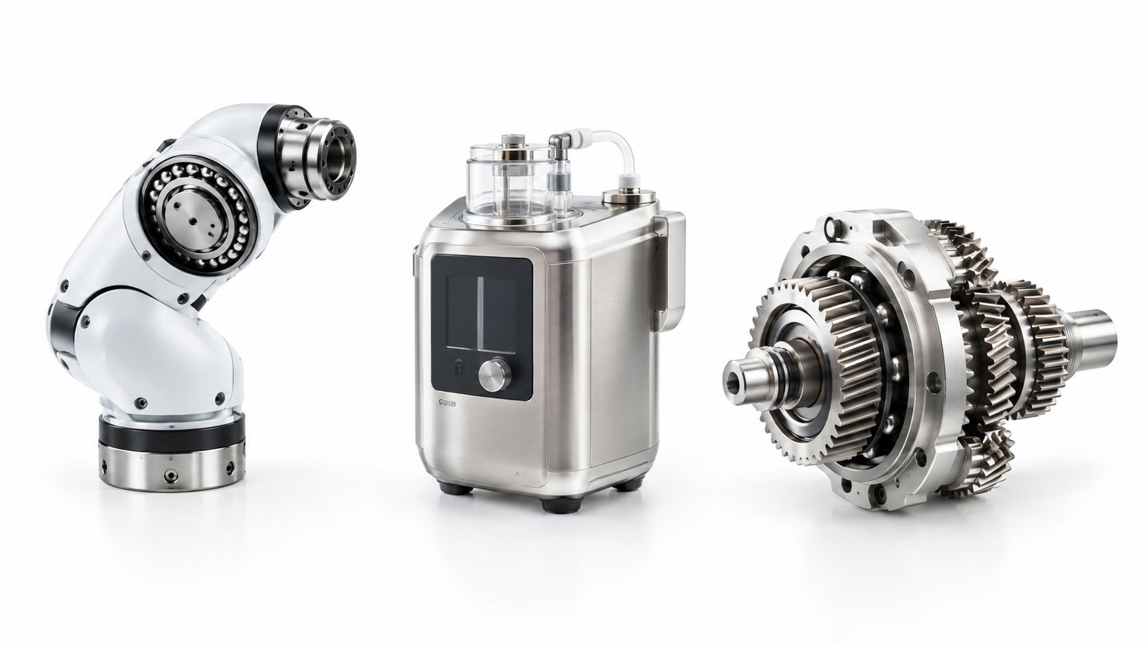
Consider a robotic joint housing. The bearing seat and mounting interface establish how the joint rotates and attaches to the arm, so those features deserve a clear datum strategy and a measurement plan tied to the assembly. An exterior face that doesn't locate another component may need a looser dimensional requirement, even if its finish still matters visually. Machining the housing from a stable setup can preserve relationships between important features, while inspection verifies the interfaces that control motion.
Make the requirement fit the application
A medical device enclosure must satisfy both dimensional and material requirements. Features that mate with another housing half, retain a component, or support an interface need deliberate tolerances and verification. The enclosure's cosmetic surfaces can be controlled separately, and the material and finishing process must suit the product's intended use. A prototype may be machined or printed to test fit and assembly before the design moves to a production method.
Automotive parts show why process sequence matters. A steering-related component may need its bearing seats, tooth geometry, and alignment features to remain functional through multiple operations. Heat treatment can change geometry, so the manufacturing plan may need a finishing operation after treatment and an inspection point to confirm the resulting features. That plan should reflect the actual process chain, rather than assume the first machining operation defines the final condition.
Across these examples, the useful question is not “What tolerance does this industry use?” It's “Which interface controls function, what process creates it, and how will the team verify it?” A robotic bearing seat, a medical enclosure interface, and an automotive gear feature have different consequences when they drift. Their requirements should reflect those consequences, not a blanket preference for tight dimensions.
Designing for Real Process Capability
Tighter tolerances don't automatically make a better part. They can increase machining and inspection demands without improving how the product works. Closed-loop measurement and selective compensation may be more effective than tightening every feature uniformly, particularly when the team can identify which dimensions drive function and measure them during the process.
That approach only works if the drawings and work instructions communicate intent clearly. Use unambiguous GD&T, consistent datums, accessible inspection features, and process plans that record what was measured and how. Reduce unnecessary tool changes and setups where practical. A part that requires one specialist to interpret an ambiguous drawing is harder to reproduce reliably across shifts or suppliers.
Workforce resilience is part of manufacturability. A 2026 manufacturing report states that 79% of manufacturing leaders identified skilled labor shortage as a major external challenge, up from 72% in 2025, and notes that complex manufacturing still depends on trained workers and integrated automation, as reported in the gear-industry outlook. Automation can support repeatability, but it doesn't remove the need for clear engineering intent, sound setup decisions, and capable inspection.
When a process struggles to hold a requirement, diagnose the reason before tightening controls or blaming the machine. Check the datum scheme, fixture stiffness, tool access, heat effects, and measurement method. If the feature still can't be made or verified economically, redesign may be the more precise engineering decision.
Frequently Asked Questions
What's a realistic tolerance for CNC machining?
There isn't one universal value. Set limits from the feature's function, material, geometry, setup, and the supplier's demonstrated capability, then agree on how the result will be inspected.
Should I use CNC or injection molding for a low-volume run?
CNC is often practical when geometry may still change or the part needs machined interfaces. Molding becomes more attractive when the design is stable and repeatability across a run justifies tooling.
What's the difference between a functional datum and a cosmetic surface?
A functional datum locates the part for assembly, operation, or inspection. A cosmetic surface mainly affects appearance and shouldn't control functional relationships unless it also serves as a locating interface.
How do I verify a part meets its tolerance?
Specify the measurement method, datum setup, and acceptance criteria alongside the drawing. Match the instrument to the feature, and make sure the inspection can distinguish acceptable from unacceptable results.
FIRMFG supports CNC machining, additive manufacturing, sheet metal fabrication, molding, and casting for prototype and low-volume production, with DFM feedback and documented inspection processes. Share your part requirements and target use to discuss a process and verification plan suited to the design.