Precision CNC Machining: Tolerances, Materials, and Sourcing
You've got a launch date, a bracket that has to locate two mating parts without play, and three quotes that don't agree on price or lead time. One shop says the tolerance is routine. Another wants a drawing change before they'll commit. The difference isn't sales language. It's whether the shop can machine, hold, and prove the dimension through a full run.
That gap between a number on a print and a part that assembles cleanly is where most precision programs succeed or stall.
Table of Contents
- What Precision CNC Machining Actually Means in Practice
Why a Machine Brochure Is Not a Process Plan
The Decision Flow That Prevents Rework
From 3-Axis to 5-Axis and Micro Machining- What the Fourth and Fifth Axes Actually Buy You
How Materials and Tolerances Drive CNC Machining Cost- How Material Choice Changes the Tolerance Conversation
Design for Manufacturing Tips That Save Real Money- Drawing Choices That Move the Quote
Inspection Methods That Protect Tight Tolerances- Matching the Instrument to the Feature
How to Evaluate a Precision CNC Machining Supplier- Evidence to Request Before You Commit
Key Takeaways and Next Steps for Your RFQ- A Compact RFQ Checklist
What Precision CNC Machining Actually Means in Practice
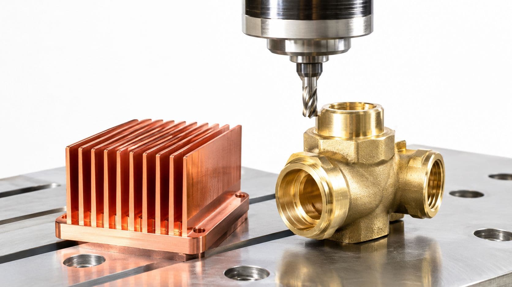
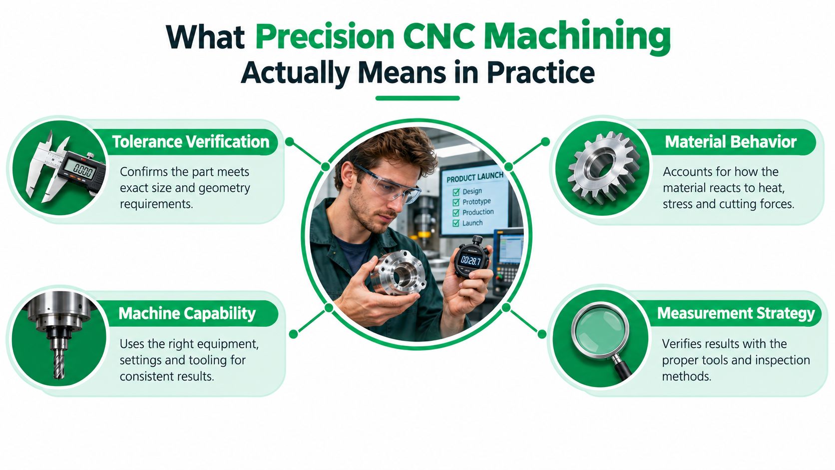
Take that bracket. On CAD it looks simple, a flat body, a few holes, one bore that locates a shaft. In the shop, the bore position depends on how the blank is fixtured, whether the material moves when clamps release, and whether the machine is cold or has been cutting for two hours. Precision CNC machining isn't a single machine specification. It's a system that connects machine capability, process control, material behavior, and inspection.
A useful way to judge precision is to split it into four questions. Can the shop hit the target dimension on the first part? Can it repeat that result on the last part in the batch? Does the surface finish support the function, such as sealing, sliding, or fatigue life? Can the shop measure the feature with a method that matches the drawing?
Why a Machine Brochure Is Not a Process Plan
A modern mill can position very accurately under controlled conditions, but your part doesn't live under test conditions. Tool wear changes size. Thin walls deflect under cutting force. A long tool in a deep pocket vibrates where a short, rigid tool wouldn't. Even the order of operations matters, because roughing one side first can release stress and shift a datum you planned to finish later.
That's why experienced buyers don't ask only what tolerance a shop advertises. They ask how the shop will fixture the part, which features will be finished in the same setup, and what will be checked before the batch continues.
A tolerance is only real if the shop can produce it repeatedly and show you measurement evidence from the actual run.
The Decision Flow That Prevents Rework
Start with function, not habit. Identify the features that control fit, alignment, sealing, or motion. Put your tightest controls there. Let noncritical faces, clearances, and cosmetic areas carry more generous limits. Then match that intent to a machine class, a material that behaves predictably, and an inspection method that can verify the result.
When those four choices align, quoting gets faster and parts arrive ready to assemble. When they don't, you pay for extra setups, secondary operations, scrap, and inspection arguments. Precision is therefore a buying discipline as much as a machining discipline.
From 3-Axis to 5-Axis and Micro Machining
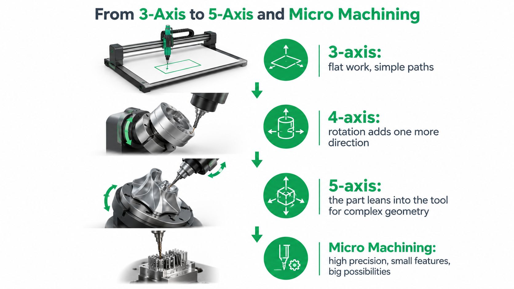
Think of a 3-axis mill as a pen plotter with depth. The tool moves left and right, forward and back, and up and down over a part that stays in one orientation. That covers a large share of brackets, plates, enclosures, and pocketed housings. If every critical feature can be reached from one or two straightforward setups, 3-axis work is usually the most economical route.
The limitation appears when features sit on several faces. Each refixturing creates a chance for location error between faces. A good shop manages that with probed datums and careful workholding, but the setup count still drives cost and lead time.
What the Fourth and Fifth Axes Actually Buy You
A 4-axis machine adds rotation, so the part can index or turn toward the tool. That's valuable for features around a cylinder, cross holes, flats on a shaft, and parts that would otherwise need repeated manual repositioning. It doesn't automatically make a part more accurate. It reduces handling and keeps related features tied to a common setup.
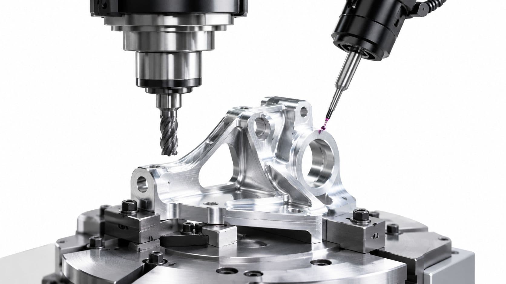
With 5-axis machining, the part or tool can also tilt. Picture the workpiece leaning toward the cutter so a short, rigid tool can reach an angled face or curved surface without a special fixture. That matters for undercuts, organic contours, deep cavities with drafted walls, and medical or aerospace geometry where several angled features must relate closely to each other. For a deeper look at when that capability pays back, review how shops apply 5-axis CNC milling to complex multi-face parts.
There's a trade-off. Five-axis programming, collision checking, and machine time cost more, and a careless toolpath can still leave poor finish. Use it when geometry or setup reduction justifies it, not as a badge on an RFQ.
Turning, Micro Machining, and Wire EDM
Round parts belong on a lathe first. CNC turning controls diameter, roundness, and concentricity efficiently because the workpiece rotates against the tool. Mill-turn equipment can then add flats or cross holes without moving the part to another machine.
Micro machining addresses very small features where tool strength, spindle runout, and chip evacuation become the limiting factors. Wire EDM becomes a practical choice for sharp internal corners, narrow slots, or hardened tool steel that carbide cutters struggle to machine economically. It cuts slowly, but it doesn't depend on tool force in the same way as milling.
Choose the process by geometry and feature relationship. The cheapest machine hour can become the most expensive part if it needs three extra setups to finish.
How Materials and Tolerances Drive CNC Machining Cost
A drawing goes out for quote with a single tight tolerance applied to every dimension. The shop slows feeds, adds finishing passes, inspects features that never touch anything, and still scraps parts that would have worked. Relax the dimension that controls a press fit or bearing seat, and the savings last right up until assembly. Tolerance is a cost lever set at the drawing stage, and the buyer holds it.
Precision CNC machining works best when tolerance allocation follows function. Bearing bores, mating faces, locating holes, and sealing surfaces deserve close control. Outside profiles that only need clearance usually don't.
How Material Choice Changes the Tolerance Conversation
Aluminum machines quickly and generally produces a clean finish, yet thin sections can deflect and large flat parts can move as material comes off. Steels bring strength and wear resistance, but they raise tool wear and cutting force, and some grades respond differently during finishing. Engineering plastics resist corrosion and cut weight, though they flex under clamping, expand with heat, and creep under load. A metal tolerance copied onto a plastic drawing is a common source of rejected parts.
Material choice also sets the stock strategy. A part machined from thick plate can carry internal stress that shows up after roughing. A near-net-shape blank reduces removal, provided its datums and machining allowances were planned in. Before locking a print, compare machinability, stability, and finishing needs with a practical guide to CNC machining materials and their trade-offs.
Precision CNC Machining Material and Tolerance Decision Table
| Material | Typical Tight Tolerance | Default Finish Range (Ra) | Process Upgrade Needed |
|---|---|---|---|
| Aluminum alloys | Tight control is routine on stable, well-fixtured features | Standard as-machined, finer on specified faces | 5-axis for multi-face geometry, careful workholding for thin walls |
| Carbon and alloy steels | Tight control is achievable, with more attention to tool wear | Standard as-machined, finer where function requires it | Rigid setups, wear monitoring, EDM for hardened or sharp internal features |
| Stainless steels | Tight control demands controlled heat and tool condition | Standard as-machined, specified finish on sealing faces | Sharp positive-rake tooling, controlled coolant temperature, tool-wear checks between batches, slower finishing passes on sealing faces |
| Engineering plastics | Metal-style tight limits need case-by-case review | As-machined finish varies by polymer and tool sharpness | Low-stress fixturing, sharp tools, temperature-aware inspection |
Surface Finish Depends on More Than Feed Rate
Buyers often assume a slower feed always produces a proportionally smoother surface. That stops being true at low feeds. Research on aluminum machined with round-nose carbide tools found the insert edge radius controls attainable roughness once feed drops low enough: measured peak-to-valley roughness Rz reached approximately 0.02 times the insert edge radius when machine-tool limits were avoided, as reported in research on edge radius effects in precision turning.
Past that point, cutting feed further adds cycle time without measurable gain. Tool wear, vibration, runout, coolant, and material behavior take over. Steel behaves differently from aluminum, so a finish recipe proven on one material needs a test cut on the other before it goes on the traveler.
Practical rule: Specify Ra or Rz only where sealing, friction, fatigue, or appearance requires it, and agree on the measurement method before production.
Tolerances near the tight end of normal practice are routine when geometry is accessible, material is stable, and inspection is straightforward. They stop being routine when a feature is deep, thin, angled, very small, or spread across several setups. The cost curve is rarely set by the number in the tolerance block. It is set by what that number forces on the floor: extra fixturing, special tooling, slower inspection. Before signing off, ask the shop which features are driving the quote.
Design for Manufacturing Tips That Save Real Money
Good DFM doesn't mean redesigning your product around a machine shop. It means removing the few features that force fragile tools, extra setups, or inspection methods nobody priced into the quote. Most drawings need only a handful of targeted changes.
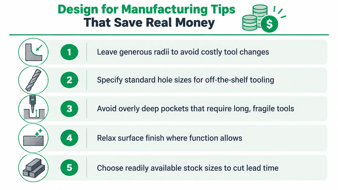
Start inside the pockets. A sharp internal corner can't be produced by a rotating round cutter, so the shop must use a smaller tool, add EDM, or ask for relief. A generous radius lets a standard end mill finish the corner quickly and leaves a stronger part.
Drawing Choices That Move the Quote
- Use standard hole sizes: Standard drills, reamers, and taps reduce tool changes and make thread and bore inspection simpler.
- Limit deep narrow slots: Long, thin tools deflect, break, and leave tapered walls, so widen the slot or reduce depth where function allows.
- Put datums on machinable faces: Datums should be surfaces the shop can fixture against and probe, not cosmetic edges or theoretical intersections.
- Mark functional tolerances clearly: Tighten locating and mating features, then let clearances and nonmating profiles carry general tolerances.
- Design for clamping: Leave a flat, solid surface for workholding or expect a custom fixture in the price and schedule.
- Avoid unnecessary undercuts: An undercut may require special cutters, a tilting setup, or a secondary operation that affects every part.
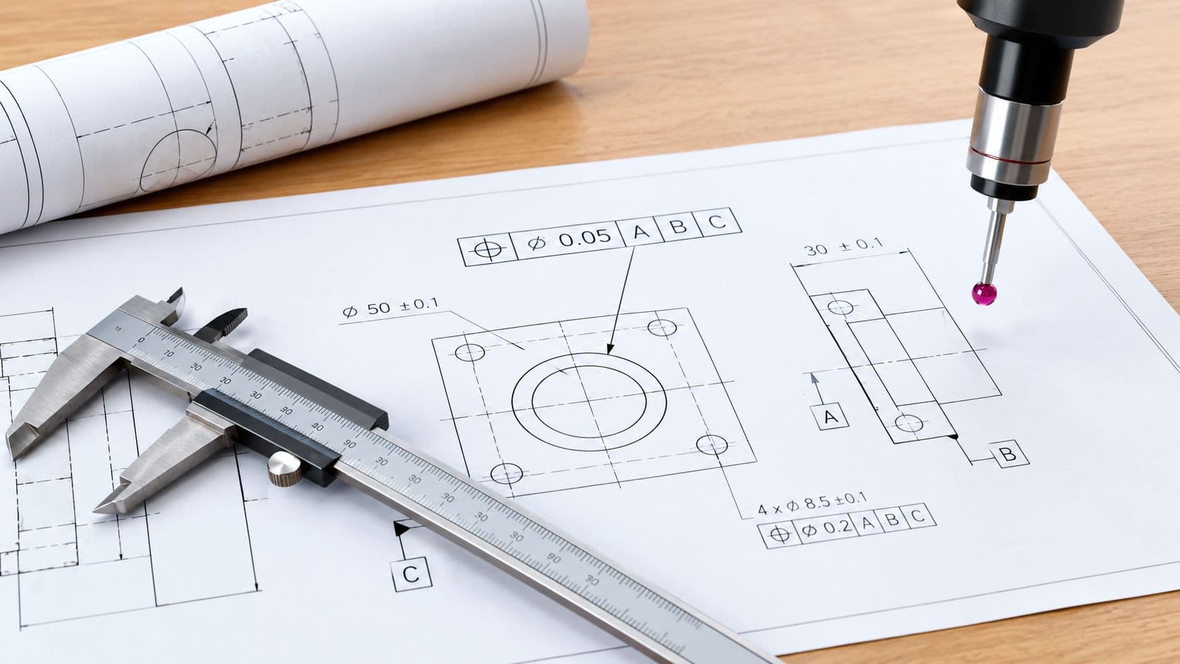
Datums deserve special attention because they connect machining and inspection. If your datum structure matches how the part sits in the fixture and later sits on the CMM, the shop can probe the same references it machines from. If it doesn't, every measurement becomes a translation exercise and disputes become more likely.
Build Thermal Stability Into the Plan
DFM also includes the conditions under which final dimensions are produced. Thermal effects can contribute up to 75% of total geometrical error in a machined part, so controlled warm-up, stable coolant, and inspection after representative spindle activity belong in any serious DFM plan, consistent with NIST research on thermal error in machining.
Ask the shop when finishing passes will run relative to warm-up, and whether first-off inspection happens after the machine has reached a representative state. A part measured right after startup can pass while later parts drift as the spindle, axes, and structure expand.
Before you send an RFQ, review the drawing for the smallest internal radius, deepest narrow feature, thinnest wall, tightest nonfunctional tolerance, and hardest feature to inspect. Those five items usually explain most of the price.
Inspection Methods That Protect Tight Tolerances
A dimension isn't controlled because it's printed in a title block. It's controlled when the shop has a measurement method with enough resolution, a defined datum setup, and a sampling plan that catches drift before the batch is finished.
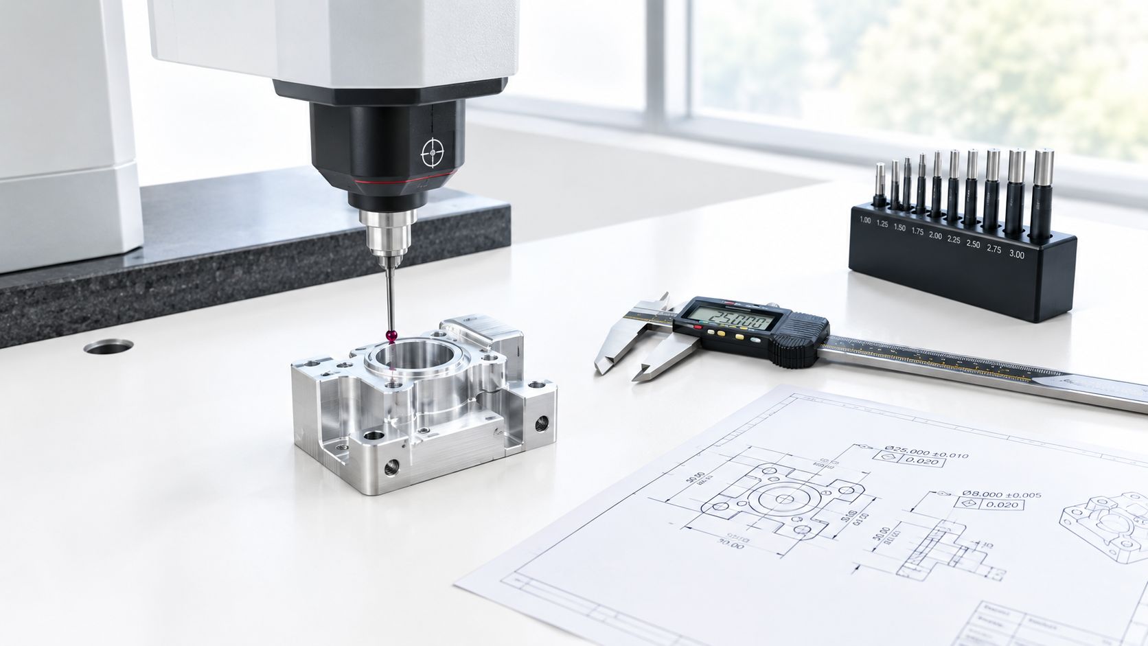
For routine lengths, diameters, and hole sizes, machinists use calipers, micrometers, bore gauges, and pin gauges at the machine. These tools are fast and effective when the feature is accessible and the tolerance suits the instrument. They also let an operator correct tool wear early instead of discovering a trend at final inspection.
Matching the Instrument to the Feature
A coordinate measuring machine, or CMM, earns its place when several features relate through GD&T, true position, profile, flatness, or parallelism. It measures from the datum structure rather than treating each size in isolation. If you're buying multi-feature parts, it's worth understanding what a proper CMM inspection service should document for your first article.
Optical comparators suit profiles, small radii, and thread forms that are difficult to probe. Surface profilometers verify Ra or Rz where finish affects sealing or friction. Thread gauges, hardness testing, and material certificates answer different questions again, so don't accept a generic statement that parts were inspected without knowing which method covered which requirement.
Timing Matters as Much as Equipment
The earlier thermal discussion has a direct inspection consequence. A cold machine check can confirm basic positioning, but it doesn't represent a spindle and structure after sustained cutting. Heat from motors, axes, the cutting zone, and room changes expands tools, workpieces, leadscrews, and the machine itself at different rates. Compensation based only on a simple expansion assumption can miss that uneven behavior.
A defensible control plan therefore uses a sequence:
- Warm up the machine: Run spindle and axis activity that resembles production before final finishing.
- Inspect the first-off part: Measure critical datums and dimensions in that representative thermal state.
- Check during the run: Set intervals based on tool wear risk, material, and tolerance sensitivity, not convenience.
- Confirm the final parts: Verify that late-run parts still match the approved first article.
Ask for the inspection report to name the instrument, datum setup, feature measured, and result. A pass stamp alone doesn't tell you how much margin remains.
For surface finish, request measurement on the actual material with the production tool, edge preparation, coolant strategy, and finishing pass. A sample coupon cut under different conditions won't protect a sealing face. The strongest first article package connects each critical drawing requirement to a measured result, so you can approve the process rather than hope the next batch behaves the same way.
How to Evaluate a Precision CNC Machining Supplier
Unit price is the easiest number to compare and one of the least complete. A low quote that excludes proper fixturing, finish, inspection, packaging, or material certification can become expensive after the first delivery fails assembly.
Evaluate the shop as a production system. You're buying programming judgment, workholding, tool management, measurement, communication, and capacity, not spindle time alone.
Evidence to Request Before You Commit
- Relevant certifications: Ask whether the quality system matches your sector, such as ISO 9001 for general manufacturing, ISO 13485 for medical work, or IATF 16949 capability where automotive controls apply.
- Equipment and capacity list: Look for machine classes that fit your geometry, plus turning, EDM, finishing, and inspection resources where your part needs them.
- Sample first article paperwork: A redacted report shows whether dimensions, materials, finishes, and traceability are recorded in a format your team can review.
- DFM response quality: Strong feedback names a specific radius, tolerance, datum, or access problem and proposes an alternative. A quote with no questions on a difficult drawing isn't always a good sign.
- Commercial terms: Confirm quoting speed, minimum order policy, revision handling, after-sales support, packaging, and shipping reach before a schedule problem tests them.
Industry classification gives procurement teams a useful sanity check when comparing domestic capacity data. In the United States, machine shops sit under NAICS 332710, the category federal agencies use for machining, turning, and milling establishments, as shown in the Bureau of Labor Statistics industry data for machine shops. That doesn't qualify an individual supplier, but it helps you separate machining specialists from broader fabrication businesses during market research.
Sustainability claims need the same evidence discipline. Don't compare shops on a generic eco-friendly label. Ask about material yield, chip recovery, coolant use and recycling, energy per run, and the boundary used for any carbon figure. Coverage of buyer requests for carbon-footprint data and material waste in titanium machining illustrates why measured sustainability data matters during CNC supplier qualification. Near-net-shape stock selection can matter more than a small machine efficiency gain when most of a billet becomes chips, although dry machining or reduced coolant won't suit every alloy, finish, or tool-life requirement.
As one example of a multi-process supplier model, FIRMFG offers 3-axis, 4-axis, and 5-axis milling and turning with micro machining, wire EDM, finishing, and inspection support for prototypes and low-volume metal and plastic parts. Judge any supplier, including that type of consolidated provider, against your drawing, documentation, capacity, and delivery requirements rather than a capability list alone.
Key Takeaways and Next Steps for Your RFQ
Precision CNC machining grew out of numerical-control research conducted in the United States during the 1940s and 1950s, with MIT publicly demonstrating a major numerical-control milling system in September 1952, a milestone described in the history of numerical control and its early milling systems. The tools have changed from punched tape to digital multi-axis control. The core discipline hasn't. A defined geometry must become controlled motion, then a measured part.
Keep that chain intact on your next RFQ.
A Compact RFQ Checklist
- State the function: Identify mating parts, critical fits, sealing faces, and features that only need clearance.
- Tolerance with intent: Tighten critical datums and interfaces, and relax nonfunctional dimensions and finishes.
- Choose material for stability: Consider machinability, stress movement, clamping behavior, finish, and inspection conditions, not strength alone.
- Match machine class to geometry: Use 3-axis where access is simple, rotary or 5-axis capability where setups or angles demand it, and EDM or micro machining for features conventional cutters can't handle well.
- Define proof: Request a first article report that ties each critical requirement to an instrument, datum setup, and measured result.
- Ask process questions: Cover fixturing, warm-up, in-process checks, tool wear controls, finishing, packaging, and revision management in the quoting exchange.
Decision rule: If a supplier can't explain how a critical feature will be held, finished, and measured, the quote isn't ready for approval.
Start with one drawing revision pass before you chase more quotes. Enlarge the radii that force tiny tools, fix datums that can't be probed, and remove tight limits that don't protect function. Then shortlist suppliers on DFM quality and inspection evidence, run a pilot batch, and release larger volume only after the first article proves the process.
Send FIRMFG your CAD files and drawing requirements for a DFM review covering material choice, tolerance risk, machine selection, and inspection planning for your precision parts. Our team supports CNC milling, turning, 5-axis machining, micro machining, wire EDM, and finishing for prototypes through low-volume production, so you can get a clear quote and a producible path forward by visiting FIRMFG.