Types of Fit: Clearance, Transition, and Interference
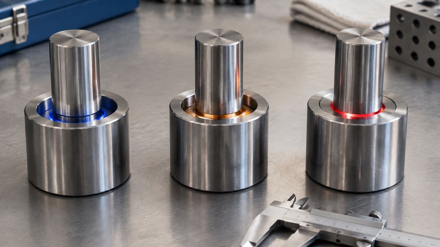
A shaft is meant to slide into a bore by hand. On the bench, one assembly drops in loosely while another needs a press. The drawing looked clear, but the parts tell a different story. Usually, the trouble began before machining: the drawing didn't define the intended relationship between the hole and shaft precisely enough.
Understanding the types of fit gives designers, machinists, inspectors, and assemblers a shared way to describe that relationship. But identifying a fit category is only the start. The useful question is what the assembly must do, and what measurable result will prove it works.
Table of Contents
- Why Fit Selection Trips Up Even Experienced Designers
- The Three Types of Fit Explained with Tolerance Zones
Clearance means a gap is guaranteed
Transition means the result depends on the actual parts
Interference means the shaft is always larger
How ISO 286 and ANSI Systems Organize Tolerance Grades- Basic-hole and basic-shaft systems
Common Fit Designations and What They Actually Do- Common Fit Designations and Their Typical Functions
A Function-First Framework for Choosing the Right Fit- Work backward from the required behavior
Why Tighter Tolerances Can Quietly Make a Part Worse- Verify what the assembly must do
Fit Behavior in Plastics Compared to Metals- Design for the material and process
Specifying and Inspecting Fits on Real Drawings
Why Fit Selection Trips Up Even Experienced Designers
A designer calls for a simple slip fit on a shaft and bore. The machinist makes both parts within their individual size limits, but the assembled parts either bind or rattle. Neither component is necessarily out of tolerance. The drawing may have allowed combinations that do not deliver the intended assembly behavior.
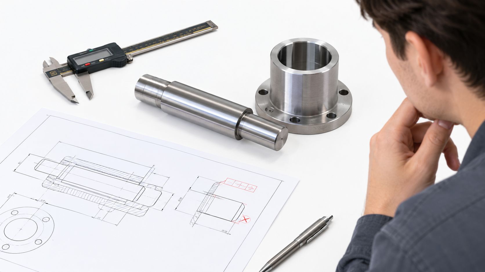
That's why fit classification matters beyond the shop floor. The recognized categories are clearance, transition, and interference. Each describes how the hole's tolerance zone relates to the shaft's tolerance zone, rather than relying on a loose phrase such as “snug” or “press in.” The system is formalized internationally through ISO 286, the standard for ISO limits and fits. The first edition was published in 1962, following the earlier ISA Bulletin 25, first issued in 1940. ISO 286 was later revised as ISO 286-1 and ISO 286-2, and the U.S. adopted the related metric system through ASME B4.2.
The value of that shared language is practical. A designer can specify the intended fit, a machinist can manufacture to the drawing, an inspector can check the dimensions, and an assembler can anticipate how the parts will come together. Without a clear fit definition, each person may interpret the same callout differently.
Design for the assembly, not for the label. A fit category describes the dimensional relationship. It doesn't, by itself, guarantee a particular insertion force, running feel, or service life.
The right fit depends on the assembly's function. A shaft that must rotate freely has different needs from a locating pin that should sit accurately but remain removable, or a hub intended to stay fixed to a shaft. Start with what the parts must do. Then choose a fit and tolerances that support that outcome.
The Three Types of Fit Explained with Tolerance Zones
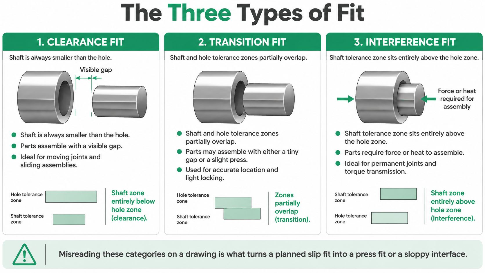
Think of the hole and shaft as two ranges of possible sizes, not as two perfect dimensions. Each range is a tolerance zone. Compare the zones, and you can predict whether every possible part combination will leave a gap, may produce either a gap or tightness, or always require force to assemble.
Clearance means a gap is guaranteed
In a clearance fit, the hole is always larger than the shaft. Even the largest permitted shaft is smaller than the smallest permitted hole, so the parts have a positive gap when assembled. That gap may allow sliding or rotation, depending on the design and other operating conditions.
For example, a rotating shaft in a housing may need clearance so it can turn without binding. The amount of clearance still matters: too little can cause friction or seizure, while too much may allow unwanted movement. The category tells you a gap exists, not whether it's appropriate for the mechanism.
Transition means the result depends on the actual parts
In a transition fit, the hole and shaft tolerance zones overlap. Some permitted combinations produce slight clearance; others produce slight interference. This is the category that often surprises designers who assume a fit name predicts one guaranteed assembly feel.
The reason is straightforward: the actual hole and shaft can fall at different points within their respective permitted ranges. A drawing that permits both outcomes may be suitable for accurate location, but it doesn't promise that every matched pair will assemble with the same force.
Interference means the shaft is always larger
In an interference fit, the shaft is always larger than the hole. The parts need a controlled assembly method, such as pressing or using heat or cooling to change their relative dimensions. Once assembled, the interference can help keep components together or transmit force.
The distinction is about the zones, not the names a team uses informally. If the zones never cross and the hole stays larger, clearance is guaranteed. If they overlap, either result is possible. If the shaft zone stays larger, interference is guaranteed.
How ISO 286 and ANSI Systems Organize Tolerance Grades
A fit callout combines two ideas: where a tolerance zone sits relative to the nominal size, and how wide that zone is. In ISO notation, a letter identifies the zone's position, while a tolerance grade identifies its width. Hole positions use uppercase letters and shaft positions use lowercase letters.
That distinction helps decode a drawing without treating the callout as a mysterious code. The letter tells you which side of the nominal size the tolerance zone occupies and where it sits in relation to the mating feature. The grade indicates the permitted dimensional variation. Together, the hole and shaft specifications determine whether their zones create clearance, transition, or interference.
Basic-hole and basic-shaft systems
Designers commonly organize fits around a basic-hole system or a basic-shaft system. In a basic-hole approach, the hole is held to a selected reference zone while the shaft tolerance is adjusted to create the desired relationship. In a basic-shaft approach, the shaft is the reference and the hole is varied.
The choice often follows manufacturing and design needs. A team may prefer to keep one feature consistent and adjust the mating feature, especially when a process or component constrains how one part can be made. Neither convention makes a fit better. The assembled relationship still needs to meet the design's functional requirements.
Read the standard behind the drawing
ISO 286 standardizes tolerance zones for cylindrical features and parallel surfaces, including the basic-hole and basic-shaft systems. It gives teams a common dimensional framework, but it doesn't select the correct fit for every bearing seat, sliding guide, locating dowel, sealed joint, or torque-transmitting hub. That selection requires application-specific judgment.
U.S. drawings may refer to the related metric system through ASME B4.2. Don't assume that a drawing's region or the use of metric units alone tells you which standard governs its tolerance values. Check the drawing notes, title block, purchase requirements, and customer specifications. If the governing system isn't clear, resolve that before quoting or manufacturing the parts.
The practical skill isn't memorizing every code. It's knowing how to identify the standard, interpret the hole and shaft zones, and verify that the resulting tolerance relationship suits the assembly.
Common Fit Designations and What They Actually Do
A designation can help narrow the options, but it isn't a universal promise about how an assembly will behave. H7/h6 is a familiar precision-fit example and a frequent chart lookup. It still needs to be checked against the application: the fit code alone doesn't account for operating temperature, surface condition, coatings, or the function the assembly must deliver.
The table below separates the broad use of each fit category from the specific code. Where the code isn't established by the drawing's governing standard and application, don't infer it from a generic chart.
Common Fit Designations and Their Typical Functions
| Fit Code | Type | Typical Assembly Function |
|---|---|---|
| H7/h6 | Depends on the specified tolerance zones and applicable standard | A common precision-fit reference; confirm the actual clearance and the required motion or location |
| Hole-and-shaft zones with guaranteed clearance | Clearance | Sliding or rotating interfaces that need a gap |
| Overlapping hole-and-shaft zones | Transition | Components requiring accurate location, where actual parts may have slight clearance or interference |
| Hole-and-shaft zones with guaranteed interference | Interference | Fixed assemblies such as a hub or gear mounted on a shaft |
The last three rows describe the relationship between zones, not additional fit codes. That's intentional. Assigning a code without the correct nominal size, governing standard, and functional requirement can create false confidence. Use the standard's tables for the actual limits, then check whether the resulting assembly meets its performance criteria.
Why a familiar code can still be wrong
Suppose a designer sees H7/h6 on a previous drawing and reuses it for a new shaft and bore. The new assembly might need to rotate freely, resist movement, or locate parts accurately while remaining removable. Those functions aren't interchangeable, even if the nominal dimensions look similar.
Likewise, calling a fit “precision” doesn't tell the supplier what matters most. If the assembly must slide, specify an allowable clearance or functional check. If it must transmit torque, consider how the interference and assembly process will be validated. If the parts must locate accurately but come apart during maintenance, define the acceptable assembly and removal behavior.
Charts are useful for translating a design decision into a standardized callout. They're poor substitutes for making the decision in the first place.
A Function-First Framework for Choosing the Right Fit
Begin with the assembly, not a table. Ask whether the joint needs to move, locate, or stay together under load. That answer rules out many unsuitable options before you start comparing tolerance callouts.
Work backward from the required behavior
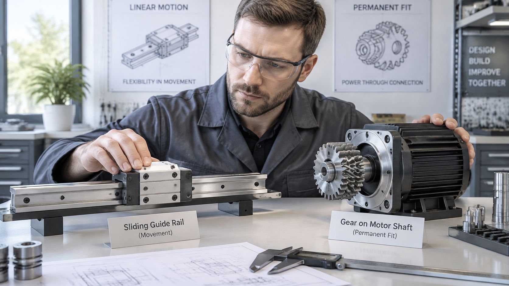
For a sliding guide in a precision instrument, the parts need controlled movement. Define what “slides smoothly” means in a way the team can assess, then consider the load direction, lubrication, surface finish, and conditions during operation. A clearance fit may be the starting category, but the acceptable clearance must still suit the guide's role.
For a gear mounted on a motor shaft, the goal is different. The interface may need to resist rotation relative to the shaft and transfer torque. An interference fit could be appropriate, but the designer must also consider the assembly method and whether future disassembly is required. For more detailed considerations around this type of joint, see press-fit calculation guidance.
Then work through the surrounding conditions:
- Required motion: Decide whether the parts must slide, rotate, locate, or remain fixed.
- Load direction: Identify whether forces may loosen, shift, or distort the joint.
- Assembly and service: Specify whether workers will press, heat, cool, or hand-assemble the components, and whether they must later come apart.
- Operating conditions: Account for temperature, lubrication, corrosion exposure, coatings, and surface finish.
- Inspection: Choose a way to verify the result, such as dimensional limits or an assembly-level functional check.
A tolerance code should follow those decisions. If the assembly's success depends on insertion force, runout, backlash, leakage, torque capacity, or allowable clearance at operating temperature, write that requirement down instead of expecting the fit label to carry the whole burden.
Why Tighter Tolerances Can Quietly Make a Part Worse
A tighter tolerance isn't automatically a better design. It may make a part harder to manufacture and inspect, while making the assembly more sensitive to conditions the drawing doesn't show. Specify only the control the function needs.
Consider a shaft and bore that fit well during room-temperature inspection. If their operating temperatures differ, their dimensions may change by different amounts. The resulting clearance or interference can shift, even though both components passed their individual checks. A fit chart alone can't tell you whether the assembly will remain free-moving or secure under those conditions.
Surface details matter too. A coating adds material to a surface, and roughness changes how two real surfaces contact compared with idealized dimensions. Contamination can further affect movement or seating. If a design depends on a very narrow dimensional window, these factors can turn a nominally acceptable fit into binding, looseness, or inconsistent assembly.
Verify what the assembly must do
The right inspection target depends on the function:
- Insertion force can help confirm that assembly effort stays within the intended range.
- Runout can reveal whether a rotating component sits or moves acceptably.
- Backlash can show whether a gear interface has the intended play.
- Leakage or torque capacity may be relevant when the interface seals or transfers force.
These checks don't replace dimensional inspection. They answer a different question: whether the assembled parts meet the behavior the design requires. A design may need both component-level limits and an assembly-level acceptance test.
Practical rule: Tighten a tolerance only when the function needs that control, and define how the team will verify the function.
If the drawing specifies a narrow fit but no acceptance criterion, the machinist may meet the dimensions while the product still disappoints. Conversely, a looser tolerance may work perfectly if the assembly's motion, location, and load requirements are satisfied. Better design means matching control to function, not maximizing precision for its own sake.
Fit Behavior in Plastics Compared to Metals
The clearance, transition, and interference categories still apply to plastic parts, but metal fit tables don't automatically predict how plastic assemblies will behave. Material response, manufacturing method, and operating conditions can all change the result. A tolerance relationship that works for a machined metal pair may be unsuitable for a molded or printed plastic pair.
Moisture absorption can affect some plastics, and thermal expansion can alter dimensions as temperature changes. Creep is another concern: under sustained load, a plastic part may gradually deform, which can change the contact pressure or loosen an initially tight joint. A fit that appears secure during a brief bench check might not remain so in service.
Design for the material and process
A molded bore and a machined bore aren't interchangeable just because their nominal dimensions match. Molded parts can show variation related to the tool, material behavior, and part geometry. Additive processes such as SLA, SLS, and FDM also produce surfaces and dimensions that differ from machined features. Vacuum-cast parts may behave differently again, depending on the resin and process.
For a plastic sliding guide, the design may need more clearance than a metal equivalent to avoid binding under expected conditions. For a press-fit feature, account for the plastic's tendency to deform and consider whether it must carry load over time. Don't assume that copying a metal-style tolerance callout will preserve the same assembly force or retention.
Material choice matters as well. ABS, polycarbonate, POM, and nylon don't behave identically, so don't treat “plastic” as a single engineering material. Check the selected resin's relevant dimensional and mechanical properties, along with the manufacturing process and intended environment. For guidance on process-specific dimensional controls, see injection molding tolerances.
Prototype parts are valuable for testing fit and assembly sequence, but they should represent the intended production material and process closely enough to answer the question being tested. If the prototype process differs, document what the trial can and can't validate.
Specifying and Inspecting Fits on Real Drawings
A useful drawing tells the supplier what to make and the inspection team what to verify. Put the governing standard and the hole and shaft requirements on the drawing, then identify any assembly-level behavior that matters. A fit code can communicate dimensional intent, but it won't replace a functional requirement when the joint's performance depends on one.
Before releasing a drawing or requesting a quote, check that:
- The fit is tied to the assembly function. State whether the parts must slide, locate, or remain fixed.
- The governing standard is unambiguous. Confirm the applicable ISO or ASME requirements in the drawing notes or specification.
- Critical geometry is controlled. Include relevant position, concentricity, or runout requirements where the assembly depends on them.
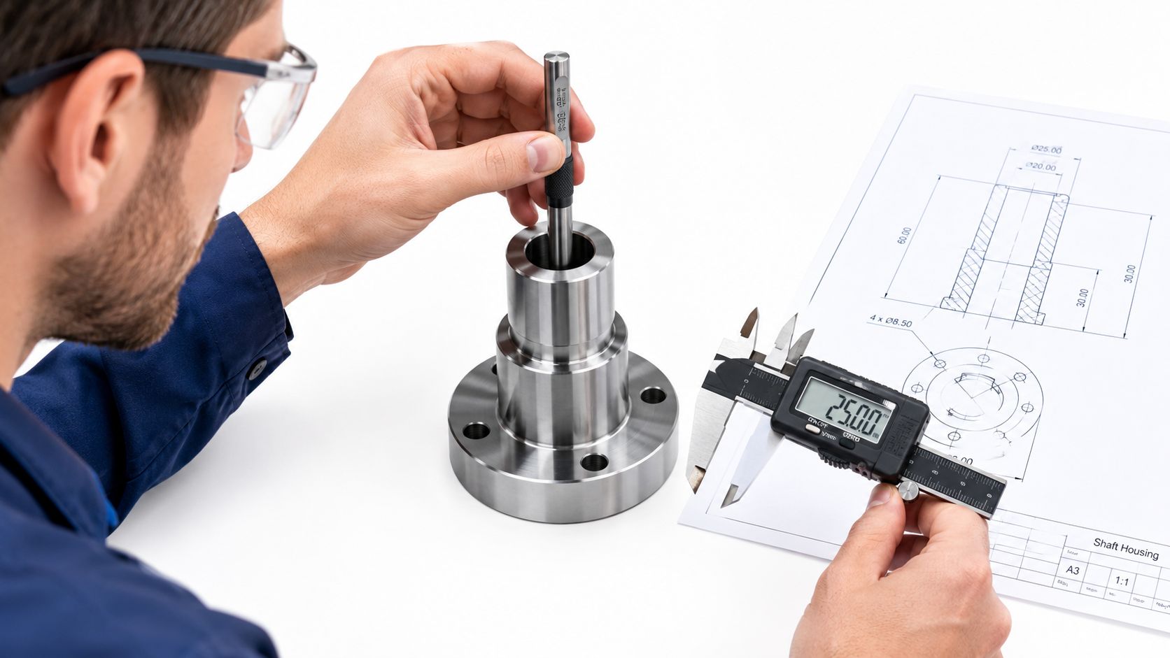
- The inspection method matches the feature. Pin or plug gauges, ring gauges, functional gauges, and a CMM serve different checks. Select a method suited to the specified geometry and acceptance criteria.
- Tolerance accumulation is considered. Review how the dimensions of mating parts combine at assembly. Tolerance stack analysis can help reveal when individually acceptable parts may produce an unacceptable assembled result.
A caliper reading alone may not establish whether a fit-critical bore meets its requirements. For an important interface, agree with the manufacturing partner on the measuring method, inspection conditions, and any assembly-level test before production begins.
The question to ask at drawing review is simple: What functional outcome must this fit guarantee, and how will we measure it? If the team can answer that clearly, the tolerance callout becomes a manufacturing instruction rather than a guess.
For prototype machining, molded parts, or low-volume production, FIRMFG offers manufacturing support that includes fit and assembly validation, inspection, and DFM feedback. Share your drawing and functional requirements with its team to discuss a practical route from design intent to verifiable parts.