Press Fit Calculations for Precision Machined Parts
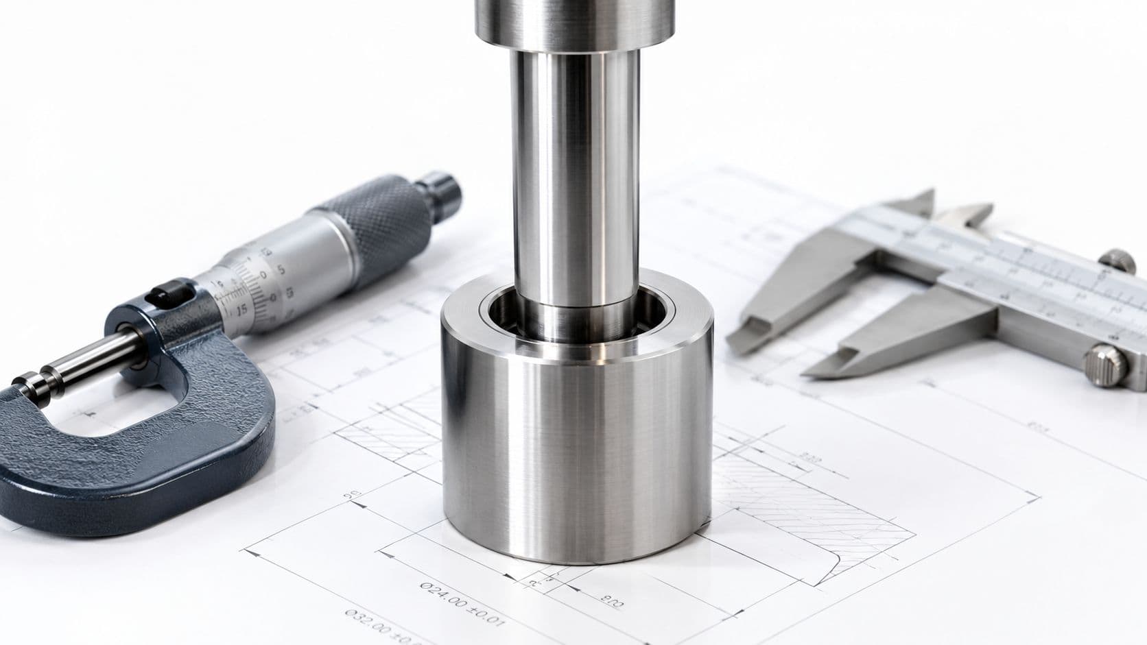
A press-fit assembly can look perfect in CAD and still fail at the assembly bench. The shaft and bore may both be labeled with the same nominal diameter, the model may show clean contact, and the drawing may appear complete. Then the machinist measures the parts, starts the press, and finds either a loose joint that slips into place or a fit so tight that the hub distorts before the shaft reaches its seating position.
That failure usually starts with an incomplete calculation. Press fit calculations must use the full tolerance stack, material behavior, operating temperature, surface condition, and assembly method, not just the difference between two nominal diameters. A joint survives because its actual minimum interference remains sufficient under load and its actual maximum interference stays below the limits of the parts and equipment.
Table of Contents
- Why Nominal Dimensions Fail in Press Fit Assemblies
Build the stack before choosing the fit
Worst case is a design boundary, not always a production forecast
Navigating ISO 286 Tolerance Standards for Interference Fits- Read the hole-basis designation correctly
Calculating Contact Pressure and Assembly Force Requirements- Start with the actual interference range
- Translate pressure into assembly force
- Separate retention from press capacity
- Know when statistical tolerance analysis belongs
Adjusting Interference for Material Pairs and Thermal Conditions- Compare the material pair, not just the shaft
Design for Manufacturability Rules for Precision Machined Fits- Give the assembly a controlled entry
- Specify the press zone deliberately
- Control location and coaxiality
- Plan the assembly operation with the part
Validating Your Press Fit Design Before Production- Use a staged validation sequence
Why Nominal Dimensions Fail in Press Fit Assemblies
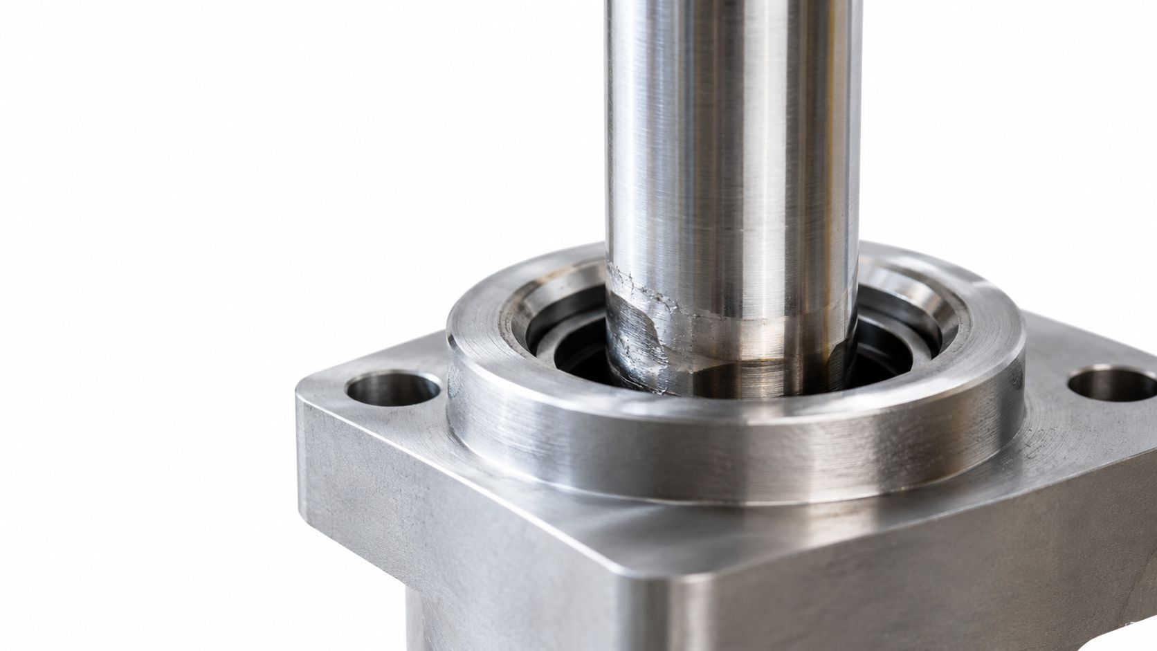
A nominal diameter is a design reference, not a measured condition. Consider a shaft and housing both called out around the same nominal size. The shaft can be produced near its upper limit while the bore lands near its lower limit, creating a difficult assembly. The opposite combination can produce little interference or even clearance, despite identical nominal labels in the CAD model.
That's why the first calculation should use the limits on the drawing:
- Minimum interference: smallest shaft diameter minus largest hole diameter.
- Maximum interference: largest shaft diameter minus smallest hole diameter.
- Actual condition: measured shaft diameter minus measured hole diameter for the parts being assembled.
The same nominal fit can therefore behave as a clearance, transition, or interference fit after manufacturing variation is included. The press-fit tolerance guidance from FabDigit emphasizes this distinction between nominal geometry and worst-case hole and shaft limits. The practical question isn't “What's the interference in CAD?” It's “What interference can the production process reliably deliver?”
Build the stack before choosing the fit
Start with the mating diameters, then add the conditions that can change the interface:
- Record the complete shaft diameter tolerance.
- Record the complete bore diameter tolerance.
- Calculate minimum and maximum diametral interference.
- Convert diametral interference to radial interference when required by the stress model.
- Check the hub wall geometry, engagement length, and material limits.
- Evaluate assembly force at both ends of the interference range.
This approach exposes two common design failures. A fit may have enough nominal grip but fail at its minimum interference, especially under vibration or torque. Another may retain the shaft securely at its minimum condition but crack, yield, or exceed press capacity at its maximum condition.
Worst case is a design boundary, not always a production forecast
Worst-case arithmetic assumes that every dimension reaches the unfavorable limit at the same time. That assumption is appropriate for safety-critical boundaries, low-volume production with limited process data, or any design where one bad combination can cause unacceptable damage. It can also be unnecessarily conservative when a stable, measured process produces tightly controlled distributions.
For production planning, engineers can compare the worst-case result with actual inspection data and process capability. A statistical tolerance approach may better describe the expected assembly population, but it must not replace a hard mechanical limit. If the maximum possible interference can plastically deform the hub, no favorable distribution justifies ignoring that condition.
Practical rule: Use worst-case limits to protect the design. Use measured process data to decide whether the manufacturing plan is unnecessarily restrictive.
The useful output isn't one interference number. It's a window that answers three questions: will the loosest acceptable parts retain the load, will the tightest acceptable parts assemble without damage, and can the supplier manufacture that window consistently?
Navigating ISO 286 Tolerance Standards for Interference Fits
ISO 286 gives engineers a common language for specifying controlled relationships between holes and shafts. Its hole-basis notation uses a hole designation such as H7 together with a shaft class such as p6, r6, s6, or t6. The designation communicates the location and grade of the tolerance zone, rather than leaving the machinist to interpret a vague instruction such as “light press fit.”
The modern system was codified through ISO 286-1:2010 and ISO 286-2:2010. Published references describe its scope across nominal sizes from 1 to 200 mm and define limit deviations for standard shaft classes including k6, n6, p6, s6, and u6. These details are summarized in the ISO 286 interference-fit table, which is useful when translating a design intent into limits that inspection can verify.
Read the hole-basis designation correctly
The hole-basis system keeps the hole's lower deviation at the reference position for an H designation, then shifts the shaft tolerance zone to create the required fit. That makes the hole practical to produce with standard reaming, boring, or finishing operations while the shaft diameter provides the interference adjustment.
The number after the letter is the tolerance grade. The letter identifies the position of the tolerance zone relative to the nominal size. The shaft letter then determines whether the resulting relationship is a light, medium, or high force fit.
| Fit designation | Classification | Typical application |
|---|---|---|
| H7/p6 | Light press fit | Retained components where assembly force and distortion must remain moderate |
| H7/r6 | Medium press fit | General interference assemblies requiring stronger retention |
| H7/s6 | Medium force fit | Shaft-hub joints, gears, bushings, and other load-bearing assemblies |
| H7/t6 | High force fit | Applications requiring substantial interference and controlled permanent retention |
These classifications are starting points, not permission to skip stress analysis. The published ISO fit values for press-fit design show why a small change in shaft class can shift the interference window materially. For nominal diameters in the 6–10 mm range, one table lists H7 as 0 / +15 µm, p6 as +15 / +24 µm, and s6 as +23 / +32 µm. The resulting calculated windows are 0–24 µm for H7/p6 and 8–32 µm for H7/s6.
For a 10–18 mm nominal diameter range, the same type of table lists H7 as 0 / +18 µm, p6 as +18 / +29 µm, and s6 as +28 / +39 µm. That produces 0–29 µm for H7/p6 and 10–39 µm for H7/s6. Each value comes from the stated hole and shaft limits, not from nominal subtraction.
Select the class around the failure mode
Choose the fit based on what must not happen. If the assembly must be removable without damaging either component, a lighter class may be appropriate. If the joint must transmit torque or prevent migration, a stronger interference class may be required, but the hub stress and assembly force must be checked first.
A bearing seat adds another constraint. Retention is only one objective, and excessive interference can reduce running clearance or distort the bearing geometry. Engineers working with sliding or bearing interfaces should distinguish these requirements from a simple shaft-hub retention problem. A practical reference on slip fit tolerance and clearance selection helps frame that contrast.
Finally, put the selected designation on the drawing and specify the datum scheme, inspection method, surface condition, and functional requirements. An ISO fit callout controls the dimensional relationship, but it doesn't by itself define the acceptable press force, lubrication condition, thermal assembly process, or service load.
Calculating Contact Pressure and Assembly Force Requirements
Once the tolerance class is selected, convert the interference range into physical consequences. The interface pressure controls frictional retention, while the same pressure contributes to hoop stress in the hub and compressive stress in the shaft. A fit that looks acceptable dimensionally can still exceed the material or equipment limits.
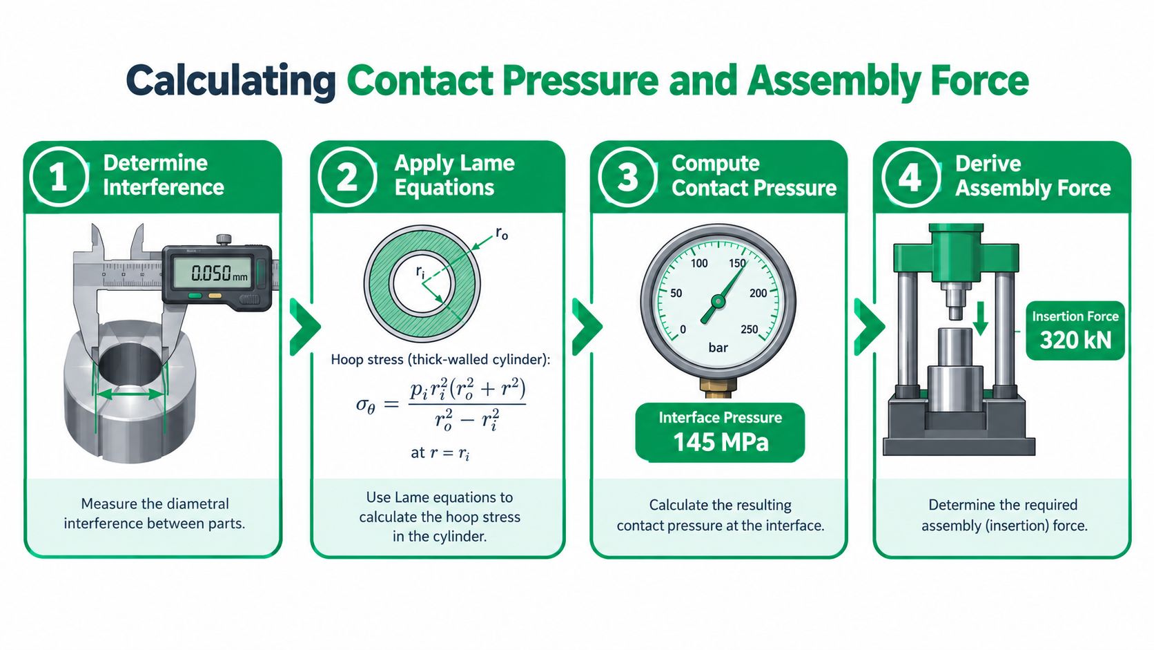
For a preliminary thick-walled-cylinder model, treat the hub as a cylinder loaded by internal pressure. The calculation requires the radial or diametral interference, the hole diameter, the hub outside diameter, the elastic modulus of the material system, the engagement length, and the friction coefficient at the interface. The press-fit calculator reference from Firgelliauto presents the same engineering workflow using Lame equations.
Start with the actual interference range
For each tolerance combination:
Diametral interference equals shaft outside diameter minus hole inside diameter.
If the result is positive, the shaft is larger than the bore. Convert that result to radial interference if the selected equation uses radial displacement. Keep units consistent throughout. A unit mismatch between millimetres and metres can overwhelm every other assumption in the calculation.
Then apply the geometry factor for the hub and shaft. A thick hub generally resists expansion more effectively than a thin-walled hub, so the same interference can produce a different interface pressure depending on the ratio between hub outside diameter and bore diameter. The shaft's stiffness also contributes to the shared elastic deformation.
The Lame-based relationship can be represented in general form as:
Contact pressure = interference ratio × elastic modulus × hub geometry factor
The exact geometry factor depends on the cylinder assumptions and whether the shaft's elastic response is included separately. For a production design, don't treat a simplified single-material expression as a final answer when the shaft and hub have substantially different stiffness or when either component approaches yield.
Translate pressure into assembly force
The axial force required to press the parts together is commonly estimated from:
Assembly force = π × interface diameter × engagement length × contact pressure × friction coefficient
This equation explains several shop-floor surprises. A longer engagement region increases the contact area and therefore increases the force needed to insert the shaft. A higher friction coefficient also raises insertion force, but it may improve static holding force. Lubrication can make assembly easier while changing the friction assumption that supported the original retention calculation.
Surface condition matters in both directions. Roughness can increase mechanical interaction and friction, but high asperities may flatten during assembly, alter the effective interference, or promote galling. A smooth, clean, compatible interface can reduce insertion force, but the design still needs enough normal pressure to resist the applied axial and torsional loads.
Separate retention from press capacity
Calculate the force at minimum and maximum interference, not only at the nominal condition. The minimum case tests whether the joint will slip. The maximum case tests whether the press, tooling, hub, shaft, and assembly operator can safely complete the operation.
A useful review includes:
- Interface pressure: Compare the predicted pressure with allowable stress and yield limits for both components.
- Axial insertion force: Check press capacity, tooling stiffness, and load alignment.
- Holding force: Estimate frictional resistance in the direction of service loading.
- Torque transfer: Convert the required torque into an equivalent circumferential force at the interface.
- Engagement length: Confirm that added length improves retention without creating an impractical press load.
- Failure mode: Check for hub cracking, shaft collapse, local yielding, galling, and partial seating.
The calculation is elastic only while the materials remain within their elastic range. Once local yielding or surface damage begins, the simple friction model no longer predicts the joint reliably. That's where a finite element model, material-specific allowables, or a physical trial becomes justified.
Know when statistical tolerance analysis belongs
Worst-case arithmetic is the correct first boundary. It tells you whether an impossible combination exists within the drawing limits. It doesn't tell you how often the production process will approach that boundary.
A statistical approach becomes useful when the process is stable and the team has enough inspection data to characterize shaft and bore distributions. Instead of assuming that every shaft reaches its largest limit while every hole reaches its smallest limit, the engineer models the combined variation and predicts the likely assembly population. This can prevent an unnecessarily narrow drawing tolerance and reduce avoidable rework.
Statistical analysis must still respect hard limits. If a tight fit can crack a thin housing, the maximum interference remains a hard ceiling. If a loose fit causes rotation or migration, the minimum interference remains a hard floor. Production distributions can guide process decisions between those boundaries, but they can't erase the boundaries.
Adjusting Interference for Material Pairs and Thermal Conditions
The same interference value doesn't produce the same joint across material combinations. Steel-on-steel, steel-in-aluminum, and steel-in-plastic assemblies have different stiffness, yield behavior, thermal expansion, surface response, and long-term stability. A fit that works in a rigid metal assembly may deform a softer housing or relax in a polymer component.
Material selection changes the pressure response. A stiffer component generally resists elastic deformation more strongly, while a lower-strength component may reach its allowable stress sooner. The engineer must check the shaft and hub separately, because the weaker part often controls the maximum usable interference.
Compare the material pair, not just the shaft
For a steel shaft in a steel hub, both components may share the elastic deformation in a relatively predictable way. The design still requires a check of hub wall thickness, local stress concentration, and assembly force, but a standard ISO fit can provide a useful starting point.
An aluminum hub changes the decision. Its lower stiffness and different yield behavior can make the housing more vulnerable to distortion, bore growth, or local damage during assembly. Increasing interference to compensate for thermal or vibration concerns may worsen the mechanical risk rather than improve retention.
Plastic and composite components require a different review again. Their response can include time-dependent creep, close-in around the bore, and changes in running clearance under temperature. The press-fit guidance for material-specific and thermal conditions reinforces the engineering point that there is no universal interference chart suitable for every material pair.
Material choice changes the allowable interference. It doesn't merely change the value entered for elastic modulus.
Evaluate temperature at both installation and service
Temperature changes the relative diameters of the shaft and hub. The change depends on each material's coefficient of thermal expansion and the temperature difference from the reference condition. If the shaft expands more than the hub during operation, the fit can tighten. If the hub expands more, the interface pressure can fall.
Designers should calculate the fit at the installation temperature and across the operating range. A cold assembly condition may create a different interference than a room-temperature inspection result. Heating the hub or cooling the shaft can ease assembly, but the final dimensions must be evaluated after both parts return to the intended service condition.
For dissimilar materials, thermal effects can dominate a small interference window. An aluminum housing around a steel shaft may respond very differently from a steel housing around the same shaft. In a polymer-metal assembly, thermal expansion and creep can combine, reducing retention over time or collapsing running clearance during operation.
Account for vibration and long-term loading
Static retention isn't enough for rotating, oscillating, or vibrating equipment. Cyclic loading can encourage fretting at a marginal interface, while thermal cycling can repeatedly change contact pressure. A polymer or composite component may also relax under sustained load, so an initially acceptable press fit may not maintain the same grip later.
The design review should document:
- Reference temperature: The temperature used for the dimensional calculation.
- Operating range: The cold and hot conditions that change relative size.
- Material properties: Elastic modulus, yield behavior, thermal expansion, and creep response where relevant.
- Service loading: Static force, torque, vibration, rotation, and fatigue exposure.
- Required condition: Retention, running clearance, alignment, or a combination of these.
For critical joints, use the thermal result to choose between a straight press fit, a shrink-fit process, a mechanical shoulder, a retaining compound, or a redesigned interface. More interference isn't automatically safer. A joint that depends on excessive pressure may lose reliability through yielding, fatigue damage, or permanent distortion.
Design for Manufacturability Rules for Precision Machined Fits
A correct equation won't rescue a part that is difficult to machine, inspect, or press together. Press-fit design must give the manufacturing team enough geometry to guide the shaft, enough access for tooling, and enough control over surface condition to preserve the intended interface.
The most reliable designs make the mating zone obvious. Keep the press surface free from interruptions, avoid unnecessary grooves in the contact region, and separate the functional bore from nearby features that can distort the housing during clamping or machining.
Give the assembly a controlled entry
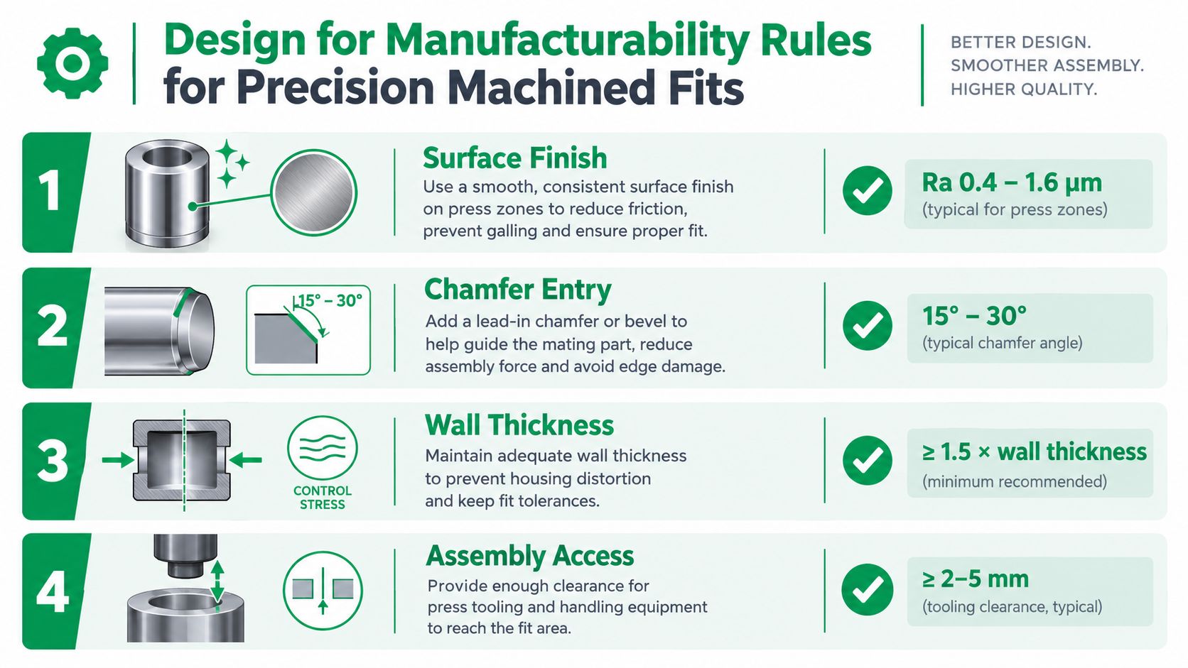
A lead-in chamfer helps the shaft start concentrically instead of scraping its edge across the bore. The chamfer must be large enough to remove the sharp corner and guide the parts, but it shouldn't consume the functional engagement length or create a weak edge on a thin wall.
Use a clean, consistent transition at the end of the press zone. Burrs, torn material, and a damaged entry edge can create a false high force at the start of insertion and may shave material into the joint.
Specify the press zone deliberately
Surface finish affects friction, galling, and the way asperities settle during assembly. Don't specify a decorative finish without identifying the functional requirement. The drawing should distinguish the press diameter from adjacent nonfunctional surfaces and should state any treatment that changes the effective size, such as plating, anodizing, coating, or conversion treatment.
Engagement length also needs a functional justification. More contact area can increase retention, but it can raise assembly force and make alignment more difficult. A long fit in a thin housing may also distort the bore instead of producing uniform pressure.
Shop-floor check: If the press tooling contacts a decorative face, a chamfer, or an unsupported wall, the assembly setup is already compromising the design.
Control location and coaxiality
A shaft can meet the diameter requirement and still assemble poorly if the hole axis is misaligned with the surrounding features. Use appropriate datums and geometric controls for coaxiality, position, perpendicularity, and runout where the application requires them. The right control depends on the function, so don't apply a tight geometric tolerance without identifying the datum relationship that matters.
Wall thickness deserves equal attention. A thin housing can ovalize under clamping or pressing, changing the bore condition from the one measured on a free part. Support the component near the press zone and design tooling that applies load along the intended axis.
For a broader look at process selection and tight-tolerance machining for press-fit features, connect the drawing requirements to the actual CNC, grinding, inspection, and finishing operations available. The supplier should know which dimensions are functional, which surfaces can float, and how the final finish changes the fit.
Plan the assembly operation with the part
Leave access for a flat, aligned press tool. Provide a shoulder or reference face where the shaft can stop at the correct seating depth. If the assembly requires heating, cooling, lubricant, or a controlled insertion speed, include those conditions in the work instruction rather than treating them as operator preference.
Design for inspection too. A bore that cannot accept a gauge, probe, or CMM stylus at the relevant locations creates uncertainty before the parts ever reach assembly. Manufacturing drawings should identify the inspection datums and the measurement condition, especially when coatings, temperature, or flexible materials affect the result.
Validating Your Press Fit Design Before Production
A calculation is a screening tool until a physical assembly confirms the assumptions. Before releasing a press fit to production, build representative parts using the intended material, machining process, surface treatment, and assembly method. A prototype made with a different finish or a relaxed tolerance may demonstrate appearance, but it won't validate the joint.
Start by measuring the parts individually. Record the shaft diameter at multiple axial and circumferential locations, then inspect the bore with a suitable gauge or coordinate measuring method. The CMM inspection service overview is relevant when the design depends on profile, position, coaxiality, or a tolerance stack that a basic hand gauge can't characterize.
Use a staged validation sequence
- Verify the dimensional stack. Confirm that the measured shaft and bore produce the intended interference, including form error and taper.
- Record assembly force. Monitor insertion force throughout the stroke, not just the peak. A sudden rise can indicate misalignment, burrs, galling, or a local geometric problem.
- Check seating and distortion. Measure the final position, bore condition, runout, and any visible cracking or permanent deformation.
- Test functional retention. Use push-out, pull-out, torque, or rotational slip testing that represents the actual service load.
- Cycle the environment. Expose the assembly to relevant thermal changes, vibration, and repeated loading before deciding that the fit is stable.
- Inspect after testing. Look for fretting, polished tracks, galling, migration, cracks, and changes in running clearance.
The test fixture must apply load through the same functional path as the product. A push-out test can verify axial retention, but it won't automatically validate torque transmission. Likewise, a room-temperature assembly test can't prove stability where dissimilar materials experience substantial thermal movement.
Move from prototype to controlled production
Use the prototype build to challenge the drawing, not to prove that every future batch will work. Review whether the parts can be measured consistently, whether the press force falls within equipment capacity, and whether operators can identify a partially seated assembly. If the measured interference varies widely, fix the process or revise the tolerance strategy before scaling.
For low-volume production, retain inspection records for the mating dimensions and assembly force. These records help separate a design problem from a machining problem when a joint fails. They also show whether the process is centered near the intended fit window or repeatedly approaches a dangerous limit.
A production release should include the fit designation, dimensional limits, relevant geometric controls, surface requirements, assembly tooling, lubrication or thermal instructions, seating requirement, and acceptance test. If any of those items remain implicit, the shop will fill the gap with an assumption.
The final engineering question is simple: does the joint remain within its acceptable mechanical window from the loosest manufactured condition through the tightest, hottest, coldest, and most heavily loaded condition? If the answer depends on a nominal diameter, the design review isn't finished.
FIRMFG supports CNC machining and precision prototype builds for metal and plastic press-fit components, including dimensional inspection and DFM feedback during design validation and low-volume production. If you're ready to test a tolerance stack with functional parts, visit FIRMFG and submit the shaft, bore, materials, operating conditions, and inspection requirements for review.