Slip Fit Tolerance: The Complete Guide
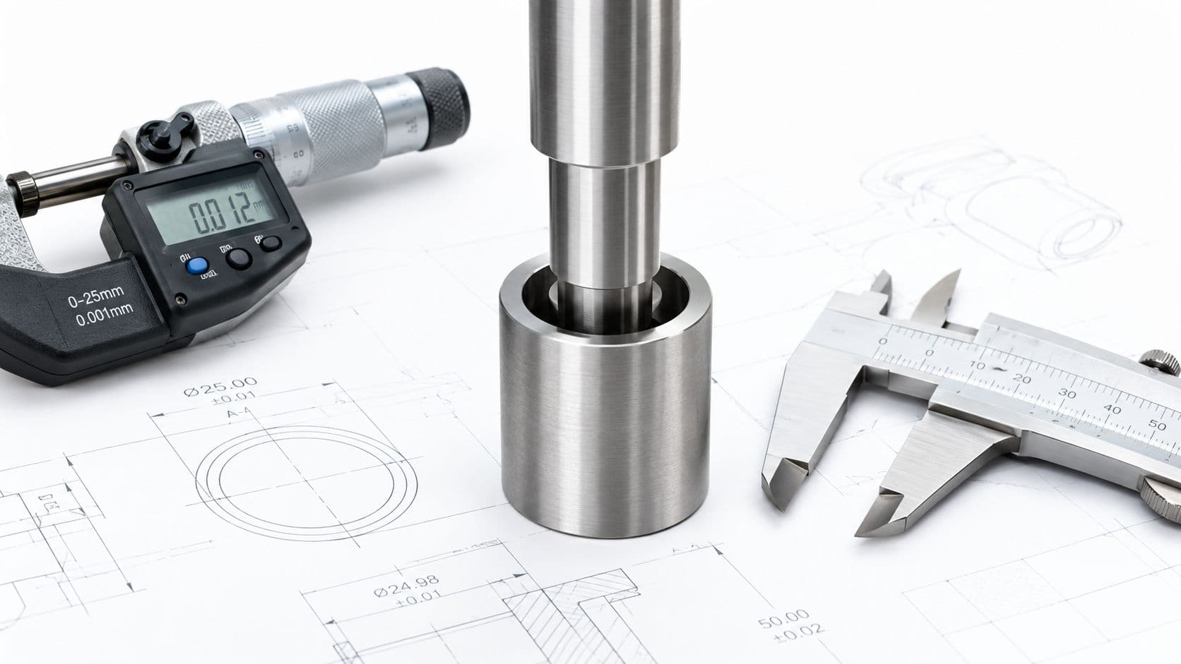
A shaft and bore can both pass dimensional inspection and still refuse to assemble on the bench. Usually, the problem isn't the nominal diameter. It's the relationship between the smallest possible bore, the largest possible shaft, surface condition, geometry, temperature, and the manufacturing process used to produce each part.
That relationship is slip fit tolerance. A good specification gives the shaft guaranteed positive clearance, so it enters by hand, while keeping movement controlled enough for alignment, rotation, or sliding service. A poor specification either binds unpredictably or leaves so much play that the assembly rattles, wears, or loses position. The practical target isn't the tightest fit available. It's the loosest fit that still performs its job consistently and can be manufactured without turning every batch into a sorting exercise.
Table of Contents
How Slip Fit Tolerance Works and What Standards Apply- Reading the designation
Choosing the Right Slip Fit Class for Your Application- Trade-offs that matter on the shop floor
Design for Manufacturing Achieving Slip Fits Across Processes- CNC machining
Critical Factors That Affect Slip Fit Performance- Temperature belongs in the tolerance calculation
Inspection and Quality Assurance for Slip Fit Tolerances- Match the gauge to the risk
Putting It All Together A Slip Fit Design Checklist
Understanding Slip Fit Tolerance in Manufacturing
A drawing that specifies only a “25 mm shaft” and “25 mm hole” leaves assembly to chance. Both parts may measure close to nominal, yet the shaft can drag at the entrance, stop partway through, or fit easily while leaving excessive wobble. The failure comes from controlling each dimension separately instead of defining the clearance between the mating surfaces.
A slip fit requires controlled positive clearance. The shaft must remain smaller than the bore across the full permissible tolerance range. That condition distinguishes a clearance fit from a transition fit, where some in-tolerance combinations assemble freely and others need force. Published machining guidance on slip-fit tolerances describes slip fits as precision assembly conditions rather than loose, unregulated connections.
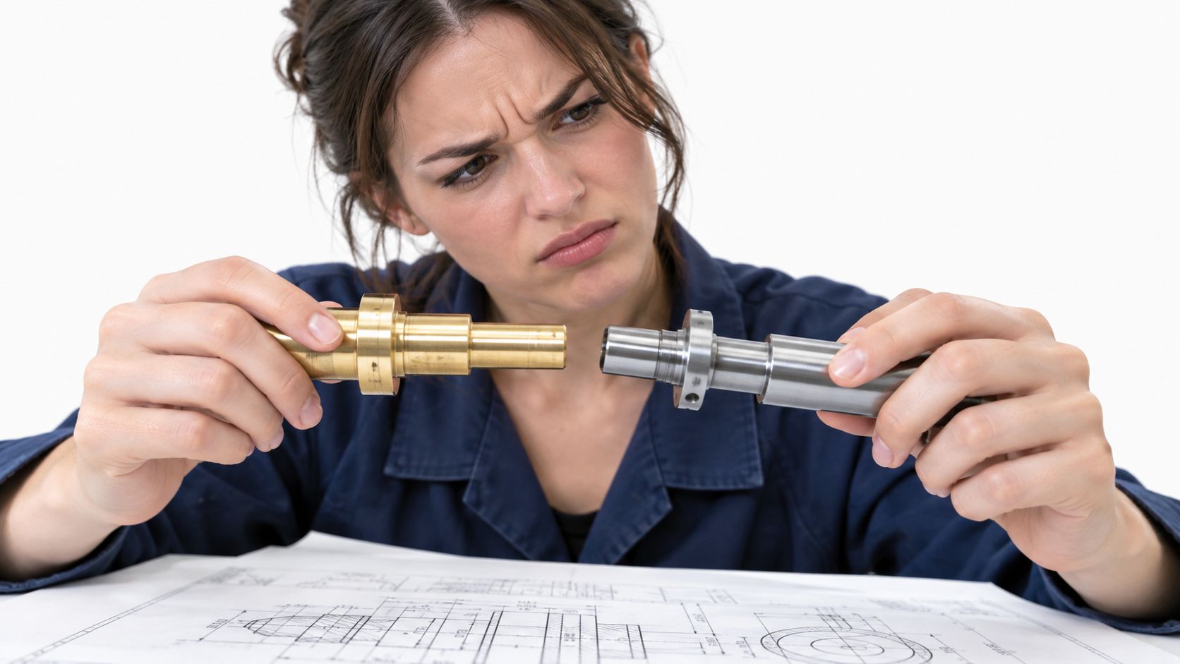
The required clearance follows the assembly's job. A removable locating pin needs easy insertion while preserving repeatable position. A sliding guide needs room for movement, lubrication, and temperature change. A rotating shaft needs enough clearance to move smoothly without creating unacceptable runout. One nominal diameter can therefore require different fit classes, tolerance limits, and inspection methods.
Why the process changes the answer
CNC turning, boring, reaming, and grinding can all produce mating features, but they do not offer the same capability or cost. Bores often require closer process control because tool deflection, chip evacuation, taper, and alignment can change the result along the feature. Measuring one location may miss a problem that prevents assembly.
Injection-molded parts bring contraction, mold wear, parting-line effects, and cooling variation. Additive manufacturing adds shrinkage, build orientation, layer texture, and post-processing requirements. Sheet metal features usually need another approach, such as formed geometry, machined inserts, or controlled alignment holes, rather than treating a punched opening like a precision bore.
Practical rule: Define the required assembly behavior first. Then select a tolerance class, production process, and inspection method that can deliver it repeatedly.
A cost-effective slip fit aligns design intent with actual process capability. If the tolerance is tighter than the process can hold, scrap and sorting replace reliable assembly. If it is looser than the function allows, the parts may assemble easily but fail through play, wear, or poor alignment.
How Slip Fit Tolerance Works and What Standards Apply
A slip fit succeeds only when the shaft and bore limits are specified as a pair. The ISO fit system expresses that relationship with designations such as H7/g6. The letter identifies the tolerance-zone position relative to the nominal dimension, while the number identifies the IT grade, or tolerance-band width. A lower grade such as IT6 permits less variation than IT7 or IT8. ISO 286 provides the metric framework for these fits.
Hole designations use uppercase letters, and shaft designations use lowercase letters. In a hole-basis system, an H hole starts at nominal size and extends above it. A g shaft lies below nominal, so the combination creates clearance when both features remain within their specified limits.
A published manufacturing example gives IT6 tolerance on a 25 mm feature as 0.013 mm in its discussion of slip-fit tolerances. That scale affects process selection. A simple-looking drawing may require micron-level control, and the bore and shaft tolerances combine at their worst-case limits.
Reading the designation
| Designation element | What it controls | Practical meaning |
|---|---|---|
| Uppercase letter | Hole tolerance-zone position | Sets the bore limits relative to nominal |
| Lowercase letter | Shaft tolerance-zone position | Sets the shaft limits relative to nominal |
| IT number | Tolerance-band width | Sets the permitted dimensional variation |
For common H7/g6 sizes, published ISO examples show 18 to 30 mm fits with 9 to 46 µm clearance, and 30 to 50 mm fits with 11 to 55 µm clearance, as shown in this guide to CNC machining tolerances and fit specification. These ranges demonstrate why a slip fit is more than a hole slightly larger than a shaft. The clearance window must meet the assembly function while staying within the selected process capability.
ASME and ANSI fit classifications use different naming conventions for inch-based drawings, while ISO 286 is the usual reference for metric fits. The engineering work remains consistent: select the fit class, calculate minimum and maximum clearance, and confirm that the limits support assembly and operation. A tighter class may improve alignment but increase machining, inspection, and scrap risk. A looser class may reduce cost but allow unacceptable play.
Do not place only H7 on a drawing and leave the shaft undefined. A hole tolerance alone cannot establish the mating fit. Specify limits for both features or use a recognized hole-and-shaft designation.
Choosing the Right Slip Fit Class for Your Application
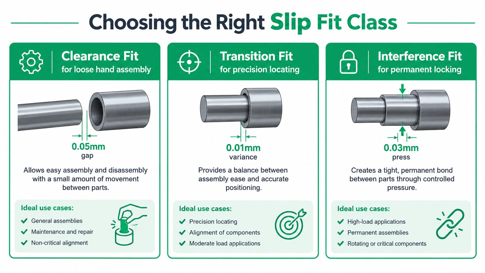
A shaft that should slide freely can seize during assembly, while a locating pin with excessive clearance can shift under load. Choose the fit from the assembly's actual job, then check whether the selected process can produce it consistently. A locating feature prioritizes positional control. A sliding sleeve needs freedom of movement. A low-speed plain bearing may require additional room for lubrication, contamination, surface variation, or thermal change.
The practical comparison often centers on H7/g6 and H8/f7. H7/g6 gives a tighter fit for precision rotation, locating features, and controlled alignment. H8/f7 provides more clearance and better tolerance of lubrication changes, surface imperfections, and freer sliding. For low-speed plain-bearing or oscillating applications, H7/f7 can provide useful additional clearance, while H7/g6 remains suitable when alignment requires closer control, as explained in this fit-selection reference.
| Application priority | More suitable direction | Why |
|---|---|---|
| Accurate locating with removable assembly | H7/g6 or a tighter validated class | Limits positional play while preserving positive clearance |
| General precision rotation | H7/g6 | Balances alignment, motion, and manufacturability |
| Freer sliding under variable conditions | H8/f7 | Provides more room for lubrication and surface variation |
| Low-speed plain bearing or oscillating motion | H7/f7 | Accommodates lubrication and operating variation |
| Loose, non-precision movement | A more generous clearance class | Avoids binding when location accuracy is secondary |
Trade-offs that matter on the shop floor
A tighter class can improve location, but it also makes tool wear, thermal drift, burrs, taper, and measurement variation more likely to affect assembly. A looser class simplifies production and assembly, yet may introduce noise, vibration, or alignment error. Select clearance from the operating load and motion rather than trying to eliminate every visible gap.
Multiple locating features require a tolerance review before release. A shaft may fit each bore separately and still bind when several bores are assembled together. Use tolerance stack analysis for mating features when alignment depends on more than one hole-and-shaft pair.
The cost-effective specification is usually the least restrictive class that still protects function. If the assembly tolerates more clearance, choose a class the selected process can hold without extensive sorting. If play is unacceptable, tighten the fit deliberately and allow for the finishing and inspection work needed to repeat it. This approach connects fit performance to manufacturability before parts reach the shop floor.
Design for Manufacturing Achieving Slip Fits Across Processes
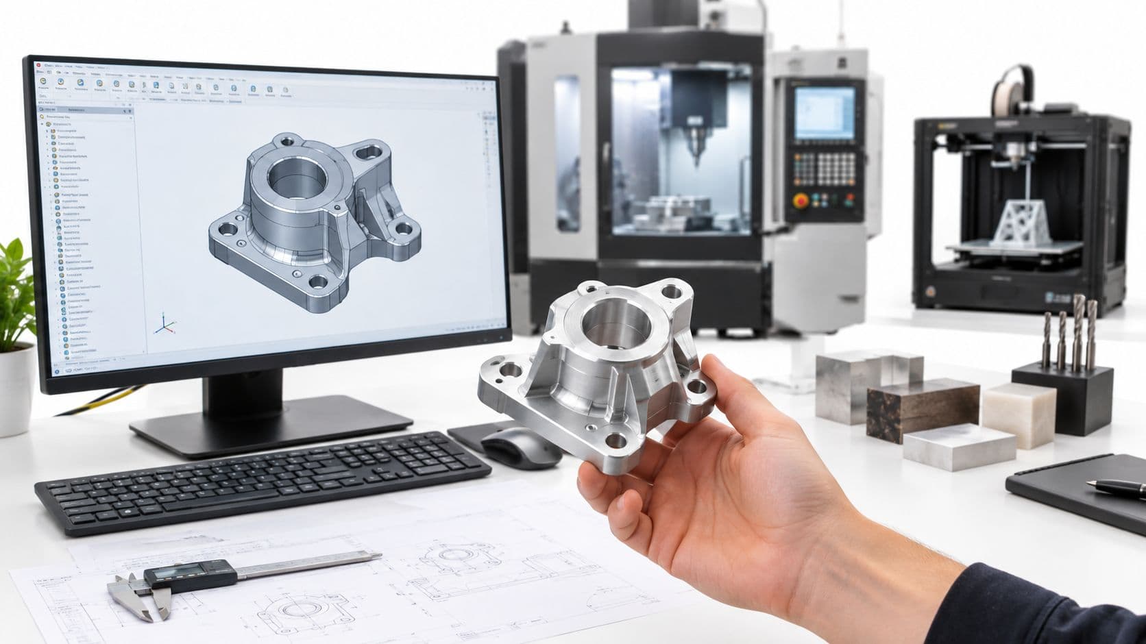
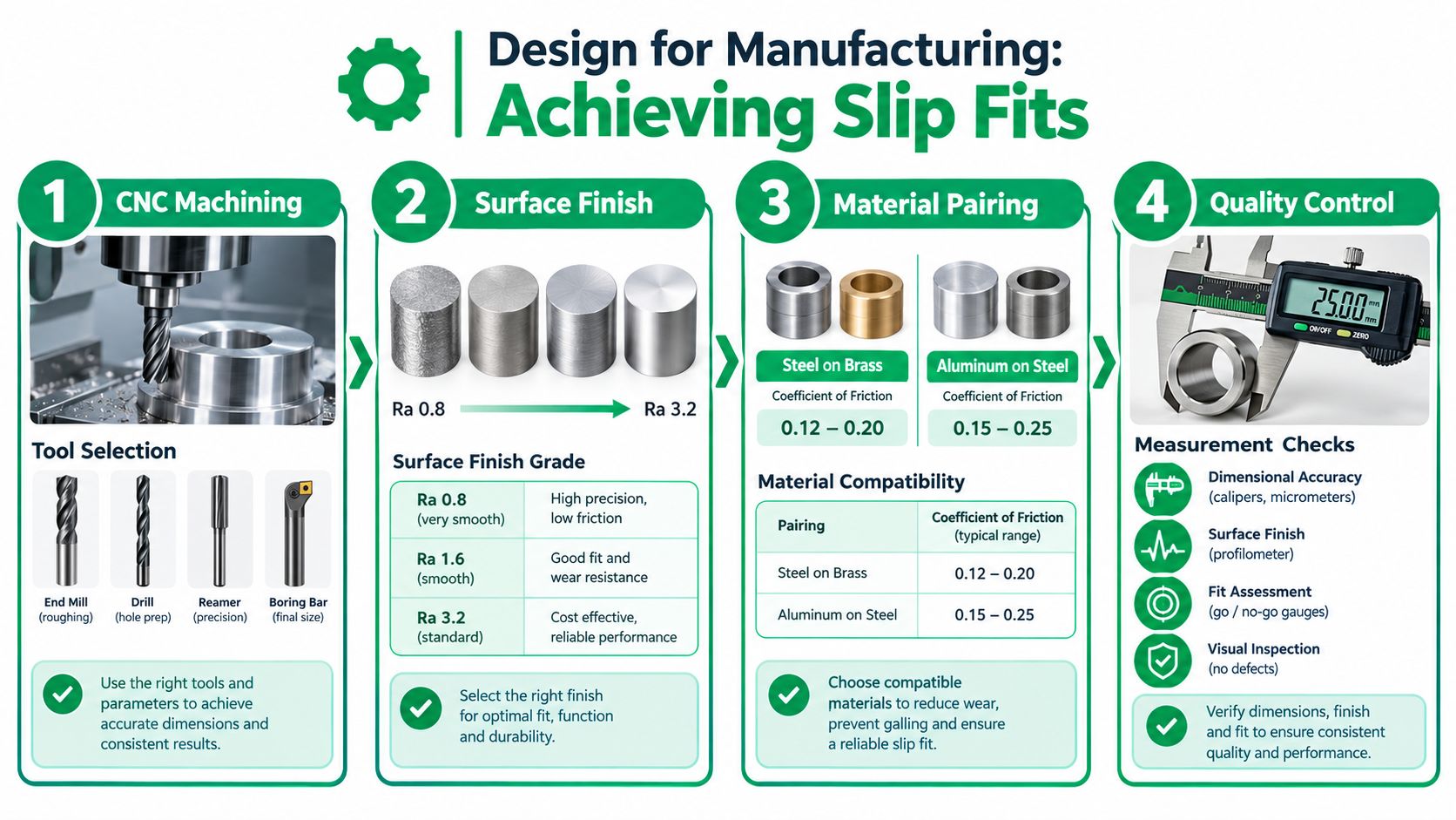
A slip fit should be designed together with its production route. The same clearance target may be realistic for a turned steel shaft and difficult for a molded polymer bore. Start by identifying the critical mating surfaces, then ask how the chosen process controls size, roundness, straightness, surface texture, and post-process growth.
CNC machining
For CNC parts, separate roughing from finishing. Leave a controlled finishing allowance for boring or reaming, and use turning, grinding, or another suitable finishing method for the shaft when the fit window is narrow. Inspect the bore at multiple locations, because diameter alone won't reveal taper or out-of-roundness.
Tool selection matters. A stable boring setup reduces deflection, while a properly prepared reamer can improve repeatability for suitable production volumes. On the shaft, a controlled turning operation may be sufficient for a practical fit, but tighter requirements can justify grinding after heat treatment or another finishing operation.
Injection molding
Molded slip-fit features need draft, cooling, material shrinkage, and mold wear considered from the beginning. Don't copy a machined H7/g6 assumption directly into a molded bore and expect equivalent behavior. Use design features that protect the mating surface, validate the actual molded dimensions, and reserve machining or an insert for critical locations when the polymer process can't hold the required relationship consistently.
Additive manufacturing
Printed mating parts often need clearance allowances that reflect material, orientation, layer geometry, and post-processing. A vertical bore, a horizontal bore, and a bore opened by drilling won't necessarily behave the same way. For functional prototypes, print a fit coupon using the intended material and orientation, then measure and adjust the production geometry before committing to the full assembly.
Sheet metal and hybrid assemblies
Sheet metal is rarely the right place to demand a precision sliding bore directly from a punched or laser-cut feature. Use a machined bushing, pressed insert, or secondary boring operation when alignment matters. For formed assemblies, control the relationship between holes through the setup and joining sequence, not just the size of each individual hole.
Cost control starts with process selection. A generous fit made with a stable process is usually cheaper than an unnecessarily tight fit that requires repeated adjustment, special gauging, and part sorting.
For every process, specify the finish condition that affects the final fit. Coatings, deburring, blasting, anodizing, plating, and paint can consume clearance, so the inspection plan must identify whether dimensions apply before or after finishing.
Critical Factors That Affect Slip Fit Performance
A part can pass a diameter check and still fail in assembly. Surface peaks, burrs, taper, material movement, and temperature reduce the clearance that actually supports sliding. Specify and control these factors together, especially when selecting a process for production.
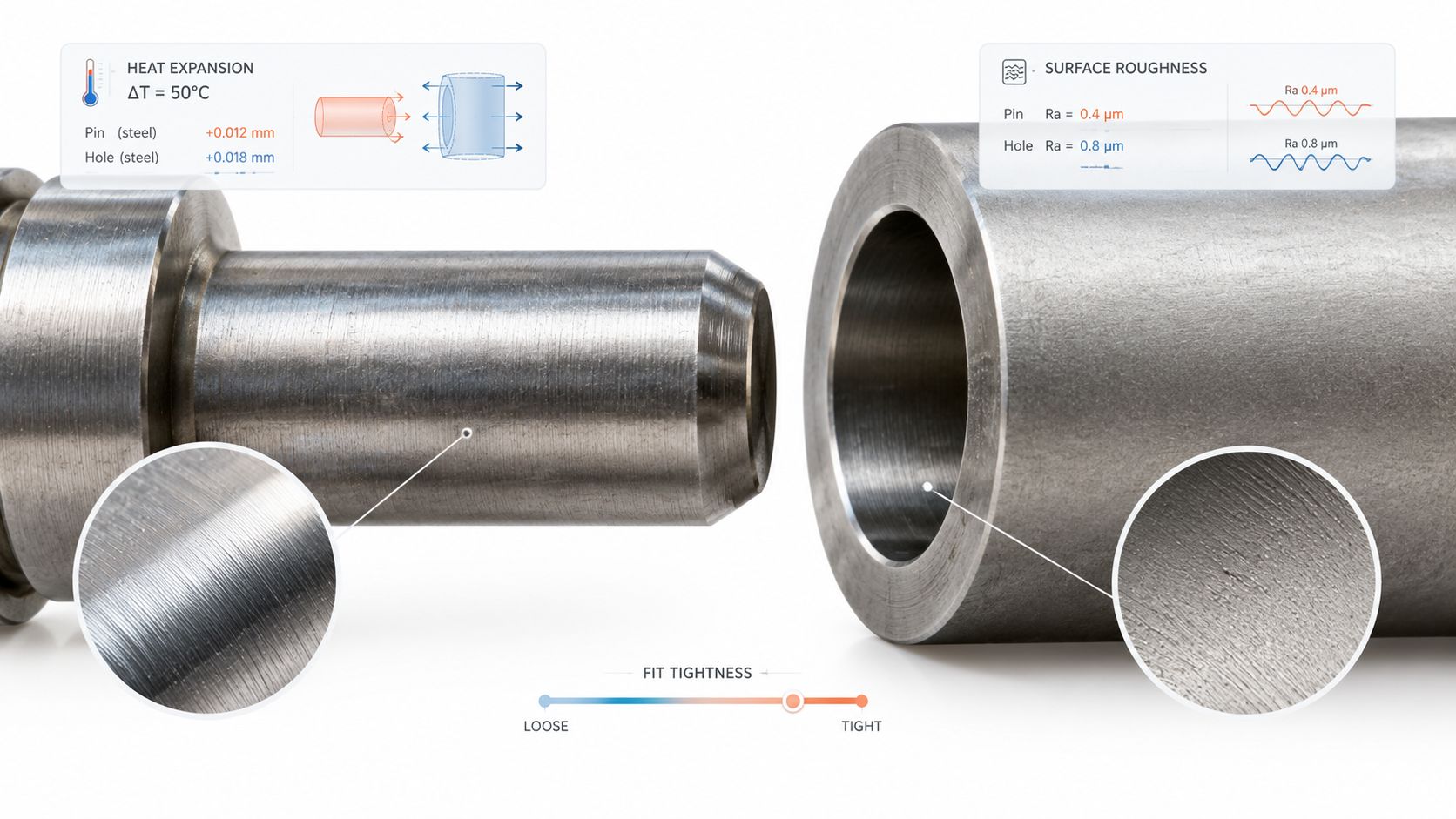
Surface finish affects insertion force and running friction because rough peaks occupy part of the nominal gap. A bore and shaft may both fall within their size limits yet feel tight if their texture is coarse or inconsistent. Deburring matters at the entry as well as along the feature. A small burr can make a sound fit appear undersized and score the mating surface during installation.
Material pairing determines how the fit behaves after repeated motion. A hard shaft against a softer bearing material may resist wear better than two similar materials that tend to seize. Select the pair according to lubrication, contact pressure, duty cycle, and contamination. Availability alone is a poor basis for the choice.
Temperature belongs in the tolerance calculation
The minimum clearance must exceed both combined manufacturing tolerance and expected differential thermal growth. Check the fit at assembly temperature and at the full operating range. A shaft that slides freely during inspection can tighten in service if it expands more than the bore.
Different materials make this calculation more important. Aluminum and steel respond differently to temperature, so clearance can increase or decrease according to which material forms the shaft and which forms the bore. For assemblies exposed to a broad temperature range, calculate the worst-case condition rather than accepting room-temperature feel as proof of performance.
Geometry and assembly technique
Control cylindricity, straightness, and concentricity when the parts must align over a meaningful length. A bore can meet its diameter requirement at both ends and still bind because of taper, local distortion, or a bowed feature. Thin walls may deform after clamping or fastening, changing the fit after inspection.
Assembly practice must match the drawing intent. Use clean, deburred parts, the specified lubricant, and the intended orientation. Do not apply force to prove a slip fit. If the part needs tapping, heating, or repeated rocking, stop and check clearance, surface condition, and alignment before accepting the assembly. That investigation is cheaper than sorting finished units or repairing damaged mating surfaces.
Inspection and Quality Assurance for Slip Fit Tolerances
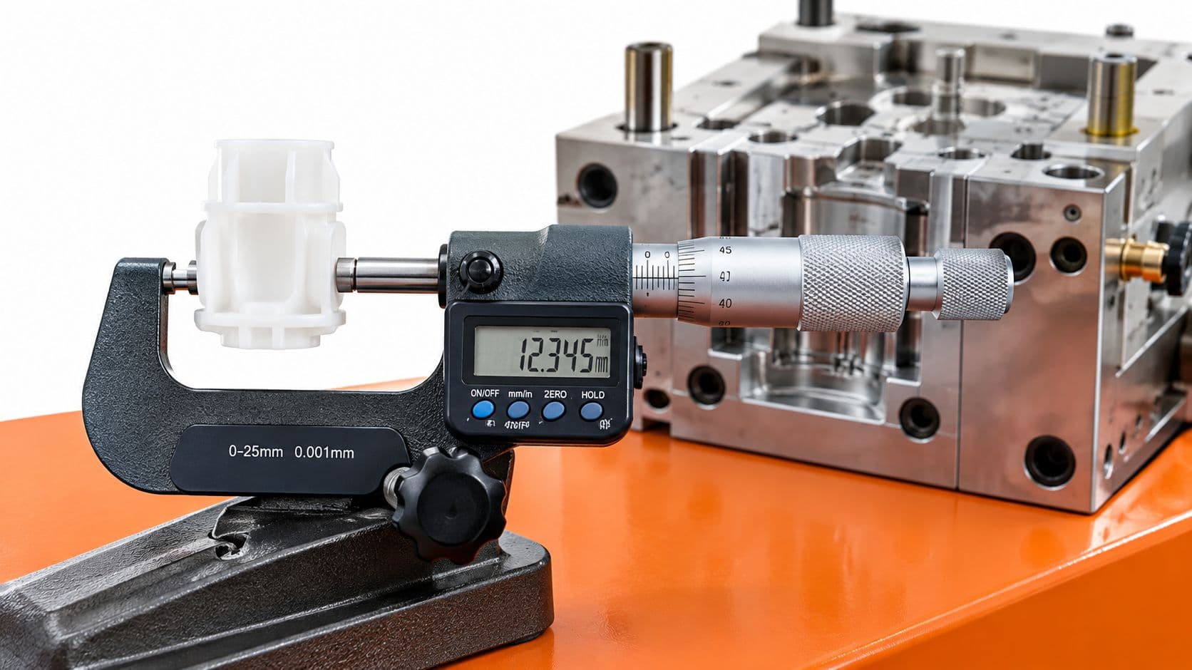
Inspection should verify the mating relationship, not just two independent diameter readings. For a prototype, a calibrated micrometer can check a shaft and a suitable bore gauge can check the hole. Calipers are useful for rough checks, but they're not an appropriate final method for a tight slip fit because contact pressure, resolution, and operator technique can obscure the available clearance.
Measure the parts at a controlled temperature and inspect more than one location along the feature. Check for taper, out-of-roundness, burrs, and visible tool marks. If the fit is important to motion or alignment, record the actual shaft and bore values rather than marking only pass or fail.
Match the gauge to the risk
A functional plug gauge can quickly confirm whether a bore accepts the intended mating condition. Ring gauges can provide a comparable check for shafts. These methods are fast, but they don't replace dimensional analysis when the design depends on a narrow clearance window or when the assembly contains multiple interacting features.
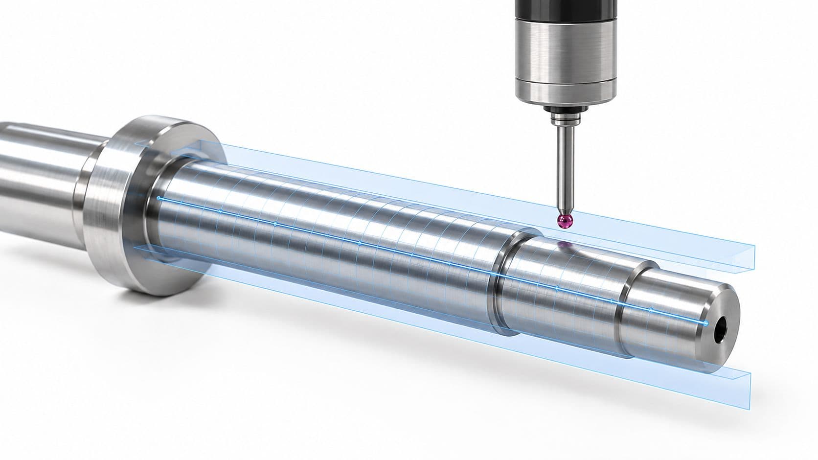
For prototypes and low-volume work, a CMM can verify diameter, position, form, and alignment in one inspection routine. CMM inspection services for dimensional verification are useful when a simple hand measurement can't explain why individually acceptable parts bind in the assembled condition.
Put the acceptance criteria on the drawing
State the hole and shaft limits, material condition, surface-finish requirement, datum structure, and whether dimensions apply before or after coating. Identify critical features and request inspection records for them. If a contract manufacturer supplies a first-article report, make sure it includes the actual measured values and the equipment or method used.
During production, monitor drift instead of waiting for failed assemblies. Tool wear, thermal changes, and setup movement can shift a process gradually. A stable measurement routine lets the manufacturer adjust offsets before the clearance window closes.
The final test should still be functional assembly. A part can satisfy a dimensional report and fail because the mating axes are misaligned, the bore is tapered, or a burr remains at the entrance.
Putting It All Together A Slip Fit Design Checklist
Use this checklist before releasing a drawing or sending a prototype to production:
- Define the function: Decide whether the joint must rotate, slide, locate, or assemble and disassemble.
- Set the clearance window: Calculate minimum and maximum clearance from the actual hole and shaft limits, not from nominal sizes.
- Choose the fit class: Use H7/g6 for a tighter precision compromise, H8/f7 for freer sliding, or another recognized class that matches the application.
- Check operating temperature: Confirm that differential thermal growth won't consume the minimum clearance.
- Review material pairing: Consider galling, wear, lubrication, hardness, and the direction of material expansion.
- Specify geometry: Add the form and alignment controls needed to prevent taper, lobing, runout, or multi-bore binding.
- Select the process: Use turning, boring, reaming, grinding, molding, printing, or a hybrid process according to demonstrated capability.
- Account for finishing: Include anodizing, plating, paint, deburring, and other treatments in the final dimensional condition.
- Plan inspection: Identify the measurement method, locations, temperature condition, functional gauges, and required documentation.
- Test the assembly: Verify insertion force, sliding or rotational behavior, alignment, and performance at the intended operating condition.
The best slip fit tolerance is the one that works across the full tolerance stack and remains practical for the shop producing it. If the specification requires constant hand selection, the design is too tight, the process is unstable, or the inspection plan is incomplete.
FIRMFG supports CNC machining, additive manufacturing, sheet metal, molding, finishing, and inspection for prototypes and low-volume parts, with technical feedback on mating surfaces and alignment features. To reduce assembly risk before production, send your drawings and fit requirements to FIRMFG for a manufacturability review and quote.