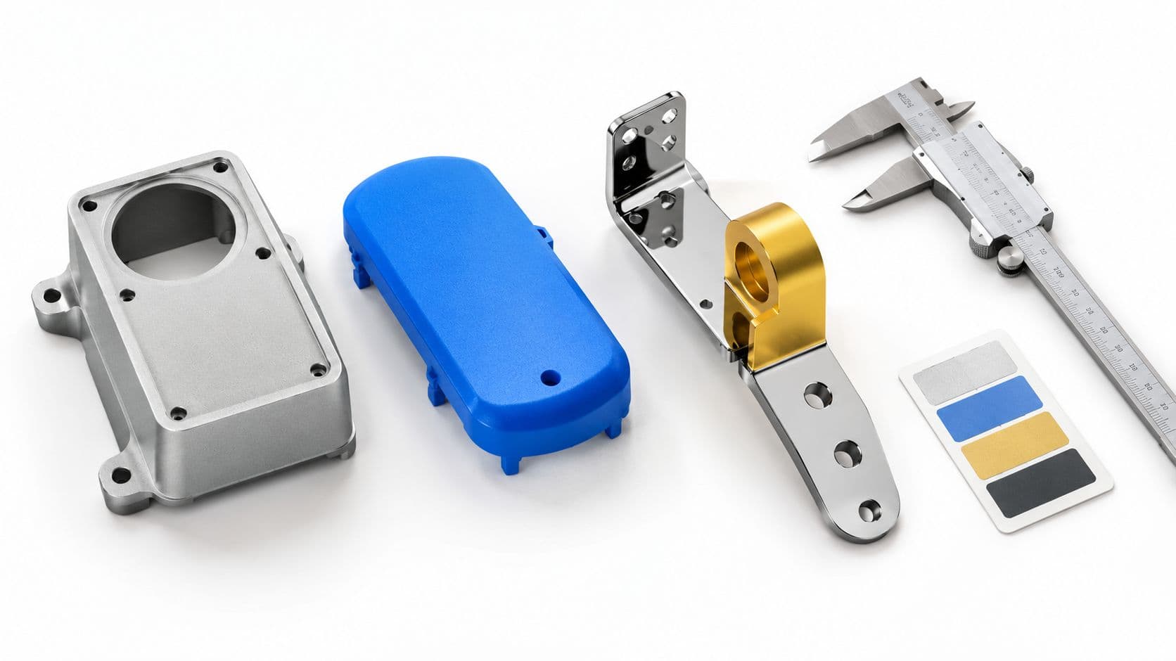
Rapid Prototyping Definition, Methods, and Practical Use
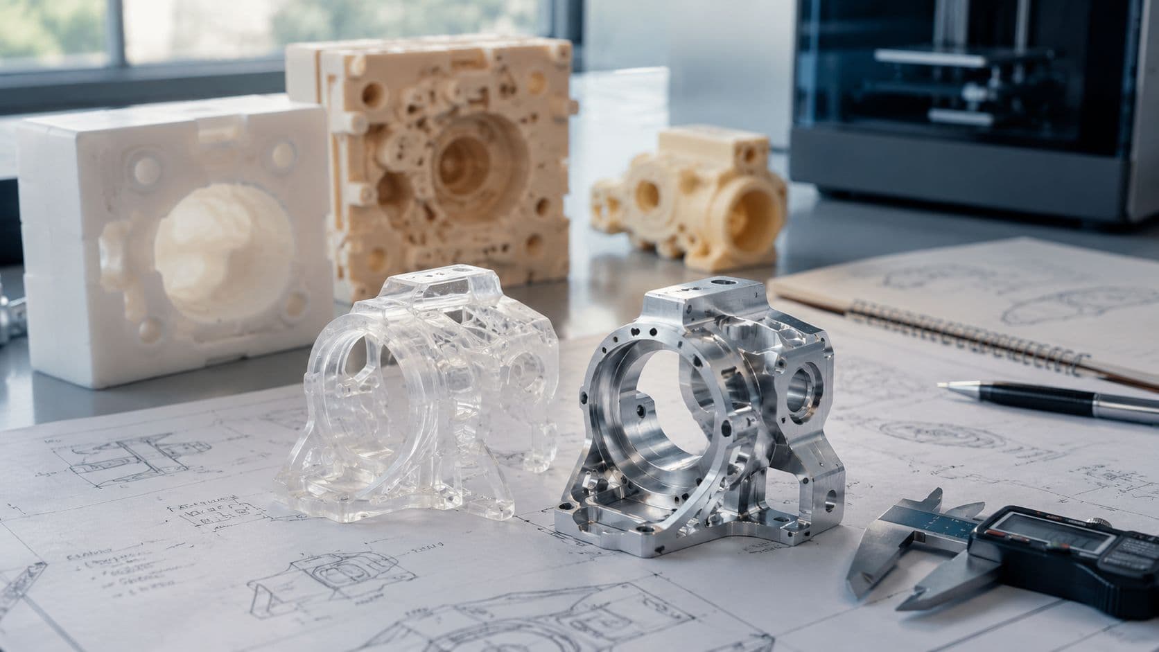
A handheld consumer device is approaching three design reviews in twelve weeks. Marketing needs a convincing hero unit, the test lab needs something it can assemble and operate, and production tooling cannot justify another untested design change. The question isn't, “Which machine can make the part fastest?” It's, “What must this prototype prove before the next decision?”
That question leads to a practical rapid prototyping definition. Rapid prototyping is the fast, iterative production of physical parts from digital designs so engineers can validate form, fit, function, and manufacturability before committing to production tooling. The method may involve additive manufacturing, CNC machining, casting, injection molding, or a combination of processes. The defining feature is the shortened learning loop, not the machine category.
Table of Contents
How Rapid Prototyping Evolved from 1987 to 2026- From one process to a process family
Core Methods Compared Side by Side- Rapid Prototyping Methods at a Glance
Typical Timelines and Cost Ranges- Typical Timelines and Cost Ranges by Rapid Prototyping Method
DFM Tips That Save Time on Every Method- CNC and SLA decisions
Choosing the Right Method by Intent and Industry- Form and fit
Bridging Prototypes to Low-Volume Production- Signals that the handoff will work
Rapid Prototyping Questions Engineers Ask Most- Is rapid prototyping the same as 3D printing?
- Does rapid prototyping include CNC machining?
- When should a team skip direct prototyping and use rapid tooling?
- What tolerances should I expect?
- What should I send for a quote?
What Rapid Prototyping Means in Modern Manufacturing
A prototype is valuable only when it answers a question. A housing may need to prove that a user can hold it comfortably. A bracket may need to prove that it fits around a mating component. A latch may need to survive repeated operation. One physical part rarely answers all three questions equally well.
Independent manufacturing guidance describes rapid prototyping as a workflow that converts CAD concepts into physical test parts, then uses those parts to validate form, fit, and function before production tooling is approved. The process works because teams can build, inspect, test, revise the CAD model, and produce another version without treating the first prototype as a finished design. Formlabs' guide to rapid prototyping explains this iterative role and the way each build can expose dimensional mismatch, assembly interference, ergonomic problems, or material limitations.
Three prototype intents
The most useful way to classify a prototype is by what you need to learn from it.
- Form and fit models show appearance, scale, ergonomics, packaging, and assembly relationships. An SLA enclosure with a smooth surface may be ideal for a design review, even if its resin doesn't represent the final production plastic.
- Works-like prototypes reproduce a mechanism or use case with substitute materials. An SLS nylon snap-fit, a CNC-machined engineering plastic lever, or a short-run molded part can reveal whether the design operates as intended.
- Production-representative units are built to reflect final material, process behavior, surface treatment, and inspection requirements. Rapid tooling or CNC machining in the intended production material may be necessary when certification, customer sampling, or process validation depends on realistic behavior.
Practical rule: Choose the prototype around the next decision, not around the equipment already available.
Rapid prototyping also supports more than engineering validation. Teams use physical parts for usability testing, stakeholder alignment, vendor qualification, material screening, and fundraising demonstrations. A CAD model can communicate intent, but a physical unit reveals hand feel, access, interference, visible gaps, and assembly sequence.
The approach emerged as a way to create physical models directly from CAD data, with early methods becoming available in mid-1987. The history of rapid prototyping shows why the term still matters. It marks the move from labor-intensive manual model making toward digitally driven, layer-based fabrication. Today, the definition has broadened into a lifecycle capability, where the right process changes as the product moves from concept to functional validation and low-volume production.
How Rapid Prototyping Evolved from 1987 to 2026
A designer can now send CAD data to a supplier and review a physical part before production tooling exists. That workflow grew from stereolithography. In the 1980s, engineers needed a faster way to turn digital shapes into physical models for design review and early functional checks. Hideo Kodama's work and Charles Hull's development of stereolithography are widely associated with the foundations of modern rapid prototyping. The first methods became available in mid-1987, as recorded in the historical overview of rapid prototyping.
The early benefit was shorter learning cycles. Before digital fabrication, conceptual models and functional prototypes could take months and cost thousands of dollars. Stereolithography created parts directly from digital geometry, so designers could inspect form, fit, and selected features before committing to production tooling.
From one process to a process family
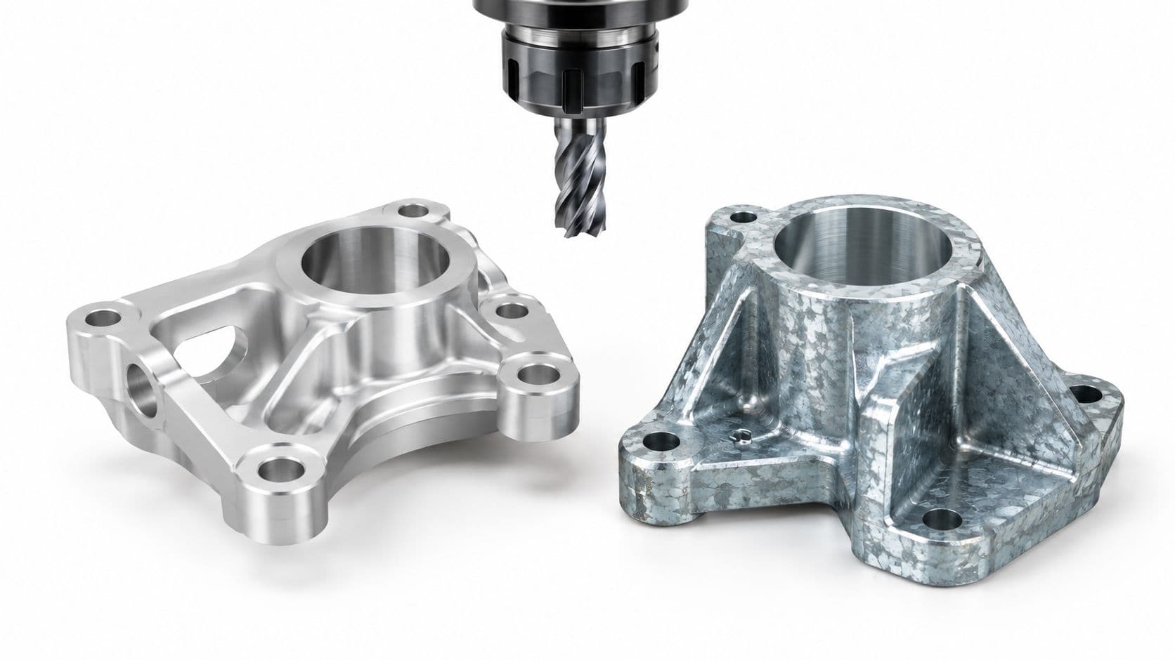
The field expanded as engineers matched different processes to different decisions. Powder-based systems made durable polymer parts possible without the same support requirements as resin printing. Fused-filament systems broadened access to thermoplastic prototypes. CNC machining added a subtractive route for metal parts, production-grade plastics, and situations requiring tighter dimensional control.
Casting and soft tooling connected one-off prototypes with small-batch output. An SLA or CNC master could produce a silicone mold and polyurethane replicas. Temporary injection molds could also provide molded samples before hardened production tooling justified its cost.
By the 2020s, rapid prototyping meant more than producing an early visual model. It covered additive, subtractive, formative, and hybrid workflows, with method selection tied to intent. Choose a detail-focused process for form and appearance, a machined or durable polymer part for works-like testing, and casting or rapid tooling when the prototype must resemble production behavior. Recent coverage of rapid prototyping in 2026 describes this broader lifecycle framing. An engineering review of technologies and materials also emphasizes material limits, equipment reliability, skills, and certification requirements.
Market estimates show the field's expansion, although their scopes differ. One 2026 estimate values the global market at USD 4.83 billion and projects USD 24.71 billion by 2035, with a 19.94% CAGR. The market estimates and their scope differences are discussed here. Another report estimates USD 15.2 billion in 2024 and projects USD 34.8 billion by 2034, at an 8.6% CAGR, using a different market definition. The practical conclusion is consistent: CAD-linked fabrication, additive manufacturing, and faster product development now support a path from concept validation toward low-volume production.
Core Methods Compared Side by Side
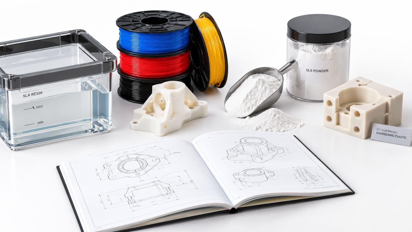
Method selection becomes clearer when you compare processes against the actual engineering decision. CNC machining removes material from a solid block, so it can provide metal or engineering-plastic behavior that printed resin may not reproduce. SLA prioritizes detail and surface quality. SLS offers durable nylon geometry without conventional support structures. Vacuum casting creates several polyurethane replicas from a master. Rapid tooling moves closer to injection-molded behavior and repeatable small-batch output.
The table below uses practical bands rather than promises. Actual results depend on geometry, supplier capability, inspection requirements, and the drawing revision.
Rapid Prototyping Methods at a Glance
| Method | Typical Tolerances | Common Materials | Lead Time | Best Fit Intent |
|---|---|---|---|---|
| CNC machining | Tightest control among these methods when geometry and fixturing permit | Aluminum, steels, engineering plastics | Short for stable, accessible parts, longer when setups are complex | Works-like testing, tight fits, production-material validation |
| SLA | Good detail and dimensional control, with resin behavior influencing final performance | Photopolymer resins | Very short for small parts, plus support removal and curing | Form, appearance, fine features, masters, jigs |
| SLS | Suitable for functional polymer parts, with surface texture influenced by powder processing | Nylon powders, including nylon 12 | Short build cycle, followed by depowdering and finishing | Works-like housings, snap fits, complex assemblies |
| Vacuum casting | Depends on master quality, mold design, resin choice, and shrinkage control | Polyurethane resins | Mold preparation adds time, followed by repeat casting cycles | Appearance models, beta units, small batches |
| Rapid tooling | Near-production behavior depends on mold material, resin, cooling, and process control | Aluminum or soft-steel molds, production thermoplastics | Longer than direct printing or machining because tooling must be designed and built | Production-representative parts and bridge builds |
CNC is often the right choice when the fit between components matters more than the speed of the first visual review. Engineers comparing additive and subtractive options can use this CNC machining versus 3D printing comparison to examine how material, accuracy, geometry, and setup affect the decision.
SLA works well for a polished enclosure review or a master for casting, but many photopolymer resins have limited mechanical strength and can age under ultraviolet exposure. SLS nylon is better suited to functional polymer geometry, especially when designers need snap features or complex shapes without support structures, though its surface is generally rougher.
Vacuum casting makes sense after the design has stabilized enough to justify a master and silicone mold. Rapid tooling requires an even stronger commitment, but it can provide a meaningful handoff to injection molding when material behavior and production process are part of the validation question.
Typical Timelines and Cost Ranges
A flat price list rarely helps an engineer estimate a prototype accurately. Part size, tolerance stack, surface finish, batch quantity, material availability, fixture complexity, and post-processing usually move the quote more than the label of the process itself.
For a small CNC order, programming and fixturing can dominate the first part cost. Aluminum may machine efficiently, while a difficult orientation, deep cavity, or multiple setups can add substantial work. SLA pricing usually follows build volume, support structure, resin, and finishing labor. SLS economics depend on build utilization, powder handling, and the amount of cleaning or surface treatment required.
Vacuum casting has a different cost curve. The silicone mold creates an initial charge, then the process becomes more attractive as the batch grows. Rapid tooling takes longer at the start because the mold must be designed, machined, finished, and tested, but the per-part economics improve once the tool produces a meaningful run.
Typical Timelines and Cost Ranges by Rapid Prototyping Method
| Method | Typical Lead Time | Practical Batch Size | Main Cost Drivers |
|---|---|---|---|
| CNC machining | Often three to seven business days for one to five parts, depending on complexity | One to several parts | Programming, fixturing, material, setups, inspection, finishing |
| SLA | Often one to three days for suitable parts, plus post-processing | One to multiple design variants | Build volume, resin, supports, curing, sanding, coating |
| SLS | Similar short-cycle positioning, with finishing time added where needed | Multiple nested parts | Powder refresh, nesting density, cleaning, blasting, dyeing |
| Vacuum casting | Silicone tooling commonly adds five to ten days, followed by casting cycles measured in hours | Ten to fifty units is a practical attraction point | Master, mold, resin, color, inserts, mold life, demolding labor |
| Rapid tooling | Aluminum tooling commonly takes three to five weeks | Often 500 to 5,000 parts | Tool design, machining, steel or aluminum choice, mold trials, resin, finishing |
These time bands and batch relationships come from the supplied process guidance. For a deeper discussion of the variables behind a quote, use this rapid prototyping cost guide.
Before requesting pricing, prepare a compact cost-driver checklist:
- Geometry: Include overall size, cavities, undercuts, thin walls, and assembly count.
- Quality: Mark critical dimensions, cosmetic faces, inspection points, and surface finish.
- Material: Name the intended material or the property the substitute must reproduce.
- Quantity: Separate one-off engineering samples from a validation batch.
- Finish: State whether the part needs machining, bead blasting, painting, anodizing, or another treatment.
- Learning objective: Tell the supplier whether the part is for form, fit, function, or production-representative testing.
That last item often changes the recommendation more than a small difference in unit price. A supplier can't select intelligently if the request only says, “Make this CAD file quickly.”
DFM Tips That Save Time on Every Method
Design for manufacturing begins before the purchase order. The same CAD model can be easy for one process and awkward for another, so the designer should identify the manufacturing method before finalizing walls, interfaces, draft, and cosmetic surfaces.

CNC and SLA decisions
For CNC prototypes, specify tight tolerances only where they affect performance. A bearing seat, alignment pin, or sealing face may need careful control, while a hidden external face may not. Using ISO 2768 medium as a default where appropriate keeps the drawing readable and prevents the shop from treating every dimension as critical. Avoid unsupported aluminum floors under 1 mm, because thin sections can deflect, vibrate, or distort during machining.
SLA rewards deliberate orientation. Put visible flats where supports won't scar the cosmetic face, and identify Class A surfaces in the CAD or drawing. If the review requires a polished appearance, request primer and a matte clear coat rather than assuming the raw print will meet the visual target.
SLS and casting details
SLS doesn't need traditional support structures, but orientation still matters for surface texture, feature direction, and mechanical behavior. Keep critical surfaces away from unfavorable staircase directions, and use wall thickness appropriate to the machine and material. The supplied engineering guidance places a typical SLS wall-thickness range around 0.8 to 1.2 mm, but the supplier should confirm the limit for the selected powder and geometry.
Vacuum casting needs mold-friendly geometry. Use draft of roughly 1.5 to 3 degrees, keep walls uniform within about plus or minus 0.5 mm where practical, and avoid large flat bosses that can warp during cure. A trapped feature or abrupt wall transition may make a part impossible to demold cleanly, even when the CAD model looks correct.
Design habit: Model the part for the process that will make it, then record the changes required for the next process instead of hiding them in informal email comments.
Rapid tooling benefits from simple parting lines, ejector-friendly cores, and a resin selected for the intended prototype life. Treat DFM feedback as part of the prototype, not as an administrative step after the design is complete. A small geometry adjustment now can prevent a mold revision or an ECO later.
Choosing the Right Method by Intent and Industry
Machine availability shouldn't decide the method. Prototype intent should. If the team needs to judge appearance, surface feel, and ergonomics, a high-resolution SLA part or a vacuum-cast polyurethane copy may be more useful than a precisely machined block. If the team needs to validate a snap fit, load path, or assembly sequence, a durable nylon, engineering plastic, machined component, or molded sample may provide better evidence.

Form and fit
Industrial design teams often start with form. They need to review proportions, edge radii, button placement, grip comfort, color, and surface transitions. SLA supports fine visual detail, while vacuum casting can produce a small set of realistic-looking units for stakeholder reviews or user sessions.
Fit requires more discipline. A housing that looks correct may still interfere with a PCB, pinch a cable, miss a datum, or leave no path for assembly. SLS, CNC-machined plastic, or a hybrid build can expose those problems before the team commits to a mold.
Function and production realism
Works-like testing asks whether the design operates. Automotive engineers may pair an SLA cabin model for ergonomic review with a CNC-machined aluminum bracket for under-hood fit and material behavior. Consumer hardware teams may use SLS for an internal mechanism and vacuum casting for external beta units, because each method answers a different question.
Medical device programs face an additional constraint. A surgical-planning model may prioritize anatomy and visual communication, while a functional device component may require CNC machining or rapid tooling in a material that tolerates the intended test environment. Material compatibility, sterilization exposure, inspection records, and certification requirements must be established before the prototype is treated as evidence.
Ask before ordering: “Which failure would make this design decision unsafe?” The answer usually points toward the required material, tolerance, finish, and test method.
A production-representative prototype belongs later in the sequence, when the team needs to evaluate manufacturing behavior, customer samples, compliance work, or pilot assembly. Rapid tooling is appropriate when the design is stable enough to justify a mold, while CNC can validate exact material properties or critical interfaces without waiting for full production tooling.
Bridging Prototypes to Low-Volume Production
A prototype becomes more valuable when its data survives the handoff to the next process. The CAD revision, drawing tolerances, inspection plan, finish specification, and DFM decisions should travel from the first validation part into bridge tooling and pilot production. Otherwise, the team may validate one version and manufacture another.
A practical handoff often follows this sequence:
- Validate geometry with SLA or CNC. Use the fastest suitable method to confirm packaging, interfaces, and critical dimensions.
- Validate behavior with SLS or vacuum casting. Select a material and process that reveal mechanism, assembly, surface, or small-batch concerns.
- Move to rapid tooling when the design stabilizes. Use an aluminum tool or another temporary mold strategy for production-representative samples while the long-term tooling path develops.
- Capture the revision formally. Update drawings, inspection requirements, material callouts, and finish standards before the first pilot build.
A consolidated manufacturing partner can reduce avoidable requalification. A supplier that combines machining, printing, casting, molding, finishing, inspection, and project engineering can preserve the intent of the design across process changes. Rapid tooling services are particularly relevant when the next step requires molded parts rather than another direct-fabricated prototype.
Signals that the handoff will work
Look for evidence that the supplier can own the part across phases:
- Process breadth: CNC, additive, vacuum casting, injection molding, and finishing are coordinated rather than outsourced through disconnected channels.
- Shared measurement: The same quality system and metrology approach support prototype and pilot parts.
- Revision control: The supplier identifies the CAD revision, drawing version, and approved deviations on every build.
- Engineering ownership: One project engineer understands why each prototype was made and what the next build must prove.
- Manufacturing feedback: DFM comments address parting lines, machining access, draft, material behavior, and inspection before tooling begins.
FIRMFG combines CNC machining, 3D printing, sheet metal, injection molding, vacuum casting, surface finishing, and DFM support for prototype and low-volume workflows. That type of consolidated route is useful when a works-like prototype must become a pilot build without re-engineering the part at every supplier handoff.
Rapid Prototyping Questions Engineers Ask Most
Is rapid prototyping the same as 3D printing?
3D printing describes additive manufacturing, with material built layer by layer. Rapid prototyping is the broader iterative workflow for producing physical parts that answer the next engineering question. It may use 3D printing, CNC machining, vacuum casting, sheet metal fabrication, or rapid injection tooling, depending on whether the team needs to assess form, function, or production behavior.
Does rapid prototyping include CNC machining?
Yes. CNC machining suits prototypes that require production-grade metal or plastic, demanding interfaces, or realistic machining behavior. Compare material fidelity, tolerance, geometry, and setup effort before choosing a process. The CNC versus 3D printing comparison outlines those trade-offs.
When should a team skip direct prototyping and use rapid tooling?
Rapid tooling may fit simple geometry, a proven material, and an expected run around 500 to 5,000 parts. It becomes a costly shortcut when packaging, ergonomics, mechanisms, or assembly remain unresolved. A molded sample can confirm repeatability, but it cannot replace early checks of an uncertain design.
What tolerances should I expect?
SLA provides fine detail and good dimensional control, while resin shrinkage, curing, orientation, and support removal affect the result. SLS produces durable polymer parts, with surface and dimensional behavior shaped by powder processing. Vacuum casting depends on the master, silicone mold, resin, and shrinkage control. CNC remains the benchmark when critical fits and exact material behavior matter.
Treat the stated tolerance as a verification requirement, not an automatic promise. Identify critical interfaces in the drawing and confirm inspection methods with the supplier before production.
What should I send for a quote?
Send the current CAD file, drawing revision, material, quantity, finish, critical tolerances, inspection needs, and prototype intent. State what the part must prove. That information lets the supplier recommend a process, flag DFM risks, and price the work against its purpose rather than geometry alone.
FIRMFG supports rapid prototyping through CNC machining, SLA, SLS, FDM, vacuum casting, rapid tooling, finishing, and DFM feedback for metal and plastic parts. Visit FIRMFG with your CAD revision and validation objective to request a process recommendation for your next prototype or low-volume build.