Rivets vs Welding for Metal Assemblies
You're probably staring at a drawing right now with a lap flange that still says “TBD JOIN METHOD.” The bracket is only 1.5 mm cold-rolled steel. The enclosure is aluminum and already looks distortion-prone. The stainless service panel needs to come off in the field without turning the technician into a grinder operator. And somebody on the team just said, “Can't we just weld it?”
That's how bad joining decisions start.
The rivets vs welding debate usually gets framed around generic strength talk. That's not how real programs succeed. On the shop floor, the decision gets driven by joint geometry, access, rework path, inspection burden, cosmetic expectations, and build quantity. If you ignore those and default to “welds are stronger,” you'll bake pain into the product before the first prototype is cut.
Table of Contents
- The Joining Decision Every Sheet Metal Engineer Faces
What actually decides it on the floor
The decision changes with the part, not the ideology
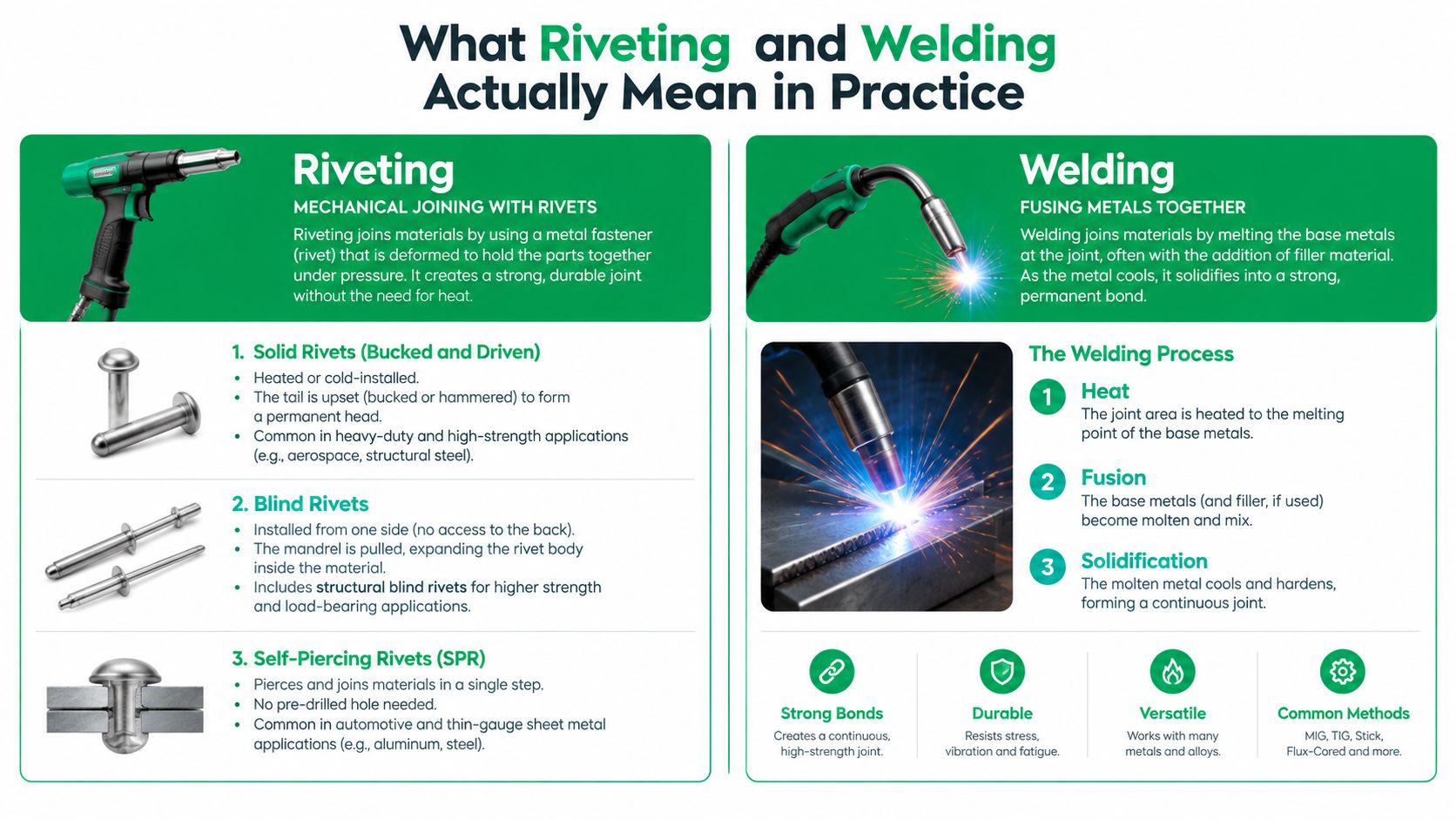
What Riveting and Welding Actually Mean in Practice- Riveting options that matter in sheet metal
- Welding options that matter in thin-gauge fabrication
- Shared assumptions for the rest of this article
Side by Side on Strength, Sealing, and Manufacturability- Where welds earn their keep
- Where rivets are the adult decision
- Inspection and shop-floor reality
- Don't confuse “strong” with “easy to manufacture”
Why Fatigue Performance Breaks the Old Assumptions- The modern data is not one-sided
Choosing the Right Method for Prototyping and Low-Volume Runs- Start with material and stack-up
Cost Drivers and Inspection Burden at Small Batches- Where the real cost sits
A Practitioner's Decision Checklist for Your Next Build- Six checks before release
The Joining Decision Every Sheet Metal Engineer Faces
A typical product team hits this choice in three places at once. First, a cold-rolled steel bracket that supports a motor, sensor mast, or hinge. Second, a formed aluminum enclosure where heat distortion can ruin fit-up across multiple bends. Third, a 2 mm stainless service panel that looks simple until serviceability and cosmetics collide.

The wrong call at prototype stage creates expensive follow-on work. I've seen teams weld early builds because it felt fast, then discover the structural reviewer wanted a joint that was easier to inspect consistently across repeated assemblies. Suddenly the prototype can't support the validation path, and the team has to redraw tabs, holes, edge distances, access windows, and finishing steps.
What actually decides it on the floor
Abstract strength charts don't answer the practical questions:
- Can the operator reach both sides? Solid rivets and many resistance weld setups care. Blind rivets don't.
- Will the assembly ever be opened in service? If yes, a permanent weld across the wrong seam is a design mistake.
- Is the joint visible? Welded seams can look cleaner, but heat tint, spatter, grinding marks, and local distortion can make them uglier than a neat rivet pattern.
- Will the build stay under a few hundred parts? If yes, setup burden matters more than textbook cycle time.
The decision changes with the part, not the ideology
A welded frame with riveted skins is often smarter than trying to pick one religion for the entire assembly. Use welding where you need monolithic structure or sealing. Use rivets where you need access, modularity, or low-risk iteration.
Practical rule: If the joint location controls future service access, start by asking how it comes apart, not how it goes together.
That mindset saves more programs than arguing about ultimate strength in a vacuum.
What Riveting and Welding Actually Mean in Practice
Engineers throw around “rivet” and “weld” as if each is one process. It isn't. The decision only gets clear when you name the specific joining method and match it to geometry, access, and material.
Riveting options that matter in sheet metal
Solid rivets are the old-school structural answer. You insert the rivet through a prepared hole and deform the tail with a bucking bar or squeezer. They need access from both sides and decent process control, but they're reliable when the joint is designed properly.
Blind rivets install from one side. That makes them the default answer for closed sections, boxed enclosures, and retrofit work where the backside disappears after bending or assembly. Structural blind rivets push this category further when you need higher clamp and better retained mandrel behavior than basic pop rivets.
Self-piercing rivets, usually called SPR, are different. They don't require pre-drilling in the same way conventional rivets do. The rivet pierces and flares into the lower sheet under controlled tooling. That makes SPR attractive for thin sheet stacks, coated materials, and mixed-material assemblies where heat is a problem.
Welding options that matter in thin-gauge fabrication
Resistance spot welding is common on overlapped sheet steel. It's fast, repeatable, and automatable if the geometry lets electrodes reach the joint. It's less forgiving when flange access is poor.
MIG or MAG welding fits structural members and thicker sheet assemblies where speed matters more than show-quality cosmetics. On thin sheet, it can work, but distortion control and edge prep become touchy quickly.
TIG welding is what teams reach for on stainless panels and aluminum parts when appearance and heat control matter. It's slower and more operator-sensitive, but it gives better control on visible seams and tighter assemblies.
Friction stir welding is worth noting for aluminum enclosures and longer seams. It avoids the classic fusion-weld profile, but it's still a specialized process with tooling and path constraints.
If your team needs a quick process overview for common sheet metal weld choices, FIRMFG's page on sheet metal welding methods is a useful reference.
Shared assumptions for the rest of this article
Most of the design advice here assumes conventional cold-rolled steel and common aluminum sheet such as 5052 or 6061, unless noted otherwise. Stainless behaves differently in finishing and distortion. Dissimilar stacks create their own corrosion and process headaches. Don't copy a steel answer into aluminum and expect the same result.
Side by Side on Strength, Sealing, and Manufacturability
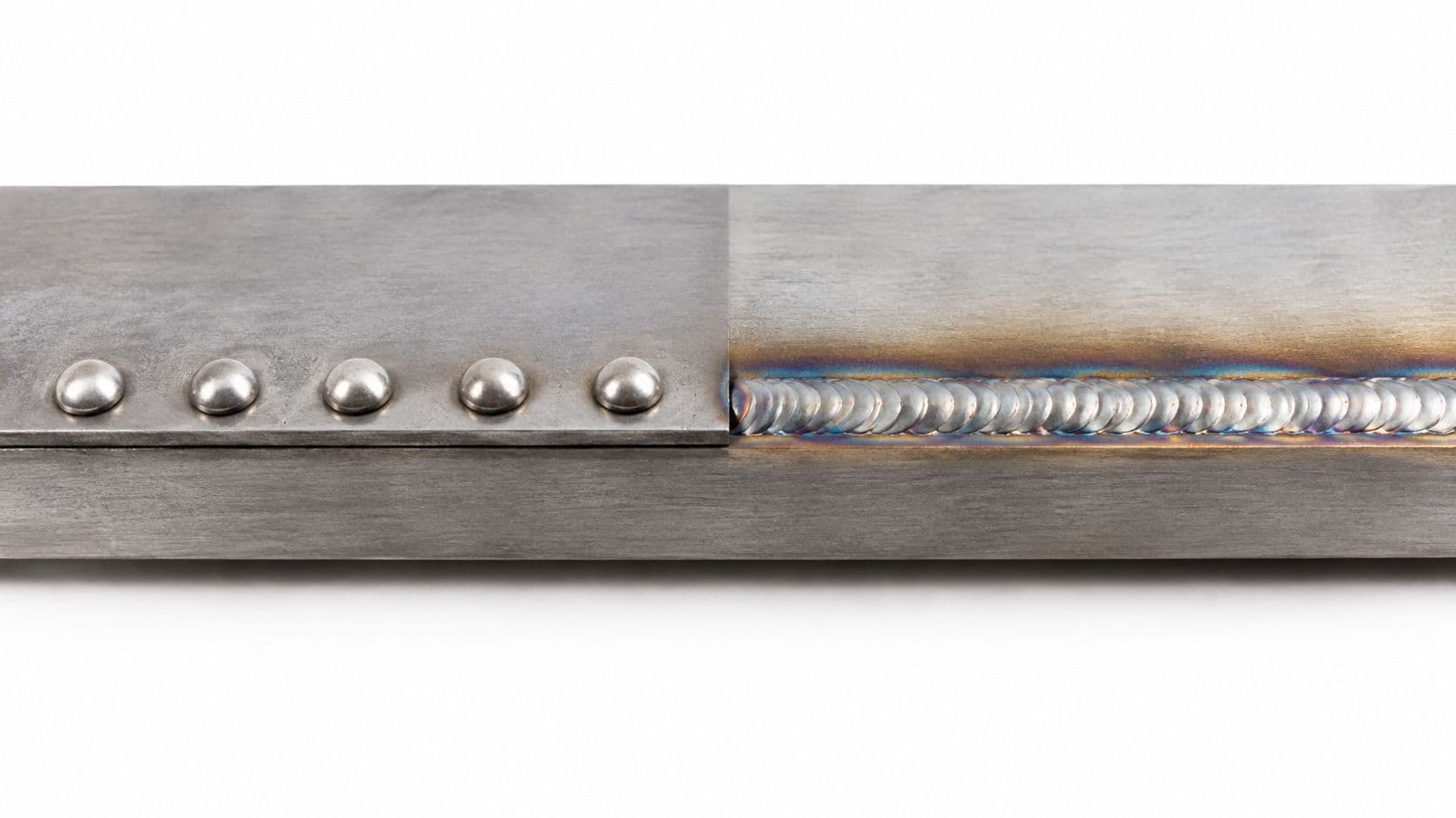
Here's the short version. Welding wins when you need a continuous sealed seam or a monolithic frame. Riveting wins when access, serviceability, low-volume setup, or heat-sensitive geometry drives the build.
| Criterion | Riveted Joint | Welded Joint |
|---|---|---|
| Static load transfer | Good in shear when spacing, edge distance, and grip are designed correctly | Strong continuous bond when weld size and penetration are correct |
| Fatigue behavior | Can be very good or poor depending on hole pattern, clamp, and bearing behavior | Can be very good or poor depending on toe geometry, residual stress, and heat-affected zone |
| Sealing | Usually needs sealant or gasket strategy | Best choice for airtight or watertight seams |
| Disassembly | Can be drilled out and replaced | Usually destructive to remove |
| Heat distortion | No heat distortion from joining itself | Distortion risk is real, especially on thin sheet and cosmetic panels |
| Visible finish | Fastener heads remain visible | Seam can be blended smooth, but grinding and heat marks add work |
| Mixed materials | Practical option for dissimilar stacks | Often limited or impractical |
| Inspection burden | Simple visual checks and dimensional verification | May need more process control and additional inspection methods |
| Prototype friendliness | Strong choice for quick iteration | Setup can be heavy for small batch work |
| Closed-section access | Blind rivets work well from one side | Weld access may be awkward or impossible inside tight geometry |
Where welds earn their keep
If you need a seam to contain water, dust, pressure, or washdown exposure, welding is the default answer. A continuous weld bead solves a sealing problem that a row of fasteners can only approximate with sealants, gaskets, or secondary operations.
Welding also makes sense when the joint must act like one continuous member. Think machine bases, welded frames, tank corners, or support structures where you don't want discrete fastener spacing dictating load transfer.
Where rivets are the adult decision
Rivets are better when the assembly has a real rework path. If a field technician needs to remove a side panel, replace a fan tray, swap an internal module, or correct damage without cutting tools, welding is the wrong choice at that seam.
They also shine when the part geometry is thin, bent, and easy to warp. A long flange on an aluminum enclosure can move enough under welding heat to chase your tolerance stack all over the assembly. Rivets don't create that problem.
If the panel has to come off later, don't weld it on because it looks cleaner in CAD.
Inspection and shop-floor reality
On a low-volume floor, engineers argue about what's easier to trust. A riveted joint is usually straightforward to inspect visually. You check hole location, edge distance, head formation, clamp-up, and obvious sheet damage. A caliper and trained eyes go a long way.
A weld needs more discipline. You're watching fit-up, tack sequence, bead placement, undercut, burn-through risk, local warp, and post-finish appearance. Even when the weld is structurally fine, distortion can still make the assembly functionally bad.
Don't confuse “strong” with “easy to manufacture”
A 2 mm lap joint may look simple in the model. In production, the easier joint is often the one the operator can fixture repeatably, inspect quickly, and rework without scrapping the whole assembly.
That's where many rivets vs welding decisions are won. Not in the strength textbook. In the build review.
Why Fatigue Performance Breaks the Old Assumptions
The old shortcut says welding is stronger, so welding must be better. That shortcut fails the minute the joint sees repeated loading.
Early aircraft-structures work didn't focus only on static strength. It compared riveted and welded joints on fatigue, because crack growth at holes and weld toes often controlled service life. One independent technical review notes that pinned and riveted joints can have only 50% to 30% of the fatigue strength of welds, while another aircraft-joint study found riveted joints with little shear load were about 30% weaker in fatigue than plain sheets, largely from stress concentration around rivets, as summarized in this DTIC technical review of aircraft structural joining history. That historical record matters, but don't oversimplify it. The same body of work also shows multi-row and stiffened riveted joints performed better than simple lap joints.
The modern data is not one-sided
Recent comparative data makes the same point more clearly. In one stainless-steel comparison, at 2 million cycles the riveted joint reached a nominal stress of 37 MPa, while the welded joint reached 20 MPa under nominal-stress evaluation. Under Maddox stress, the rivet case was about 248 MPa versus 169 MPa for welds, and under bearing stress 190 MPa versus 153 MPa. The same source also cites a 2025 numerical fatigue study of dissimilar lap joints where dimple spot welding specimens had fatigue lives about 10 times longer than self-piercing riveting specimens made from the same materials, in this published fatigue comparison for riveted, spot-welded, and related joints.
So no, the answer isn't “welding always wins” or “rivets always win.” The answer is that joint geometry, material pair, and stress definition decide it.
| Joint Type | Cycles to Crack Initiation | Failure Mode | Residual Stress State |
|---|---|---|---|
| Simple riveted lap joint | Varies strongly with hole quality, clamp, and load path | Crack initiation around hole or bearing damage | Often influenced by local clamp and contact pressure |
| Multi-row or stiffened riveted joint | Better than simple lap layouts in many practical designs | More distributed load sharing | Depends on fastener pattern and assembly method |
| Thin-sheet fusion weld | Often limited by weld toe effects and heat-affected zone behavior | Toe cracking or local fatigue crack growth | Commonly includes tensile residual stress near the weld |
| Dimple spot welded lap joint | Can outperform self-piercing rivets in some dissimilar lap-joint studies | Localized cyclic damage around spot region | Process-dependent |
| Self-piercing riveted lap joint | Can outperform welds in some layouts and lose badly in others | Bearing, sheet tearing, or hole-edge damage | Clamp-driven and geometry-dependent |
What engineers should do with that information
If the joint will see vibration, repeated opening loads, motor excitation, road inputs, or operator abuse, don't approve it on static load logic alone. You need to think about where the crack starts. In welds, that's often the toe or heat-affected region. In riveted joints, it's often around the hole, bearing surface, or a poor load path.
A second useful correction comes from bridge and stainless-steel connection research. Riveted joints can match or exceed welded details in fatigue life when clamping force and bearing ratios are favorable, and riveted built-up members may have higher fatigue strength than welded ones under practical live-load ranges, as discussed in this Lehigh research paper on fatigue behavior of riveted and welded connections.
Design warning: If your fatigue life depends on a simple overlapping sheet seam, the local detail matters more than your process preference.
Choosing the Right Method for Prototyping and Low-Volume Runs
At prototype stage, the smartest joining choice is usually the one that preserves options. You're still learning what needs to move, what needs to come apart, and which tolerances are fake precision on the first release.
Start with material and stack-up
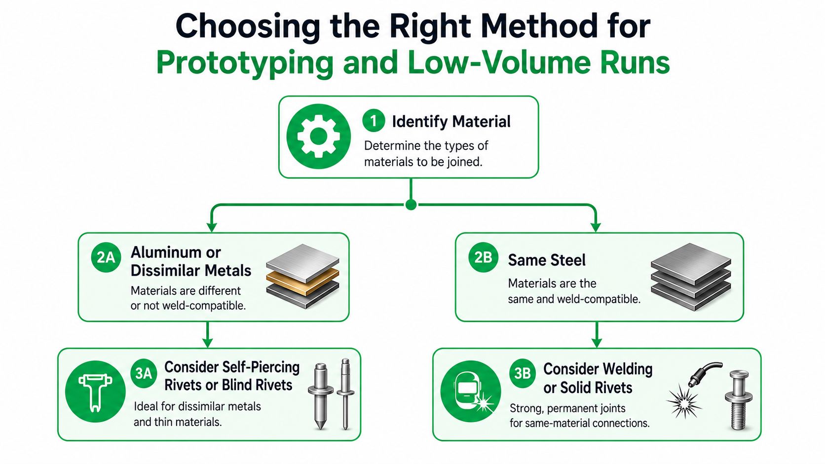
If the assembly is aluminum, especially a bent enclosure or cosmetic shell, I'd push hard toward blind rivets or self-piercing rivets unless the seam needs to be continuous and sealed. No heat means no heat-affected zone, no filler cleanup, and far less risk of a panel that suddenly rocks on the bench after welding.
If you're joining dissimilar materials, riveting usually wins by default. Welding those stacks either isn't practical or drags in process complexity that doesn't belong in a prototype budget.
For thin steel sheet, spot welding or projection-style approaches can make sense if the flange geometry is cooperative and the build is repeatable. For heavier structural steel members, MIG or TIG starts to make more sense because the structure can absorb heat and justify the permanent joint.
Then look at quantity honestly
For very small prototype counts, riveting usually beats welding because setup is lighter and rework is cleaner. You can change a hole pattern, adjust a flange, or replace a panel without cutting apart a whole subassembly.
The gray zone is pilot and low-volume work. That's where the process burden matters more than ideology. If the team needs iteration speed and drawing churn is still active, riveting remains the safer bet. If the design is frozen, fixturing is stable, and the seam needs sealing or a cleaner exterior, welding becomes more defensible.
If your team is still validating manufacturability, a partner that handles iterative prototype sheet metal fabrication can help sort out whether the drawing really supports one-sided riveting, spot welding access, or post-weld finishing without ugly surprises.
Four common scenarios and the right answer
- Prototype aluminum enclosure: Use blind rivets or SPR. Thin formed aluminum punishes unnecessary heat.
- Low-volume steel chassis: Use welding for the main frame, then rivet non-structural covers and service panels. Hybrid assemblies are often the grown-up answer.
- Repair-friendly stainless service panel: Use rivets unless the seam must be sealed permanently. Serviceability should beat aesthetic purity.
- Visible exterior skin: Use welding only if you can control distortion and finish work. Otherwise a deliberate rivet pattern can look more professional than a wavy ground seam.
The practical threshold
The build count isn't the only variable, but it does force honesty. If you don't have stable fixtures, consistent weld procedure control, and a real inspection plan, welding too early creates debt. Riveting gives you a wider path to learn before you commit.
Cost Drivers and Inspection Burden at Small Batches
At small batch sizes, the part cost isn't driven by theory. It's driven by setup, handling, and how many chances the process gives you to be wrong.
Where the real cost sits
Riveting usually starts cheap because the tools are simple, fixtures are lighter, and the operator can work around minor variation. You still pay for drilling or piercing, hole alignment, hardware management, and sometimes sealant. But the startup friction is low.
Welding is different. The direct arc time is only part of the bill. You also pay for fixturing, tack strategy, distortion control, operator skill, cleanup, gas management, and more disciplined first-article review. On a tiny batch, those overheads dominate.
| Joining Method | Per-Joint Cost (USD) | Setup Time | Inspection Method | Rework Difficulty |
|---|---|---|---|---|
| Blind or solid riveting | Not fixed. Usually lower setup burden at small batch | Short to moderate | Visual check, dimensional check, head formation review | Usually moderate and localized |
| Self-piercing riveting | Not fixed. Tooling-dependent | Moderate | Visual and section validation during process setup | Moderate |
| Spot welding | Not fixed. Access and fixture dependent | Moderate to high | Visual process checks, nugget validation methods where required | Moderate to difficult |
| MIG welding | Not fixed. Labor-heavy in low volume | High | Visual weld inspection, possible penetrant or additional checks for critical joints | Difficult |
| TIG welding | Not fixed. Typically the slowest labor route on thin visible parts | High | Visual appearance plus quality checks tied to the application | Difficult |
Inspection burden changes the economics
A rivet line is easier to audit. You can verify placement, clamp-up, and obvious defects without a lot of secondary effort. If one joint is bad, you can often drill it out and replace it.
A weld is more expensive when quality requirements rise. Critical joints may need penetrant testing, sectioning during setup validation, or tighter process documentation. Even when formal NDT isn't required, someone still has to judge bead quality, distortion, and fit after joining.
Rework is where bad decisions get exposed
If the drawing will change, riveting keeps rework local. If the weldment distorts or a seam lands in the wrong place, rework can spread across the assembly fast. You're grinding, blending, refinishing, and hoping the heat from the fix doesn't create a second problem.
For teams trying to estimate low-volume economics realistically, this matters more than piece-part optimism. The expensive method isn't always the one with the higher direct labor minute. It's the one that punishes every revision. A cost breakdown like this should be part of any early sheet metal fabrication cost planning.
A Practitioner's Decision Checklist for Your Next Build
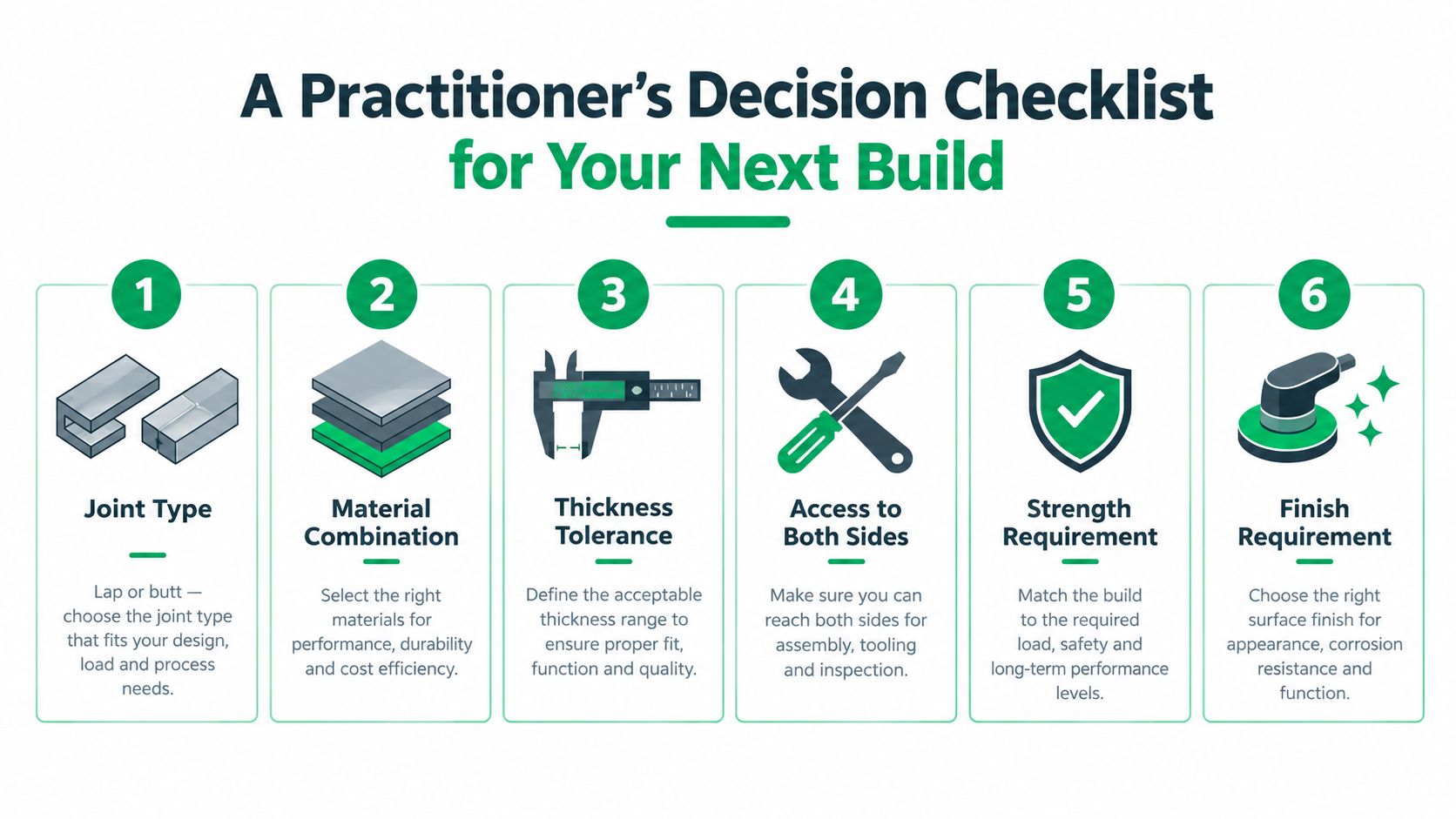
Most bad choices in rivets vs welding happen because teams skip one basic question too early. Run this checklist before you lock the drawing.
Six checks before release
- Identify the joint type. A lap joint gives you many fastener options. A butt joint pushes you harder toward welding unless you redesign with backing features or added hardware.
- Confirm material combination and thickness stack. Mixed metals and thin aluminum usually steer toward riveting. Similar, thicker structural metals are more welding-friendly.
- Ask whether the assembly must come apart. If service access matters, don't pretend a permanent seam is elegant. It's a future maintenance problem.
- Separate static load from fatigue load. If the joint sees repeated cycling, detail design matters more than broad process assumptions.
- Estimate real build quantity. Prototype logic and stable production logic aren't the same. Don't choose a process for a future volume you haven't earned yet.
- Check inspection access and in-house capability. If you can't inspect or repeat the weld confidently, a theoretically better welded joint isn't better.
My recommendation matrix
- Choose rivets for mixed-material stacks, serviceable panels, enclosure prototypes, and builds where geometry or cosmetics can be wrecked by heat.
- Choose welding for sealed seams, structural frames, and assemblies that benefit from behaving like one continuous metal body.
- Choose both when the frame needs permanence but the skins, access covers, or internal mounts need flexibility.
The best joining method is the one your drawing, your operator, and your inspection plan can all support without drama.
When the batch size scales and the product stabilizes, revisit the decision. A prototype-friendly riveted seam may deserve to become a welded production seam later. The reverse is also true if field service starts driving warranty pain.
FIRMFG supports this kind of decision with sheet metal fabrication, riveting and hardware insertion, plus TIG, MIG, spot, and projection welding for prototype and low-volume metal assemblies. If you're deciding between a serviceable riveted build and a welded production path, FIRMFG can review the geometry, process fit, and manufacturability before you lock the drawing.