Spot Facing vs Counterboring Explained
You're reviewing a bracket that looks straightforward in CAD. The mounting hole is in the right position, the socket-head screw fits the thread, and the model passes interference checks. Then the part arrives from a rough casting, the screw head rocks on an uneven pad, and tightening the joint bends the bracket instead of creating a stable clamp.
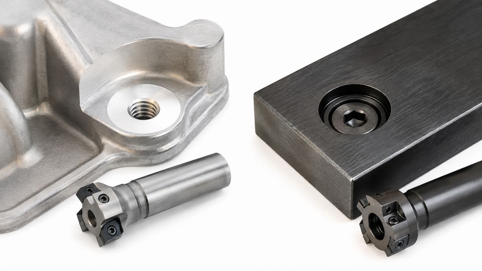
That failure often starts with treating spot facing vs counterboring as a depth choice. It isn't. The two operations solve different assembly problems. A spotface creates a local, flat bearing land. A counterbore creates a cylindrical recess that provides clearance for a fastener head.
| Feature | Primary purpose | Typical starting surface | Fastener result | Main design concern |
|---|---|---|---|---|
| Spotface | Creates a clean, flat seating area | Cast, forged, curved, or irregular stock | Head, nut, or washer remains supported at the surface | Reliable bearing and load distribution |
| Counterbore | Recesses the fastener head | Usually a sufficiently accessible machined or prepared face | Head sits flush or below the surface | Diameter, depth, and head clearance |
| Countersink | Creates a conical recess | A face designed for an angled head | Flat-head screw sits flush | Cone angle and fastener match |
Table of Contents
Core Geometry and Functional Differences- The surface is the deciding feature
Drawing Callouts and Standard Dimensions- A practical callout sequence
Tooling and Machining Approaches on the Shop Floor- Uneven stock creates the real difficulty
Tolerances, Surface Finish, and DFM Guidelines- Specify only what the joint needs
Real-World Use Cases and Decision Matrix- When a shallow counterbore is better
Final Recommendations for Precision Assemblies
The Hidden Cost of Confusing Hole Features
A production team once receives a cast housing with a shallow cylindrical recess around each mounting hole. The CAD model calls it a counterbore, but the recess isn't deep enough to contain the socket-head screw. Worse, the casting surface varies around the hole, so the fastener bears on a narrow high spot rather than a continuous flat land.
During assembly, the operator tightens the screw. The head pulls the bracket toward the casting, the bracket twists, and the gasket compresses unevenly. The joint may hold during a quick bench check, but vibration and repeated thermal cycling expose the problem. The material isn't necessarily too weak. The load enters the part through an unreliable seating surface.
That distinction matters:
- A spotface removes local surface irregularities and produces a flat, perpendicular bearing area for a washer, nut, or fastener head.
- A counterbore removes enough material to form a defined cylindrical pocket around the hole, allowing the fastener head to sit below or flush with the surrounding surface.
The terms are close enough to be confused in design reviews, especially when a shallow counterbore appears visually similar to a spotface. Functionally, though, one prepares a bearing surface and the other creates head clearance.
Why the mistake survives CAD review
CAD software shows nominal geometry. It doesn't automatically tell you whether a rough casting will provide a stable clamp load, whether the washer will fully contact the machined land, or whether a gasket will bridge an unintended step. A model can therefore be dimensionally coherent while still being mechanically wrong.
The problem also travels easily through procurement. A machinist who sees an underspecified feature may interpret it according to the available cutter, the fastener head, or common shop practice. That creates avoidable variation between suppliers and makes first-article inspection harder.
Practical rule: Specify the assembly function first, then select the hole feature that delivers it. Don't use “counterbore” as a casual synonym for any flat-bottomed cut.
The ASM Handbook machining volume from 1989 grouped countersinking, counterboring, and spotfacing as standard hole-preparation operations. These features have long been mature machining practices, but their maturity doesn't make their design intent interchangeable.
Core Geometry and Functional Differences
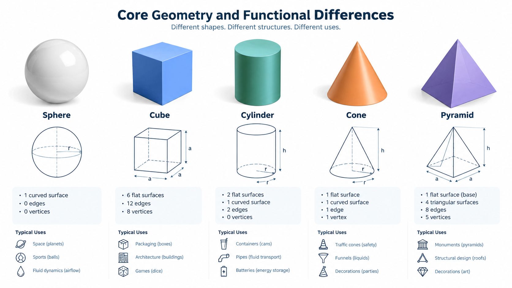
A spotface is a surface-preparation cut. The cutter removes only enough stock to eliminate the local high spots, draft, scale, or curvature that would prevent a fastener or washer from sitting squarely. The resulting floor is shallow relative to a counterbore, and the outside surface of the part remains substantially intact.
A counterbore is a recess-making cut. Its larger cylindrical diameter extends from the hole entrance to a controlled bottom depth. The recess is sized around the actual fastener head, not merely around the hole diameter. If the design requires a flush socket-head screw, the bottom depth must account for the head height and a deliberate amount of clearance.
The surface is the deciding feature
On rough, curved, forged, or cast stock, the load path usually determines the choice. A bolt head or washer needs a continuous bearing area. If the surrounding face is angled, the fastener can tilt, concentrate force at an edge, and lose predictable clamp behavior. A spotface corrects that local condition without removing the volume required to hide the head.
A counterbore becomes the better choice when an exposed head would collide with a moving component, catch on adjacent hardware, or violate the required external profile. It also protects the head inside a pocket, but that protection comes with a deeper cut and greater dependence on accurate depth control.
| Design question | Choose spotface when | Choose counterbore when |
|---|---|---|
| Is the source surface irregular? | Yes, and the head or washer can remain proud | Only if the recess itself is needed |
| Must the head be below the surface? | No | Yes |
| Is the load carried through a washer or broad bearing face? | Usually | Only if the washer and pocket are designed together |
| Is there moving hardware above the joint? | Not usually | Often |
| Does the pocket weaken a thin wall? | Avoids unnecessary removal | Requires a wall and depth review |
A spotface can be shallow and still demand good perpendicularity. A counterbore can be perfectly concentric and still fail if its bottom is too shallow for the fastener head. The first controls how the load enters the part. The second controls where the head ends up.
Drawing Callouts and Standard Dimensions
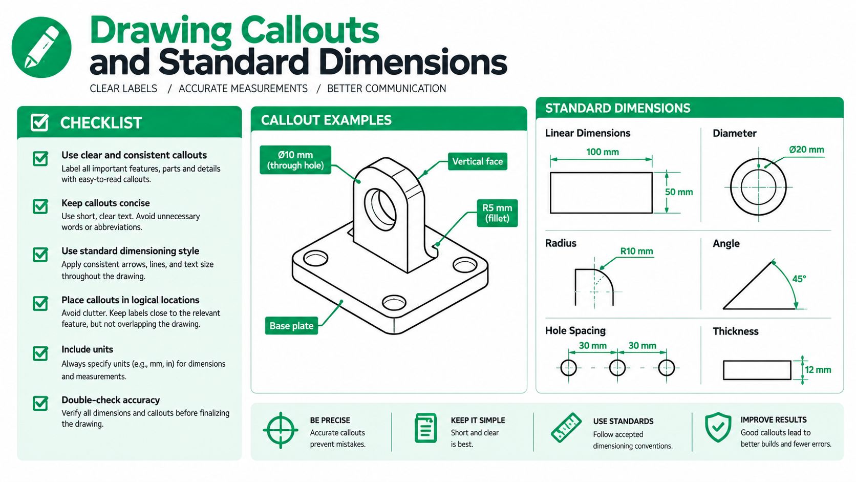
A drawing must distinguish a bearing preparation from a recess intended to hide a fastener head. The common counterbore symbol is ⌴. A spotface usually uses the same symbol with SF added. Include the feature diameter, depth where applicable, and its relationship to the pilot or through-hole. On rough or curved stock, the callout should also make the required seating surface clear. A diameter alone may leave the machinist unsure whether partial contact is acceptable.
For a counterbore, identify the fastener first. Metric socket-head cap screws are selected by standard, not shop preference. ISO 273 and ISO 4762 guidance for metric socket-head fasteners relates the recess geometry to the specified fastener, while DIN 974 addresses spotface practice in European applications.
A practical callout sequence
- Identify the fastener. State the screw or bolt standard, nominal size, and head style in the drawing or bill of materials.
- Define the pilot hole. Specify the clearance, tapped, or through-hole diameter separately when its relationship to the feature affects assembly.
- Define the counterbore diameter. Allow 0.5 mm to 1.5 mm over the head size, based on assembly clearance and the applicable fastener specification.
- Define the depth. For flush mounting, start with the head height plus 0.1 mm to 0.5 mm. Precision assemblies may require depth control as tight as ±0.1 mm.
- State the datum relationship. If the seating floor must be perpendicular to the hole axis or controlled from a functional datum, apply the relevant GD&T requirement instead of leaving it implied.
For a spotface, specify the spotface diameter and identify the hole it serves. The required land should not be inferred from the washer. If the washer must sit fully supported on cast, forged, or curved stock, state the seating condition and size the spotface around the washer's outside diameter. The practical guide to geometric dimensioning and tolerancing can help connect that requirement to datums, orientation, and inspection.
ASME Y14.5 provides the symbolic language, but it does not choose the feature diameter or depth. Those values must reflect the fastener, washer, available wall thickness, and required contact on the actual surface. A shallow spotface can be functionally wrong if it leaves an angled or incomplete bearing land. A counterbore can meet its diameter callout yet still fail assembly if the head bottoms before the joint clamps.
Drawing check: If the print permits either a shallow bearing land or a deep head pocket, it has not communicated the design intent clearly enough.
Tooling and Machining Approaches on the Shop Floor
The tool choice follows the feature's purpose. A counterbore cutter commonly uses a pilot that runs inside the pre-drilled hole. That pilot keeps the larger cutter concentric with the hole and reduces the chance that the recess wanders, chatters, or enters off-center.
The normal sequence is straightforward. The machine establishes the pilot or through-hole, then uses the counterbore tool to cut the larger diameter to its programmed depth. A rigid setup, short tool projection, and controlled chip evacuation matter because the cutter is removing a meaningful volume from the top of the part.
Spotfacing can use a dedicated spotface cutter, a flat-bottomed counterbore-style tool, or a flat end mill. The choice depends on access, diameter flexibility, material condition, and whether the machine can keep the tool axis perpendicular to the intended bearing plane.
Uneven stock creates the real difficulty
A spotface on a flat machined plate is usually routine. A spotface on a casting with hard scale is different. The cutter may enter only on one side, which creates an interrupted cut and a strong tendency toward vibration. If the workholding supports the part on a rough surface, clamping can also distort the casting and change the finished seating plane after release.
The CNC machining process overview is useful context for understanding why setup, workholding, tool access, and sequencing affect more than cycle time. Engineers often see one feature in CAD, while the shop sees an interrupted cut, a long tool, a difficult clamp, and a second inspection requirement.
A five-axis machine can improve the approach on curved stock by orienting the spindle normal to the local seating surface. That may eliminate a custom fixture, but it doesn't eliminate the need to define the desired plane. The machine still needs a clear surface normal, adequate cutter clearance, and a stable reference.
What commonly goes wrong
- A pilot binds. The counterbore pilot is too large for the existing hole, creating galling or forcing the tool off its intended path.
- The cutter chatters. The setup is flexible, the tool is too long, or the first contact with cast scale is too aggressive.
- The floor isn't square. The tool follows the machine axis while the functional bearing plane is angled.
- Burrs remain at the transition. The operation lacks a suitable finishing pass or chip evacuation is poor.
A good CAM programmer can work around some of these conditions, but the design should not depend on rescue programming. The part should present a feature that the selected machine, cutter, and fixture can make repeatably.
Tolerances, Surface Finish, and DFM Guidelines
Set tolerance from the joint's load path and failure mode, not from the feature name. A spotface supporting a standard washer needs a stable bearing land. A counterbore controlling screw-head clearance needs dependable depth and wall-thickness control.
For spotfacing, a practical cleanup operation may remove about 0.3 mm to 1 mm of stock. Typical flatness is around 0.05 mm to 0.1 mm, perpendicularity around 0.1 mm per 25 mm of diameter, and surface finish around Ra 3.2 μm to 6.3 μm. Use these as functional starting points, not automatic drawing requirements. Rough castings, forgings, and curved stock may need more attention to seating condition than to nominal feature depth.
Specify only what the joint needs
For a washer-supported joint, check whether the spotface is wide enough, flat enough, and suitably oriented to the hole axis. If the washer remains fully supported, tighter depth control may add inspection cost without improving clamp load. On irregular or drafted stock, confirm contact around the washer rather than accepting a single depth reading as proof of seating.
Counterbore depth has a more direct effect on assembly. A shallow recess can leave the head proud and interfere with a cover or moving component. An excessive recess can reduce wall thickness, weaken a boss, or let the fastener bottom against an unintended surface. Precision assemblies may require depth control as tight as ±0.1 mm, but clearance, stack-up, sealing, or alignment should justify that requirement.
Surface finish should match contact function. A spotface generally needs a clean, stable bearing surface, not a decorative finish. The surface roughness chart helps relate a finish callout to the actual bearing or sealing requirement. Avoid specifying a finer finish across every recessed feature when the hardware and load path do not benefit from it.
A DFM review that works
- Start with the mating hardware. Check the actual head, washer, nut, gasket, or seal contact area.
- Protect the remaining section. Review the counterbore against wall thickness, ribs, bosses, and nearby cavities.
- Control orientation where it affects clamp load. Add perpendicularity or an equivalent datum relationship when a tilted bearing plane could reduce contact.
- Avoid cosmetic precision. Do not demand fine finish or unusually tight depth for a concealed spotface with no sealing or alignment function.
- Inspect seating, not depth alone. Use a washer, gauge, contact check, or other suitable method when an irregular casting could leave unsupported areas.
A tolerance boundary should match the failure boundary. If protruding hardware causes the failure, control counterbore depth. If washer rocking causes it, control the spotface plane and bearing diameter.
Real-World Use Cases and Decision Matrix
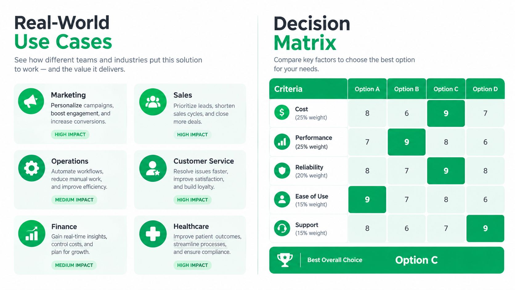
The most useful question isn't “How deep is the cut?” It's “What must remain stable after the fastener is tightened?” That shifts the review toward surface condition, hardware geometry, and the way the joint carries load.
| Assembly situation | Surface condition | Hardware concern | Preferred feature | Reason |
|---|---|---|---|---|
| Cast fluid reservoir with a bolt and washer | Rough or drafted | Washer must sit evenly | Spotface | Creates a local bearing land without hiding the head |
| Robotics chassis bracket near a moving arm | Machined or prepared | Head clearance is limited | Counterbore | Removes interference and places the head below the surface |
| Curved extrusion with a gasketed joint | Curved | Compression must remain uniform | Spotface or shallow counterbore, based on the gasket and head | The flat seating plane matters more than nominal depth |
| Medical enclosure with an internal socket screw | Finished exterior | External surface must remain unobstructed | Counterbore | Protects the head and preserves the envelope |
| Flange using a broad washer on forged stock | Irregular | Full washer contact is required | Spotface | Prevents point loading and fastener tilt |
| Thin housing wall with a socket-head screw | Limited remaining section | Recess could weaken the wall | Spotface, if head clearance allows | Avoids unnecessary material removal |
When a shallow counterbore is better
A shallow counterbore can be functionally superior to a conventional spotface when the assembly needs more than a flat land but less than full head burial. For example, a gasket may need a controlled compression shoulder, or an O-ring carrier may need a defined cylindrical boundary around the fastener. In that situation, calling the feature a spotface can hide the fact that the recess depth and diameter participate in the seal or stack-up.
The reverse is also true. A designer may model a deep counterbore because the CAM library offers one, even though a washer needs only a perpendicular seat. That choice removes material, adds depth inspection, and can reduce structural margin without improving the joint.
The assembly test that settles the argument
Load the actual fastener, washer, gasket, or seal into the prototype. Look for rocking, witness marks, uneven compression, head interference, and contact outside the intended land. A feature that looks correct in a shaded CAD view can fail this physical check because the casting surface, coating, burr condition, or hardware variation changes the contact pattern.
Select a spotface when the part needs a reliable bearing plane. Select a counterbore when it needs a defined head pocket. If it needs both, model and call out both functions rather than hoping one vague term covers them.
Final Recommendations for Precision Assemblies
Review hole preparation as part of the joint design, not as a finishing detail added after the main geometry is complete. The right feature depends on the surface that exists before machining, the hardware that will contact it, and the clearance envelope around the assembled part.
Use this checklist before releasing the CAD model:
- Confirm the failure mode. Is the risk poor seating, head interference, gasket compression, or insufficient wall thickness?
- Inspect the starting face. Treat cast, forged, curved, and drafted surfaces differently from fully machined faces.
- Match the feature to the hardware. A washer-bearing joint and a recessed socket-head screw need different geometry.
- Define the functional plane. Add orientation control when a tilted fastener would change clamp load.
- Size the recess from the fastener. Don't leave counterbore diameter or depth to shop judgment.
- Avoid excess removal. A spotface shouldn't become a deep pocket just because the cutter is available.
- Review the inspection method. Decide whether the supplier must verify diameter, depth, flatness, perpendicularity, or actual seating.
- Ask for DFM feedback early. A manufacturing partner should flag long tools, interrupted cuts, poor support, and inaccessible surfaces before programming.
Standards such as ISO 273 and ISO 4762 help anchor metric fastener geometry, but standards don't replace assembly reasoning. Your drawing should make the intended load path and clearance condition obvious to the designer, machinist, inspector, and assembler.
A reliable rule of thumb is simple. Spotface for stable bearing on imperfect stock. Counterbore for controlled head clearance. When the joint needs both, specify both and verify the assembled condition.
FIRMFG provides CNC rapid prototyping and precision machining for metal and plastic parts, including 3-, 4-, and 5-axis milling, turning, inspection, and DFM feedback for features such as spotfaces and counterbores. Share your CAD model and drawing with FIRMFG to get manufacturing guidance for the correct seating surface, fastener clearance, tooling approach, and low-volume production path.