What Is Sheet Metal Fabrication and How Does It Work
Sheet metal fabrication is the set of manufacturing processes that cut, bend, and join flat metal sheets into finished parts. The global sheet metal fabrication market was estimated at about USD 220 billion in 2023 and is projected to reach roughly USD 300 billion by 2030, which shows why process selection matters far beyond a one-off bracket. Industry market estimates place the work at the center of construction, transportation, appliances, and industrial equipment.
You may be looking at a flat DXF file on one screen and a three-dimensional bracket on the other, wondering why the quotation changed after you added two holes and a return flange. The answer usually begins before any metal reaches the shop floor. Material grade, thickness, bend radius, hole placement, finish, and production volume determine whether the part should be laser cut and bent, punched, stamped, welded, or made by another process entirely.
A useful way to understand the subject is to follow a part through the shop. Start with flat stock, cut the profile, form the geometry, add hardware or weldments, apply the finish, and inspect the features that matter to assembly. The right process path can produce a functional prototype quickly. The wrong one can create distorted holes, cracked bends, unnecessary tooling, or a design that needs to be quoted again by several suppliers.
Table of Contents
How Sheet Metal Fabrication Evolved Into a Modern Industry
The Four Core Processes Every Engineer Should Know- Cutting defines the blank
Common Metals, Thicknesses, and Finishes
Design for Manufacturing Basics That Save Time and Money- Start with the bend
How Sheet Metal Compares to Machining and Injection Molding- Where the processes change places
Where Sheet Metal Parts Show Up in Real Products- The same process serves different priorities
How FIRMFG Supports Rapid Prototyping and Low-Volume Production- A capability view for product developers
What Sheet Metal Fabrication Actually Means
An engineer is staring at a flat DXF on a calibration laptop. The drawing shows a rectangular blank with slots, mounting holes, and bend lines, but the finished product needs to hold a sensor at a precise angle. That transformation, from a flat pattern to a useful three-dimensional component, is the practical meaning of sheet metal fabrication.
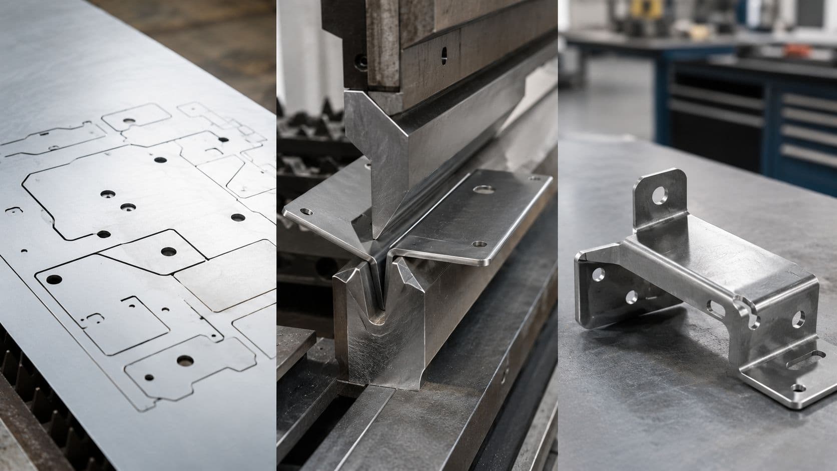
The starting material may arrive as a coil, a flat sheet, or a plate. A fabricator removes material through laser cutting, punching, plasma cutting, or waterjet cutting, then forms the remaining blank with a press brake, roller, or stamping die. Separate pieces can be joined with welding, rivets, screws, clinch hardware, or other fastening methods.
The four operations behind most parts
Most fabricated brackets, enclosures, chassis, guards, and panels rely on four core operations:
- Cutting creates the flat outline, holes, slots, vents, and clearance features.
- Bending turns the blank into flanges, channels, trays, and angular brackets.
- Stamping forms repeated features or complex shapes with dedicated dies.
- Welding joins separate blanks or formed components into an assembly.
A small electrical enclosure might be laser cut from stainless steel, bent on a CNC press brake, fitted with threaded inserts, and powder coated. A high-volume automotive reinforcement may instead use stamping because a die can form repeated geometry efficiently. The part's shape, quantity, material, and tolerance requirements decide the route.
Practical rule: Treat the first sketch as a manufacturing decision, not only a geometry exercise.
Bend allowance and springback affect the flat pattern. Material hardness affects whether a tight corner will crack. A hole positioned too close to a bend may stretch or deform. These issues are easier to solve in CAD than after a prototype arrives, so a DFM review at the sketch stage protects both lead time and dimensional performance.
How Sheet Metal Fabrication Evolved Into a Modern Industry
A hand-shaped metal bracket and a digitally programmed enclosure may look unrelated, yet they follow the same basic logic: start with thin stock, remove only what is needed, then form or join it into a useful structure. Early metalworkers relied on hammering, rolling, pressing, and joining. As rolling mills and presses improved, those operations became more repeatable. A historical timeline places Leonardo da Vinci's rolling-mill sketch in 1485, records rolling mills in use by 1500, and identifies industrial sheet production by 1615. The historical development of sheet metal fabrication traces how improvements in forming and steelmaking established the methods modern shops still refine.
The Industrial Revolution changed the economics of making repeated parts. Joseph Bramah's hydraulic press appeared in 1770, and the Bessemer converter, introduced in 1857, helped produce steel faster and at lower cost. Around 1960, the Basic Oxygen Furnace replaced the Bessemer process, supporting larger and more consistent steel supply chains. For a product developer, the practical result was predictable sheet stock and presses capable of applying controlled force, both of which improve repeatability from one bracket to the next.
Mechanized punch presses and press brakes helped sheet metal become its own discipline beside machining. Machining usually begins with a block, bar, or billet and removes material from several faces. Fabrication begins near the required thickness, then uses cutting and forming to preserve material while flanges and bends create stiffness.

Digital manufacturing shortened the path from drawing to part. A DXF can guide a laser toolpath, while CAD and CAM software can calculate a flat pattern and organize a press-brake sequence. Automated quoting and connected equipment let a modern prototype shop combine laser cutting, bending, stamping, and finishing in one DFM-aware workflow. Engineers can test a bracket without re-quoting five suppliers, and can choose tooling only when volume justifies it.
The Four Core Processes Every Engineer Should Know
A fabricated part usually becomes easier to specify once you understand what each operation forces you to decide. Cutting determines the flat profile. Bending determines how that profile becomes rigid. Stamping determines whether tooling is justified. Welding determines how multiple pieces become one assembly.

Cutting defines the blank
Laser cutting is often the flexible choice for prototypes because a programmed beam can create changing profiles without dedicated hard tooling. It produces flat outlines, slots, and holes, and works well when a design may change between builds. Plasma handles heavier material, waterjet avoids much of the heat input associated with thermal cutting, and punching can be efficient when a part contains many repeated holes or standard forms.
Each method creates a different trade-off. Laser cutting offers detailed geometry and a narrow kerf, but its heat can leave a heat-affected zone. Waterjet cutting limits thermal effects but adds abrasive cutting equipment and cleanup. Punching can be fast for repeated features, but the available tool shapes and spacing influence the design.
Bending creates stiffness
A press brake pushes a flat blank between a punch and die to create an angle. That single operation can turn a flexible sheet into a rigid L-bracket, U-channel, tray, or enclosure. A designer must account for the inside bend radius, bend allowance, bend sequence, and K-factor, which describes how the neutral axis shifts through the thickness during forming.
A bend also introduces springback. The operator or the CNC program compensates by driving the material slightly past the desired angle. If your part has a mounting hole near the bend, the hole location must leave enough material for the sheet to stretch without distortion. For process-specific guidance, review CNC sheet metal bending before finalizing the flat pattern.
Stamping trades tooling for speed
Stamping uses a punch and die to form features, draw shapes, pierce holes, or create ribs and embosses. Unlike press-brake work, where bends are commonly performed in a controlled sequence, a stamping die can combine several operations in a repeatable cycle. That makes stamping attractive when the same geometry will be produced repeatedly at meaningful volume.
The trade-off is upfront tooling. A changing prototype design may not justify a dedicated die, while a stable production design can benefit from the consistency and speed of a matched tool. Progressive dies can feed strip stock through several stations, but the die layout must be engineered before production begins.
Welding and fastening close the loop
Laser cutting and bending can create a complete part from one blank, but some assemblies need separate panels, reinforcements, studs, or brackets. MIG welding suits many structural steel assemblies, while TIG welding offers finer control for stainless steel and visible joints. Spot welding works well for overlapping sheet components, and seam welding can create a continuous joint.
Mechanical fastening remains useful when serviceability matters. Rivets, screws, clinch nuts, and PEM-style hardware avoid some heat distortion and can let a technician replace a panel. The choice depends on load, appearance, corrosion exposure, access for tools, and whether the assembly must be disassembled later.
Common Metals, Thicknesses, and Finishes
Material selection starts with the environment and the load, then moves to forming behavior and appearance. A cheap cold-rolled steel bracket may be ideal inside a dry machine, but an outdoor assembly may need galvanized steel, stainless steel, or a protective coating. Aluminum can reduce weight, while stainless grades support corrosion resistance and cleanability.
Thickness is commonly specified in millimeters or gauge. Thin sheet suits covers, instrument panels, and light brackets. Thicker sheet provides greater stiffness and load capacity, but it requires larger bend radii, more forming force, and careful attention to tool access. The same geometry may be easy to bend in 5052 aluminum and difficult to form in a harder aluminum temper.
| Material | Typical Thickness (mm) | Common Finishes | Best-Fit Applications |
|---|---|---|---|
| Cold-rolled steel | Thin to medium sheet | Mill finish, powder coat, zinc plating | Indoor brackets, chassis, machine panels |
| Stainless steel 304 | Thin to medium sheet | Mill finish, bead blasting, passivation | Enclosures, food equipment, medical housings |
| Stainless steel 316 | Thin to medium sheet | Mill finish, bead blasting, passivation | Corrosive or chemically demanding environments |
| Aluminum 5052 | Thin to medium sheet | Mill finish, powder coat, anodizing | Formed brackets, covers, lightweight enclosures |
| Aluminum 6061 | Thin to medium sheet or plate | Mill finish, anodizing, bead blasting | Machined or formed structural components |
| Galvanized steel | Thin to medium sheet | Zinc-coated surface, powder coat where compatible | Outdoor panels, HVAC components, utility housings |
| Hot-rolled steel | Medium to heavy sheet | Mill finish, paint, powder coat | Structural brackets and industrial frames |
304 stainless steel is a common general-purpose choice when corrosion resistance and a clean surface matter. 316 stainless steel is selected when the environment is more aggressive, but it can increase material and fabrication cost. The right choice isn't automatically the most corrosion-resistant grade. Specify the performance the part needs, then confirm the grade's bend and weld behavior with the fabricator. FIRMFG's overview of stainless steel fabrication is useful when surface condition, welding, and corrosion exposure all affect the decision.
Finishing adds another layer of engineering. Powder coating provides a durable colored surface for many indoor and outdoor enclosures, but it adds masking and curing requirements. Anodizing protects and colors aluminum while preserving a metallic appearance. Zinc plating helps protect steel, while bead blasting changes texture and can reduce visible tool marks.
Material choice is a system decision: strength, formability, corrosion resistance, finish compatibility, inspection requirements, and delivery timing all belong on the same conversation.
Design for Manufacturing Basics That Save Time and Money
DFM isn't a list of arbitrary restrictions. It's a way to keep the geometry compatible with the tools that will cut and form it. A design that follows practical guardrails can move through quoting with fewer questions and reach inspection with fewer surprises.

Start with the bend
For many common sheet-metal designs, set the inside bend radius at or above the material thickness unless the fabricator approves another condition. A radius that is too tight can crack a hard alloy, mark the surface, or require specialized tooling. A consistent radius across the part also simplifies setup.
Holes and slots need clearance from bends. As the material stretches and compresses, a feature placed too close can elongate, close up, or move out of position. Add bend reliefs and corner notches where two formed edges meet, because those cuts give the material room to deform instead of tearing or bulging.
Match tolerances to the process
A drawing should distinguish between cut features, formed dimensions, and critical assembly interfaces. The plan notes identify typical tiers of ±0.1 mm for laser-cut features and ±0.2 mm for bent dimensions, but those values should be confirmed against the chosen material, machine, geometry, and inspection method. Sheet metal fabrication market coverage reinforces the broader point that fabrication supports production chains where lead time and process integration matter, not only isolated handwork.
Use tight tolerances only where function requires them. A sensor-mounting hole may need closer control than the outer edge of a cosmetic cover. Formed features generally need a more practical tolerance because material variation, springback, and tool engagement affect the result.
Choose the cutting route deliberately
Laser cutting often makes sense for prototypes, design iterations, intricate profiles, and thicker plate. Punching may win when a stable design contains many repeated holes, louvers, embosses, or standard forms. Stamping and progressive dies become attractive when repeatability and cycle efficiency justify the tooling investment.
Nesting also affects cost. Arrange profiles to use the sheet efficiently, but leave enough spacing for the cutting process and part removal. Keeping related parts at a consistent thickness can simplify material purchasing, bending setup, and quoting.
Design to the least expensive process that reliably meets the functional requirement. A tighter tolerance or unusual feature should earn its added cost through a real assembly or performance benefit.
How Sheet Metal Compares to Machining and Injection Molding
A product developer choosing a process is really choosing how to spend material, time, and tooling budget. Sheet metal begins close to the final wall thickness and gains stiffness through bends, hems, ribs, and formed flanges. CNC machining starts with a solid block or plate and removes material to expose the desired shape. Injection molding pushes molten polymer into a tool and excels when a high-volume plastic design is stable.
| Factor | Sheet Metal | CNC Machining | Injection Molding |
|---|---|---|---|
| Best geometry | Thin walls, flat profiles, brackets, enclosures | Tight-tolerance solids and complex 3D features | Organic plastic shapes, ribs, snaps, cosmetic surfaces |
| Tooling | Often minimal for laser cutting and CNC bending | Cutting tools and workholding, usually no part-specific hard die | Mold tooling is central to the process |
| Material behavior | Cut, bent, joined, and finished | Subtractive, with chip removal and workholding | Heated polymer fills and cools inside a cavity |
| Prototype flexibility | High for changing flat patterns | High for changing solid models | Limited once mold geometry is committed |
| Typical strength | Strong through formed geometry and suitable material choice | Strong monolithic parts, depending on material and geometry | Depends on resin, wall design, ribs, and molding conditions |
| Main trade-off | Bend access, springback, and feature spacing | Material waste, machining time, and fixturing | Upfront tooling, mold changes, and polymer constraints |
Where the processes change places
Choose sheet metal when the part is thin, prismatic, and likely to change during development. A laser-cut and bent electronics bracket can be revised by changing the flat pattern rather than rebuilding a mold. Sheet metal also supports welded assemblies when a single blank can't capture the required geometry.
CNC machining becomes the stronger option for deep pockets, complex three-dimensional surfaces, precise bores, or interfaces that need controlled alignment across multiple faces. It can produce geometry that bending cannot reach, although the programmer must manage workholding, tool access, and material removal.
Injection molding earns its place when a plastic product has settled into a stable design and the expected demand supports tooling. It handles integrated ribs, snap fits, and rounded cosmetic forms efficiently, but the part must be designed around draft, wall consistency, gates, ejectors, and shrinkage. The design logic in DFM for injection molding differs from sheet-metal DFM, even though both disciplines reward early collaboration with the manufacturer.
The crossover isn't a single universal quantity. It depends on geometry, material, tolerance, finishing, and how costly a design change would be. A prototype shop should help you compare those variables rather than forcing every part into one process.
Where Sheet Metal Parts Show Up in Real Products
Open a server rack and the sheet metal is doing more than enclosing electronics. Chassis panels, cable-management features, brackets, and mounting rails hold components in position and make service access practical. In a building system, formed sheet supports HVAC ductwork, access panels, and control enclosures. Its stiffness, low part count, and repair-friendly construction often matter more than appearance.

The same process serves different priorities
Automotive engineers focus on repeatable geometry, alignment, and efficient forming for body panels, reinforcement brackets, battery-related structures, and underbody shields. Medical equipment designers usually need cleanable surfaces, corrosion resistance, controlled edges, and traceable production. Aerospace teams balance low weight with strength, consistent forming, and materials suited to demanding applications.
Industrial machinery uses sheet metal for guards, frames, access doors, trays, and mounting brackets. Consumer products use it for appliance panels, laptop chassis, speaker housings, and internal supports. The machines may be similar, but the design decisions are not. A bracket may need a fast bend-and-finish route, while a visible appliance panel may require tighter control of edges, surface marks, and coating.
- Data centers: Chassis and enclosures need flat mounting surfaces, repeatable hole patterns, cable access, and manageable assembly.
- Building systems: Ductwork and control cabinets need formed stiffness, service access, and finishes suited to the installation environment.
- Industrial machinery: Guards and brackets need strength, safe edges, hardware access, and efficient replacement.
- Automotive products: Panels and structural brackets need repeatable geometry, joining compatibility, and controlled fit.
Market coverage from Market coverage of end-use demand identifies automotive, aerospace, and home appliance applications alongside data center and medical equipment demand. The reported direction of the market reflects wider use of lightweight high-strength materials, advanced cutting and stamping, and improved coatings and finishing.
For a product developer, the takeaway is practical. The application determines which trade-offs the shop must manage. A prototype bracket may move from laser cutting to bending, stamping, welding, and finishing, with each operation affecting fit, strength, surface quality, or inspection. A supplier such as FIRMFG can coordinate those choices in one DFM-aware workflow, helping an engineer test the bracket without re-quoting five suppliers.
How FIRMFG Supports Rapid Prototyping and Low-Volume Production
A sheet-metal prototype rarely fails because the laser can't follow a DXF. It fails when the flat pattern, bend sequence, material, hardware, finish, and inspection plan aren't treated as one manufacturing workflow. A supplier that only cuts the blank may leave the engineering team to coordinate bending, welding, inserts, and coating across several handoffs.
FIRMFG combines CNC laser cutting, press-brake bending, stamping, welding, hardware insertion, and finishing for prototype and low-volume sheet-metal work. The practical benefit is continuity. An engineer can submit a DXF or STEP model, receive DFM feedback on bend radii and feature placement, and develop a tested bracket without re-quoting five separate suppliers.
The workflow matters most during design validation. A quote can expose a bend that needs relief, a hole that sits too close to a forming line, or a finish that conflicts with a contact surface. Once the design is approved, the same manufacturing path can support small-batch builds instead of forcing a new supplier search for every iteration.
A capability view for product developers
| Capability | Spec / Range |
|---|---|
| Cutting and forming | CNC laser cutting, precision bending, stamping, and welding |
| Supported sheet materials | Aluminum and stainless steel, with additional material coordination through the manufacturing workflow |
| Prototype path | DXF or STEP review, DFM feedback, fabrication, finishing, and inspection |
| Finishing options | Powder coating, anodizing, bead blasting, passivation, electroplating, and related surface treatments |
| Quality systems | ISO 9001 and ISO 13485, with IATF 16949 capability for automotive-related work |
| Production focus | Rapid prototypes, NPI builds, pilot runs, and low-volume assemblies |
| Ordering model | No minimum order quantity, with quoting and lead-time confirmation based on part requirements |
Questions engineers ask before ordering
Can one supplier handle a bracket and its finish?Yes, a consolidated workflow can coordinate cutting, bending, hardware insertion, welding where required, and surface finishing. Confirm the final inspection points before release, especially for cosmetic surfaces and mating holes.
Should a prototype use the same material as production?Usually, use the production-intent material when its forming and performance affect the test. If the purpose is only a fit check, an easier-to-form substitute may be reasonable, but label that decision clearly.
What files should be prepared?Provide the 3D model, flat pattern when available, drawing with critical tolerances, material and thickness, finish requirements, hardware callouts, and any inspection criteria. A complete package reduces clarification cycles.
When should the fabricator review the design?Before the geometry is frozen. Early feedback can change a bend radius, move a hole, add a relief, or replace a welded joint with a formed feature while the change is still inexpensive.
FIRMFG combines laser cutting, bending, stamping, welding, hardware insertion, and finishing for sheet metal prototypes, NPI builds, and low-volume assemblies. If you're moving from a flat DXF to a tested bracket or enclosure, visit FIRMFG to submit your design for a manufacturing review and quote.