Wire Erosion Cutting: A Practical Engineer's Guide
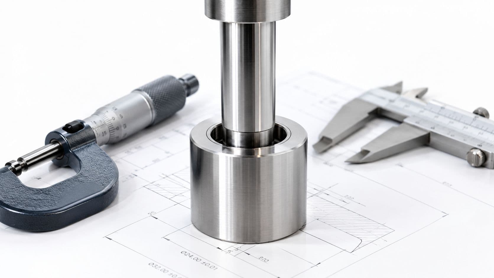
A hardened die plate lands on your desk with an internal profile that an end mill can't reach. The material is already heat treated, the corners need to stay sharp, and the drawing leaves little room for a “close enough” interpretation. Milling will either deflect, wear, or leave a radius where the tool cannot physically fit.
That's the situation where wire erosion cutting, usually called wire EDM, earns its place. It removes conductive metal without mechanical contact, follows complex two-dimensional profiles, and can finish a cut through multiple controlled passes. The important question, however, isn't whether wire EDM can cut the part. It usually can. The better question is whether it's worth choosing over milling, laser cutting, or waterjet for the specific combination of geometry, thickness, tolerance, finish, and production volume.
Table of Contents
- Introduction to Wire Erosion Cutting
- How Wire EDM Actually Works
The cutting sequence
Why hardness isn't the deciding material property
Tolerances and Surface Finishes You Can Achieve- Finish depends on energy, not just patience
Design Rules and Process Constraints- Review the model before requesting a quote
Wire EDM versus Laser Waterjet and CNC Milling- Use a decision matrix, not a slogan
Process Parameters and Quality Control- Stabilize the wire before chasing the tolerance
Prototyping Low-Volume Production Costs and Lead Times- What drives the quote
Introduction to Wire Erosion Cutting
Wire EDM is most useful when the part's functional requirements make ordinary cutting tools a poor fit. Hardened tool steel, carbide, titanium, and other difficult materials are within its practical range because the process removes metal through electrical discharges rather than cutting force. The workpiece still needs to be electrically conductive, and the geometry usually needs to suit a through-profile process.
The technology developed from experimental electrical-discharge work in the 1940s into industrial wire-cut machines in the 1960s. The first commercially available NC wire-cut EDM machine was reported in 1967, followed by an industrially significant NC wire EDM machine in 1969. Historical cutting rates moved from roughly 1 to 2 square inches per hour in the early 1970s to approximately 28 to 30 square inches per hour by the mid-1990s, an order-of-magnitude productivity improvement over that period, as documented in the historical overview of wire EDM development.
That history matters because wire EDM isn't a laboratory curiosity or a process reserved for one-off toolmaking. It's a mature precision method, but it remains selective. A simple profile in thin sheet may be far cheaper to laser cut. A pocket with generous access may be faster to mill. A thick, rough-cut structural plate may favor waterjet.
This guide focuses on that decision threshold. It covers how the process works, what tolerance and finish specifications are realistic, how thickness and cut length affect the result, and how to plan inspection for prototypes and low-volume production. It also gives a practical comparison with laser, waterjet, and CNC milling, so a design team can choose the process before committing to an unsuitable drawing.
How Wire EDM Actually Works
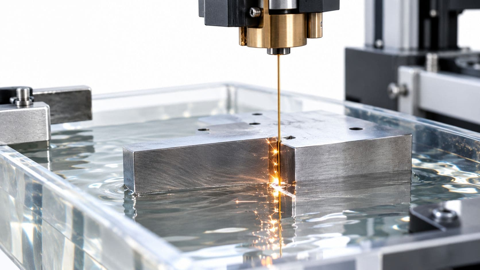
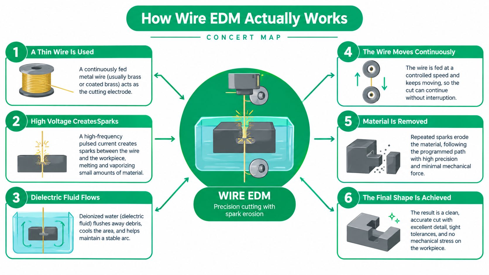
Wire EDM is a controlled spark-erosion process. A continuously fed wire electrode travels through the workpiece without touching it. Electrical discharges jump across a small gap between the wire and the conductive metal, and each discharge removes a microscopic amount of material.
The easiest analogy is a bandsaw that never makes contact with the part. The wire establishes the path, but sparks do the cutting. Because the wire doesn't push against the workpiece, the process avoids the cutting forces that cause tool deflection, burr formation, and distortion in many conventional operations.
The cutting sequence
The machine combines several systems to make that controlled erosion stable:
- The wire electrode travels continuously. Brass wire is common, although the exact wire selection depends on the machine, material, accuracy target, and cutting conditions. Fresh wire enters the cutting zone while used wire exits, so the electrode remains available for ongoing discharges.
- The workpiece sits in dielectric fluid. In many wire EDM machines, deionized water surrounds the cut. The fluid insulates the gap between discharges, carries away heat, and transports eroded particles out of the kerf.
- The CNC system moves the wire along the programmed profile. The machine controls motion in fine increments. One technical reference reports increments as small as 40 millionths of an inch, or 0.00004 inch and 0.001 mm, with some systems reaching 10 millionths of an inch, or 0.00001 inch, as described in the technical EDM handbook.
- The spark gap defines the active cutting zone. The wire has a physical diameter, but the electrical discharge extends beyond its surface. The resulting kerf is therefore wider than the wire itself. The CNC controller compensates for that offset when it calculates the path.
- Flushing nozzles remove debris. Eroded particles must leave the gap. If debris remains trapped, it can cause unstable discharges, short circuits, wire breaks, poor surface quality, or dimensional drift. Nozzle position, fluid condition, and workpiece thickness all affect flushing performance.
- The machine repeats the path for finishing. A rough cut removes most of the material efficiently. One or more skim, or finish, passes then remove a smaller amount with lower-energy discharges. Those passes improve profile accuracy and surface condition rather than merely making the slot wider.
Why hardness isn't the deciding material property
Hardness has little bearing on whether the spark can erode the material. Conductivity is the fundamental requirement. Hardened steel can be an excellent wire EDM candidate, while a nonconductive ceramic or plastic generally cannot be cut by standard wire EDM.
The absence of mechanical contact also explains why the process is effective for delicate profiles and heat-treated parts. It doesn't eliminate thermal effects, and it doesn't make every cut economical. It changes the dominant constraints from tool strength and access to conductivity, flushing, spark stability, and machine control.
Tolerances and Surface Finishes You Can Achieve
A wire EDM quotation should never promise a tolerance without tying it to thickness, cut length, geometry, datum strategy, and finishing passes. Machine motion resolution can be extremely fine, but resolution isn't the same as finished-part accuracy.
A technical source reports standard wire EDM accuracy around ±0.0005 inch, or ±0.0127 mm, while high-precision setups can reach approximately ±0.0001 inch, or 2.5 µm. The same body of technical material places EDM's share of the machine-tool market at about 0.5% in 1960 and approximately 6% by 1998, reflecting its development into a major precision process, as detailed in the EDM reference handbook.
Finish depends on energy, not just patience
Surface roughness changes substantially with discharge settings. One study reported a best roughness of about Ra 0.7 µm under standard finishing conditions, then achieved Ra 0.22 µm after tuning pulse and voltage-related parameters with Taguchi and ANOVA methods. The wire EDM surface-quality study identifies machining voltage, current-limiting resistance, pulse-generation circuit type, and capacitance as dominant variables.
That result has a practical implication. Don't specify a very fine finish and assume the machine will reach it through one aggressive pass. Lower-energy finishing passes are the practical route to finer surfaces, and those passes add time. A drawing that calls for a fine finish on every profile should be reviewed as a cost and function decision, not treated as a default quality requirement.
The table below gives a planning framework. These are engineering expectations rather than universal guarantees, and the tolerance and finish ranges should be confirmed against the supplier's machine, material, thickness, and inspection method. For general surface-finish terminology, consult this surface roughness chart.
| Cut Type | Typical Tolerance | Typical Surface Finish | Relative Speed |
|---|---|---|---|
| Rough profile cut | Broadest practical band, set by stock, thickness, and geometry | Coarser electrical-discharge texture | Fastest |
| Rough cut with one skim pass | Tighter profile control than a rough cut alone | Improved functional finish | Moderate |
| Precision profile with multiple skim passes | Near the machine and setup capability, often approaching ±0.0001 inch in a high-precision setup | Fine finish, with studies reaching Ra 0.22 µm after parameter tuning | Slow |
| Critical finish profile | Requires supplier-specific capability confirmation and controlled inspection | Fine surface suitable for demanding contact or fit requirements | Slowest |
Surface integrity needs its own specification
A wire EDM surface can contain a thin recast, or white, layer created by rapid localized heating and cooling. That layer may matter in tool and die, aerospace, and medical applications where fatigue behavior, cleanliness, or downstream coating performance is important.
If the functional surface will experience repeated loading, sliding contact, or fatigue, ask the supplier how the recast layer will be controlled and inspected. A secondary cleaning or finishing operation may be appropriate. Don't hide that requirement in a general note. Put the affected surfaces, roughness target, recast-layer expectation, and inspection method directly into the manufacturing documentation.
Design Rules and Process Constraints
Wire EDM works best when the CAD model reflects the way the machine enters, flushes, and finishes the cut. The design may look like a simple two-dimensional profile, but several small decisions determine whether the job is straightforward or expensive.
Review the model before requesting a quote
- Plan the start hole. A closed internal profile generally needs a starter hole so the wire can be threaded through the workpiece. Place it in a region that will be removed, hidden, or machined later. If the part has no suitable entry location, discuss a drilling operation before releasing the wire path.
- Account for kerf and offset. The finished opening is produced by the wire diameter plus the discharge gap. The CAM system normally compensates for this, but the drawing should still identify the functional profile and datum scheme clearly. Avoid manually shrinking geometry unless the supplier has specifically requested compensated geometry.
- Check internal corners. Wire EDM can produce sharper internal corners than rotating milling tools because the wire is not constrained by an end mill's profile. The corner still follows the wire diameter, spark gap, control behavior, and finishing strategy. If a corner is functionally critical, show its required radius rather than assuming “sharp” means zero radius.
- Use taper deliberately. The upper and lower wire guides can follow different coordinates, allowing tapered walls. Taper is useful for punches, dies, and mating components, but it also increases verification demands. Call out the intended angle and the reference surfaces.
- Flag thick sections early. As workpiece thickness increases, flushing and spark stability become harder. Wire lag, taper, slower cutting, and flush-related accuracy loss become more significant. One industry discussion reports that a thickness change from 1 inch to 4 inches can reduce cutting speed by about 60%, so the supplier needs thickness information before quoting, as explained in this wire EDM machining guide.
Cut length matters more than the envelope
A large blank with a short profile may be a simpler job than a small plate with a long, intricate perimeter. Every additional millimeter of cut length extends machine time, consumes wire, and may require the machine to negotiate more corners or narrow passages. Finish passes magnify that effect because they repeat the same path at lower energy.
Features such as mounting holes, shallow pockets, threads, and broad planar faces may be better handled by drilling or milling before or after the wire operation. A practical hybrid sequence is often more economical: mill the stock and reference datums, drill the starter hole, wire-cut the hardened internal profile, then perform any cleaning or surface treatment required by the application.
Practical rule: Design the wire EDM operation around the profile that only wire EDM can do. Don't send every easy feature to the wire machine.
Before releasing the model, confirm the following:
- Material is electrically conductive and its heat-treatment condition is known.
- Workpiece thickness is stated at the cut, not only in the stock description.
- Starter-hole locations are accessible and acceptable.
- Critical corners, taper, and mating surfaces are identified.
- Required roughness is limited to functional surfaces.
- Recast-layer requirements are defined where service performance depends on them.
- Inspection datums match how the part will function in the assembly.
Wire EDM versus Laser Waterjet and CNC Milling
Process selection becomes clearer when the team stops asking which technology has the longest capability list. The useful question is which process reaches the required result with the fewest compromises.
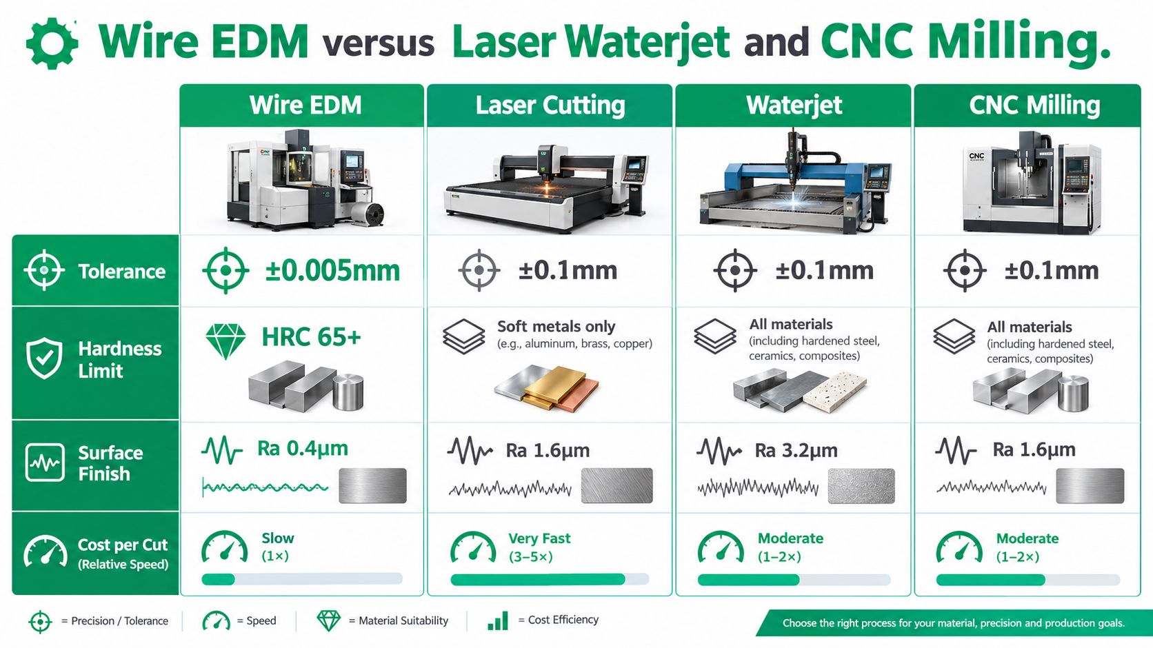
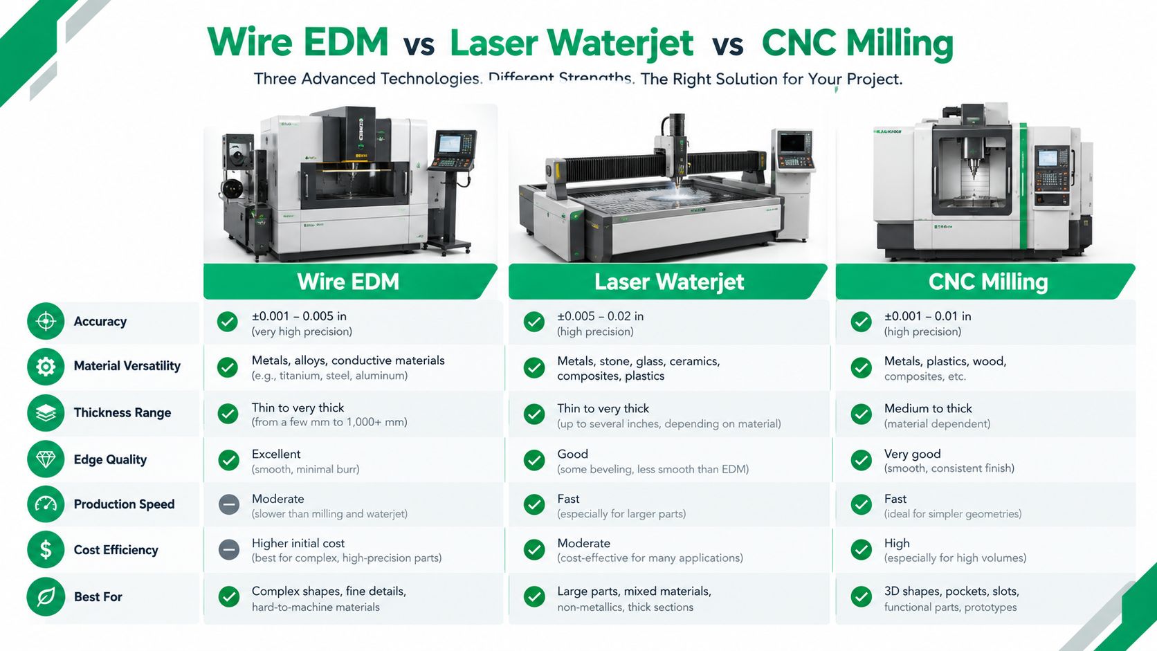
Laser cutting wins on speed for thin sheet profiles, especially when the material is easy to process and the tolerance is moderate. It's usually a poor substitute for wire EDM when the job involves hardened tool steel, delicate internal geometry, or demanding surface integrity. Laser heat input and edge condition also need review when the cut edge becomes a functional surface.
Waterjet handles a broad material range and avoids the same concentrated thermal mechanism as laser cutting, making it useful for thick plate, composites, and rough blanks. Its edge quality and dimensional control are generally less suitable for a precision mating profile that needs a fine finish. Waterjet is often a strong first operation, followed by milling or EDM where the functional geometry demands it.
CNC milling is the default for accessible geometry. It removes material efficiently, supports pockets and three-dimensional surfaces, and is usually the better economic choice for simple shapes and larger production volumes. A rotating cutter can't reach every internal corner, however, and hardened material can increase tool wear, cycle time, and risk. The fundamentals of choosing milling operations are outlined in this guide to the CNC machining process.
Use a decision matrix, not a slogan
| Requirement | Wire EDM | Laser | Waterjet | CNC milling |
|---|---|---|---|---|
| Conductive hard material | Strong fit | Application dependent | Generally broad material compatibility | Tool and machine dependent |
| Fine internal profile | Strong fit | Possible, with edge and heat review | Often needs secondary work | Limited by tool access and cutter radius |
| Thin sheet throughput | Usually not the first choice | Strong fit | Possible, but may be slower or less economical | Often inefficient |
| Thick workpiece | Feasible, but flushing and accuracy require review | Process dependent | Strong rough-cut candidate | Feasible where tool access is adequate |
| Three-dimensional pocketing | Limited as a through-profile process | Limited | Limited | Strong fit |
| High-volume simple profile | Often difficult to justify | Strong candidate | Depends on material and tolerance | Strong candidate |
| Hardened precision die profile | Strong fit | Usually not the first choice | Usually a roughing option | Often limited by access and tool wear |
The trade-off threshold is therefore four-dimensional. Geometry favors wire EDM when the profile is intricate, internal, and predominantly through-cut. Thickness penalizes it when flushing becomes difficult. Volume favors faster processes when the same simple shape repeats. Tolerance and finish can reverse the decision when a secondary operation would otherwise erase the initial savings.
Wire EDM is worth the premium when it removes a difficult operation, protects a critical profile, or lets you cut after heat treatment without mechanical distortion. It's the wrong choice when it's being used only because it can achieve a capability the part doesn't need.
Process Parameters and Quality Control
A wire EDM process plan should connect every major machine setting to an inspection result. “The machine is accurate” isn't a quality plan. The result depends on discharge energy, motion, wire behavior, flushing, dielectric condition, thickness, and the number of passes.
Pulse time, discharge current, and travel speed govern the balance between removal rate and surface quality. A rough cut can prioritize productivity, while skim passes reduce the energy applied to the finished wall. The wire EDM optimization study reports that parameter changes improved material removal rate by up to 15%, reduced roughness by about 20%, and reduced kerf width by around 10% in the studied conditions.
Stabilize the wire before chasing the tolerance
Wire tension and wire speed affect wire vibration, deflection, and kerf consistency. The same study reports wire tension in the 5 to 20 N range and wire speed around 4 to 17 m/min as conditions associated with stabilization and a kerf-width reduction of roughly 10% to 15% in the investigated process.
Those values aren't universal machine settings. They're useful starting points for a process discussion. The supplier should tune them against the material, thickness, wire type, flushing arrangement, and required profile.
Common failures have identifiable causes:
- Wire breakage often points to unstable discharge conditions, poor debris removal, excessive energy, or difficult flushing. Reduce the stress on the gap and verify fluid flow before restarting the cut.
- Taper and wire lag become more likely when the workpiece is thick, the wire is unstable, or the upper and lower guides don't maintain the intended path.
- Poor surface finish usually requires lower-energy finishing conditions, cleaner dielectric fluid, or additional skim passes.
- Thermal and recast concerns require a controlled finishing strategy and, for demanding applications, a defined cleaning or post-processing step.
- Dimensional drift can result from temperature, machine condition, datum errors, or debris trapped in the cut. Inspect the process, not only the final part.
Build an inspection plan around function
For a prototype, inspect the critical profile, thickness-related taper, corner geometry, and surface roughness. For production, add documented machine condition, material traceability, setup records, and repeatable datum control. A coordinate measuring machine can verify the profile against the drawing, while a calibrated roughness instrument can verify Ra on the specified surfaces.
Recast-layer inspection may require metallographic examination or an agreed supplier method when the part operates under fatigue, sliding contact, or biological-performance constraints. Don't demand a measurement that nobody has defined. State the acceptance criterion, the sampling plan, and the report format before cutting begins.
A profile can meet its nominal dimensions and still fail in service if the surface layer, taper, or edge condition wasn't part of the original quality decision.
Prototyping Low-Volume Production Costs and Lead Times
Wire EDM earns its keep in prototyping and low-volume production when the difficult feature is also the feature that defines the part's function. A hardened die insert with a complex opening, a carbide tooling component, a titanium medical profile, or a thin-wall conductive part with sharp internal transitions can justify the process even when a faster machine exists for simpler work.
The cost calculation starts with cut length, not only the outside dimensions. A long perimeter, multiple internal windows, narrow slots, and repeated skim passes all increase machine hours. Thickness adds another penalty because the wire must maintain a stable discharge path while flushing debris through a deeper kerf.
What drives the quote
- Profile length: The machine follows every contour. Long or highly detailed paths consume more time than a compact profile with the same overall envelope.
- Workpiece thickness: Thick cuts can slow dramatically as flushing and spark stability deteriorate. The supplier needs the actual cut height, including local bosses and steps.
- Finish strategy: Rough cuts are faster than finish cuts. A fine wall finish or tight profile may require several skim passes, and those passes can dominate the total cycle.
- Material condition: Conductivity, hardness, heat treatment, and carbide content influence cutting stability and parameter selection.
- Starter and secondary operations: Drilling a start hole, milling reference faces, removing tabs, cleaning the recast layer, and inspecting the profile may all be separate cost items.
- Quantity and nesting: A small batch can share setup and inspection work, but repetitive simple profiles may favor laser or milling once volume rises.
A prototype quote should therefore include the model, material grade and condition, stock size, finished thickness, profile tolerance, roughness requirement, starter-hole preference, and inspection expectations. If the supplier only receives a DXF with no functional datums, the quote may be fast but the process assumptions will remain unclear.
For early builds, a combined supplier can reduce handoffs when the part needs milling, drilling, wire EDM, surface treatment, and inspection in sequence. FIRMFG provides CNC machining, including wire EDM, alongside prototyping and low-volume manufacturing workflows, so a design team can ask for a process recommendation rather than sending the profile operation to an unrelated vendor. The broader economics of prototype planning are also discussed in this guide to rapid prototyping cost.
When wire EDM is the sensible choice
Choose wire erosion cutting when:
- The profile is conductive, difficult to access, or already hardened.
- Sharp internal geometry matters more than raw cutting speed.
- The required tolerance or finish would force expensive secondary work after laser or waterjet cutting.
- The quantity is low enough that specialized tooling for another process isn't justified.
- A through-profile is the critical feature and milling would require small tools, multiple setups, or unacceptable corner radii.
- The inspection plan can account for thickness, taper, finish, and surface integrity.
Choose another process when the profile is simple, the material is thin and easy to cut, the quantity rewards high throughput, or the geometry is primarily three-dimensional and accessible to a milling cutter. Waterjet may be the right roughing operation for thick stock, while milling can finish datums and non-profile features before wire EDM completes the hard internal contour.
Before requesting a quote, send the supplier a marked-up drawing and answer five questions: What surface controls the part? What profile is functionally critical? What thickness must the wire cut? Which surfaces need a fine finish? What evidence must accompany delivery? Those answers turn wire EDM from a generic capability into a controlled manufacturing decision.
For a hardened or intricate conductive profile, ask FIRMFG to review the CAD model, thickness, tolerance, finish, and inspection requirements before production. Visit FIRMFG to discuss a wire EDM route alongside CNC machining, prototyping, and low-volume manufacturing.