3 Axis vs 5 Axis CNC: Cost, Setup and Accuracy Compared
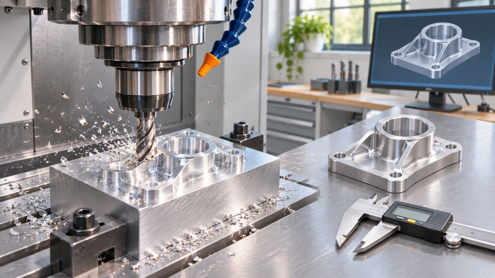
The part on your screen has a pocket on top, two bores on the front face, and one port sitting at 30 degrees off the side. The RFQ form has a dropdown for process, and you already suspect that clicking 5-axis adds money to the quote. What you don't know is whether that money buys anything the drawing needs.
Here's the reframe that settles it. A 5-axis machine isn't a better 3-axis machine. It's a different setup strategy. The decision comes down to how many orientations the cutter needs to reach your features, and how many times the part has to be unclamped and re-datumed to get there. Cost, tolerance stack-up, surface finish and lead time all follow from that one number.
So treat the 3 axis vs 5 axis CNC question as an access problem with a price tag, not a horsepower contest. The sections below work through it in the order a shop does: geometry first, then setups, then money, then accuracy.
Table of Contents
- 3-Axis and 5-Axis CNC Side by Side
- How Each Axis Count Moves the Cutter
- Which Geometry Needs Which Axis Count
- Setup Count and Cycle Time Drive the Cost Gap
- Accuracy Depends on More Than Axis Count
- How Lead Time Changes With Axis Count
- Choose the Axis Count and Send the Brief
3-Axis and 5-Axis CNC Side by Side
Two quotes come back for the same aluminum bracket. One is nearly half again the price of the other, and the only thing that changed is the machine assigned to the job. That bracket has pads on opposite faces and two holes drilled at 15 degrees, so one shop quoted three separate fixturings on a 3-axis mill and the other quoted a single 5-axis job.
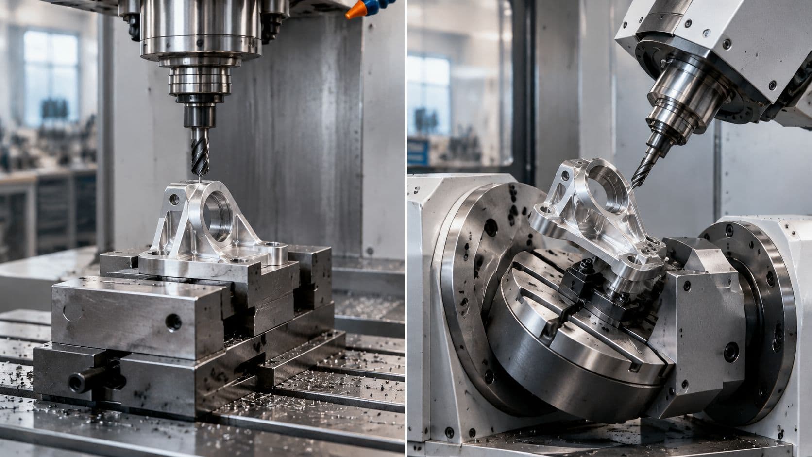
The mechanical difference is small on paper. 3-axis machining drives the cutter along X, Y and Z with the tool pointing the same way the whole time, so any face the tool can't see has to be rotated into view by hand. 5-axis machining coordinates those three linear axes with two rotary axes, reorienting the part or the spindle so the cutter reaches several faces while the part stays clamped. A study in Scientific Reports describes that single-clamping capability as reducing interference and improving surface quality compared with traditional three-axis work.
| Aspect | 3-Axis CNC | 5-Axis CNC |
|---|---|---|
| Axes controlled | X, Y, Z linear motion | X, Y, Z plus two rotary axes |
| Tool approach | Fixed direction, usually from the top | Tool can approach from multiple orientations |
| Best-fit geometry | Prismatic parts, pockets, slots, flat faces | Compound angles, undercuts, deep cavities, organic surfaces |
| Re-clamping on multi-face parts | Frequent manual flips and re-fixturing | Reduced, often to one or two clampings |
| Programming effort | Simpler CAM and toolpaths | Requires 5-axis CAM and careful postprocessing |
| Machine complexity and cost | Lower capital and hourly rate | Higher capital, calibration and hourly rate |
| Main accuracy risk | Setup-dependent error between faces | Rotary calibration, fixture rigidity and thermal drift |
Read rows two and three first. If every feature on the drawing is reachable from the top, 3-axis is the default and the extra axes add cost without adding access. The moment features sit on three or more faces, or a bore runs at a compound angle, re-clamping becomes the dominant cost line and the right-hand column starts earning its rate.
The last row is the one worth arguing about with a supplier. The accuracy risk in each column is a process risk, not a spec, and neither machine ships with a guaranteed part tolerance stamped on the side.
For a straightforward bracket, this table answers the question on its own. The judgement calls start where the rows overlap, when a part has one awkward face rather than five.
How Each Axis Count Moves the Cutter
Three modes, not two. That's the part most comparisons skip.
Fixed orientation. On a plain 3-axis mill the tool vector never changes. Every new face is a new setup: unclamp, brush the chips, re-datum, indicate the part in, touch off the tools, cut. On a component with features on five sides, that cycle repeats four or five times, and each repeat is another chance for the part to land fractionally differently in the vise.
Indexed tilt. 3+2 machining, also called positional five-axis, uses the rotary axes only between cuts. The table tilts to a new angle, the rotaries clamp, and the cutting itself is ordinary three-axis motion in that new orientation. The angled face gets machined without a custom fixture, and the CAM work is a set of three-axis toolpaths assigned to workplanes rather than one synchronized five-axis path.
Continuous motion. Simultaneous five-axis keeps all five axes moving during the cut. It earns its keep when the contact angle has to stay constant across a sculpted surface, or when a short, rigid tool has to reach into a deep cavity at an angle instead of hanging out of the holder like a diving board.
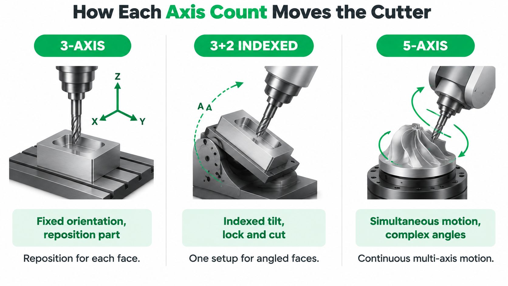
The number that matters isn't five. It's the count of distinct orientations your part needs. Four orientations is a 3+2 job, not a simultaneous five-axis job, and quoting it as the latter inflates programming hours for nothing.
The insight worth carrying into a supplier conversation is that 3+2 removes most of the re-clamping at a fraction of the programming cost. Full simultaneous work is for continuous surfaces, not for a part that merely has holes on four sides. You can see how that fits the wider CNC machining process from stock to finished part, where setup planning sits ahead of toolpath strategy.
Before you approve a quote, ask one question about each face: which mode will run it, indexed or simultaneous? A vague answer usually means the CAM programmer hasn't looked at the part yet.
Which Geometry Needs Which Axis Count
Start at the top face. Open the model in the orientation it would sit on the table and ask what the cutter can see. Most parts that can be finished from one direction never leave the 3-axis column, and that's the cheapest place for a design to live.
Then work down the feature list from simple to awkward:
| Feature or condition | Axis approach | Why it matters |
|---|---|---|
| Pockets, slots and holes on a top face | 3-axis | Full access from one direction |
| Several flat faces needing positional accuracy | 3+2 indexed or 4-axis | Rotary index reduces re-clamping between faces |
| Angled bores or compound angles | 3+2 indexed or 5-axis | Tool orientation reaches the angle without a custom fixture |
| Undercuts | 4-axis or 5-axis | Side or angled tool access that a top-down cutter cannot reach |
| Deep cavities, molds and impeller-like features | Simultaneous 5-axis | Continuous tool orientation avoids collisions and allows shorter tools |
| Organic or sculpted surfaces | Simultaneous 5-axis | Maintains a favorable contact angle for a smooth finish |
The re-clamping row is where the arithmetic gets uncomfortable. On a five-face component, a 3-axis process commonly needs about 4 to 5 setups, indexed 3+2 work usually brings that down to 1 to 2, and simultaneous five-axis often finishes the part in one clamping (Uptool 5-axis mill guide). Those extra clampings don't just cost time. Every one of them transfers the datum again.
We keep all three modes under one roof, so the recommendation doesn't have to bend toward whatever machine is free: 3-axis CNC milling for simple to moderate complexity parts, 4-axis for complex geometry and undercuts where a single rotary index solves access, and full simultaneous 5-axis for the parts that need continuous orientation.
Borderline cases are worth a second look before you accept a 5-axis price. A part with one angled pad can often be redesigned with a split line, a standardized hole direction, or a flat that gives the 3-axis cutter clearance. Changing the drawing is usually cheaper than changing the process.
Working rule: if every feature is reachable from one or two orientations, 3-axis or 3+2 is enough. Reserve simultaneous five-axis for geometry that changes direction continuously.
Setup Count and Cycle Time Drive the Cost Gap
Each setup is a cost event, not a machine-hour event. When a part comes off the table, someone unclamps it, cleans the locating faces, re-datums it, touches off tools again and proves the first article before the next face runs. That labor is billed whether the spindle turns or not, and on a multi-face part it repeats for every orientation.
This is also why an extra setup can raise part cost by roughly 30% to 60%, depending on complexity, as a neutral DFM comparison notes while separating indexed five-axis work from continuous simultaneous cutting (Misumi manufacturing DFM comparison). Setup count is the first lever to pull, before toolpath optimization, before coolant strategy, before anything else on the process sheet.
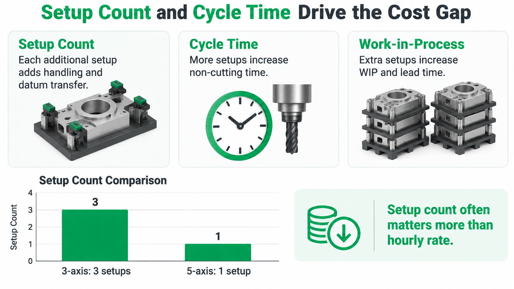
The published comparison numbers follow the same logic. A 2024 industrial white paper reported setups falling from more than five on a three-axis process to two on a five-axis process, a reduction of at least 60%, with total tooling dropping from 17 tools to 8, roughly 53% fewer (DMG Mori 5-axis white paper). Treat those as one application's result, not an average. Material, feature access, tolerances, tool strategy, workholding, programming hours and batch size all move the outcome.
The counter-case is just as real. For a simple prismatic part, a 3-axis process is usually cheaper, because it needs less CAM time and sits on a less expensive machine. Paying a five-axis rate for a plate with six holes in it buys nothing.
Cost rule: compare quotes on machine time plus programming plus handling per setup. The hourly rate alone will steer you wrong every time on a multi-face part.
That comparison only works if the shop can offer the mode each part deserves. With more than 100 CNC machines on the floor, including 3-axis, 4-axis and 5-axis machining centers, the setup plan can follow the geometry rather than the availability chart. For a deeper look at how programming and fixturing land in the price, see this breakdown of CNC milling cost.
Accuracy Depends on More Than Axis Count
A 5-axis machine does not automatically hold a tighter tolerance than a 3-axis machine. It removes one specific error source, the re-clamp, and it improves tool orientation on contoured surfaces. Everything else in the error budget stays where it was, and a few new terms get added.
The setup logic explains most of the difference. A 3-axis part gets re-clamped for each new face, so positional error accumulates between features cut in different setups. A 3+2 or full 5-axis process reaches more of those features in one clamping, and less of that stack-up reaches the part. One published mold-making comparison reported 0.0213 mm average error on complex surfaces, 0.723 micrometer surface roughness and a 1.47-times efficiency improvement after tool-axis optimization (5-axis mold-making process comparison). Those numbers describe specific machines, fixtures, cutters, materials and toolpaths. Read them as evidence of what is achievable rather than a purchase specification.
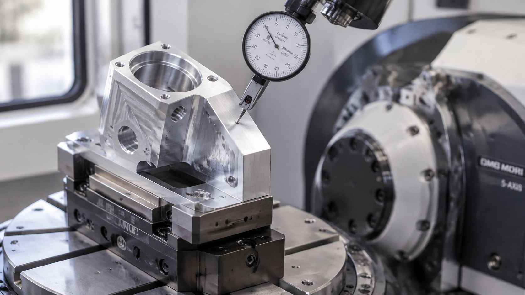
The mechanism matters more than the number. Fewer clampings mean fewer datum transfers and less stack-up between features that must hold position relative to each other. Shorter tools and better orientation reach drafted or sculpted surfaces without chatter. Indexed 3+2 work captures most of this gain: the rotary axes lock at a fixed angle, the cutter works like a stiff 3-axis setup, and the simultaneous-motion error terms never enter the budget. What erodes the advantage is mundane:
- Rotary-axis calibration: a slightly off trunnion tilts every subsequent feature.
- Volumetric error and thermal drift: the machine moves as it warms, and five axes compound it.
- Postprocessor quality: a post that misinterprets kinematics produces gouges instead of parts.
- Collision avoidance: more axes mean more ways to crash, and simulation is not optional.
- Fixture rigidity: a tall angled setup can deflect under load regardless of axis count.
Ask for proof on the actual geometry rather than the axis count. Request the datum strategy, true-position results on the finished part, surface-finish measurements and process capability data before you sign off on a first article.
That request is verifiable rather than aspirational. Capability across our processes holds tolerances as tight as ±0.0005 inch, and dimensional inspection uses a CMM and calibrated digital calipers with results documented against CAD nominal values. How those limits are set and checked is covered in the guide to CNC machining tolerances.
How Lead Time Changes With Axis Count
Lead time is a scheduling question before it's a machining question. Four things move it: setup count, since each clamping adds a queue step and often an inspection hold; CAM and postprocessing hours that happen before the first chip; tool and fixture preparation; and batch size, which decides whether programming time is spread over one part or fifty.
The three modes behave differently on the calendar.
- 3-axis, short programming, long queue. CAM is quick and predictable, but a part with five faces waits through four or more setups, each with its own slot in the schedule.
- 3+2 indexed, the middle case. One or two setups cover the angled faces, with CAM work for those workplanes added up front. Most multi-face prototypes land here.
- Simultaneous 5-axis, one clamping, longest front end. Toolpath generation, simulation and postprocessing take the most hours, and the job may also queue behind limited five-axis capacity.
A five-axis quote with a long lead time is usually waiting on CAM, not on the spindle.
Cycle time is the one stage that shrinks. The same 2024 industrial white paper reported cycle time falling from 48 minutes to 33 minutes when a job moved from a three-axis process to a five-axis one, about 31%. That's the cutting stage only. Programming, fixturing and inspection sit outside it, which is why a one-off prototype can take longer on the five-axis machine even though a production run of the same part finishes sooner.
Ask for lead time split into programming, machining and inspection. When a prototype has to move, we deliver CNC machined parts in as fast as 3 days with rush service available, and it's worth confirming whether the rush covers the CAM hours or only the spindle.
Choose the Axis Count and Send the Brief
The verdict breaks three ways. Simple prismatic parts, and most prototypes with features on one or two faces, belong on 3-axis; check top-face access before you accept anything more expensive. Parts with several faces that need positional accuracy, or angled features a rotary index can reach, belong on 3+2 indexed, with the setup plan requested in writing. Continuous sculpted surfaces, deep cavities and geometry that needs the tool angle to change mid-cut belong on simultaneous 5-axis, and that quote should arrive with an inspection report.
From there, five steps take you to a brief a shop can price accurately.
- List every feature and the face it sits on. A simple table of feature, face and tolerance is enough, and it exposes the parts of the drawing that force extra setups.
- Mark only the critical dimensions. Tag the features that carry true position or a tight limit. Tolerancing everything tightly raises cost on features that never needed it.
- Pick the axis approach from the verdict above. If one angled face is the only obstacle, ask whether a split line, a changed hole direction or a rotary index removes it before you accept a five-axis rate.
- Upload the CAD files for a free quote within 24 hours. FIRMFG issues it with the axis approach attached, not just a dollar figure.
- Ask for setup count and inspection plan in the quote. Compare quotes on total cost per part, because the cheapest line item can carry the most rework when the setup plan is missing.
That last point is where most sourcing decisions go wrong. Two quotes for the same part aren't comparable unless both state how many setups they assume and how the critical features get verified. A low number built on an optimistic setup plan will come back as a change order.
What goes into the email is simple: the axis count you expect, the setup count you're assuming, and the inspection you need. Then let the shop argue with the assumptions rather than with the price.
FIRMFG machines prototypes and low-volume production parts across 3-axis, 4-axis and simultaneous 5-axis work, so the axis count follows your geometry rather than the machine that happens to be open. Send the drawing with the toleranced features marked and you'll get a quote that states the setup count and inspection plan alongside the price. Upload your CAD files at FIRMFG to get the free quote within 24 hours.