CNC Machining for Medical Devices: A Practical Guide
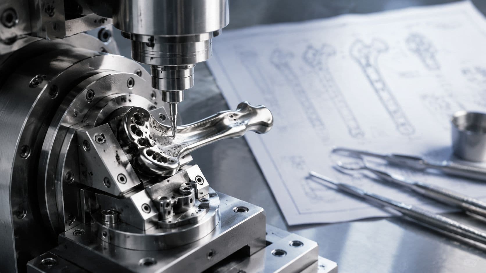
An R&D engineer at a Class II implant startup has six weeks to deliver 30 titanium trial components before a design freeze. The prototype shop rejects the drawings because one wall-thickness callout falls below 0.4 mm. The engineer now has to decide whether to redesign the feature, move from three-axis milling to a more capable process, accept a higher material cost, or risk a schedule slip that affects verification testing.
That decision is typical of CNC machining for medical devices. The machine must produce the geometry, but the supplier also has to prove what material was used, which program ran, how critical dimensions were inspected, and whether the finished surface suits its contact with tissue, fluid, or another component. A precise part without a credible evidence trail can still fail a design review or supplier audit.
The practical questions are therefore broader than tolerance alone. This guide connects axis selection, material choice, surface finish, DFM, inspection, validation, and regulatory documentation so engineers and buyers can make those decisions before releasing a drawing.
Table of Contents
Where CNC Fits Inside the Medical Device Market- Segment comparison
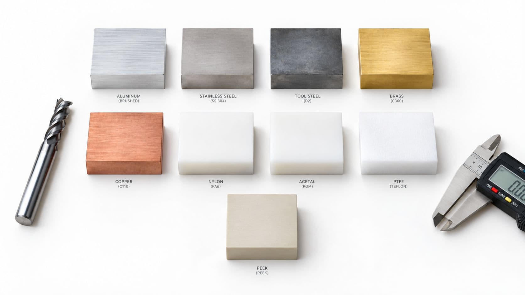
Choosing Metals and Plastics for Medical CNC Parts- Metals for instruments and implants
Tolerance Bands and Surface Finish Targets That Matter- Put GD&T where it controls function
ISO 13485, FDA, and the New Regulatory Baseline- Convert requirements into shop-floor records
DFM Tips for 3, 4, and 5-Axis Medical Machining- Three-axis work rewards simple orientation
Prototyping Versus Low-Volume Production Workflows- Match the build to the milestone
Selecting a CNC Partner and Controlling Cost- Short FAQ
Why Medical Device Engineers Care About CNC Machining Right Now
A surgeon's instrument can pass dimensional inspection and still fail its design review if the supplier cannot show material identity, inspection records, and the approved machining program. That is the practical pressure behind CNC machining for medical devices. The process must produce the geometry, while the quality system must preserve evidence that the released part matches the validated design.
For a buyer, this connects regulatory expectations to decisions made on the shop floor. A titanium implant may require controlled fixturing to prevent distortion, a polished interface may need a defined measurement method rather than a visual check, and a material substitution may require documented approval before production continues. The drawing starts the discussion, but the process plan and inspection record determine whether the part can support release.
The drawing is only the beginning
In a design-for-manufacturing review, I separate the questions into four groups:
- Can the machine reach the feature? A three-axis setup may suit a prismatic housing. A four-axis or five-axis process can reduce repositioning and alignment risk on a multi-sided implant. The choice affects datum control, setup documentation, and inspection strategy.
- Can the material survive the process? Titanium, stainless steel, cobalt-chrome alloys, and engineering polymers need different tooling, coolant, fixturing, and finishing choices. Those settings should be controlled in the approved process, not left to informal operator preference.
- Does the surface perform its intended function? A bearing surface, bone-contacting surface, and surgical-instrument grip should not receive the same finish because they belong to one part. The drawing should connect each finish requirement to its functional or biological purpose.
- Can the supplier prove conformity? Material certificates, inspection results, nonconformance records, and revision-controlled programs create the evidence needed for an ISO 13485 quality system and FDA-facing device records.
CNC machining became a practical foundation for medical-device production after the first CNC machine prototype was developed at MIT in 1952. Commercial adoption accelerated through the late 1960s and became standard for large-volume manufacturing by 1989, a history summarized in the medical devices machine tools market analysis. That progression matters because implants, surgical tools, and prosthetic components require repeatable production of complex geometry and controlled dimensions.
Practical rule: Treat every critical machining decision as both a production decision and a future audit question.
Where CNC Fits Inside the Medical Device Market
A medical design becomes a usable, inspectable component at the CNC machine. The same process may support design verification, specialized instruments, implant interfaces, diagnostic enclosures, and low-volume production before dedicated molding or casting equipment makes financial sense.
The market figures cited earlier describe demand for medical manufacturing equipment, not a standalone CNC-services revenue pool. For buyers, the practical implication is broader: suppliers must support more than cutting metal. They need repeatable setups, controlled inspection, material traceability, and records that connect the machined result to the approved design.
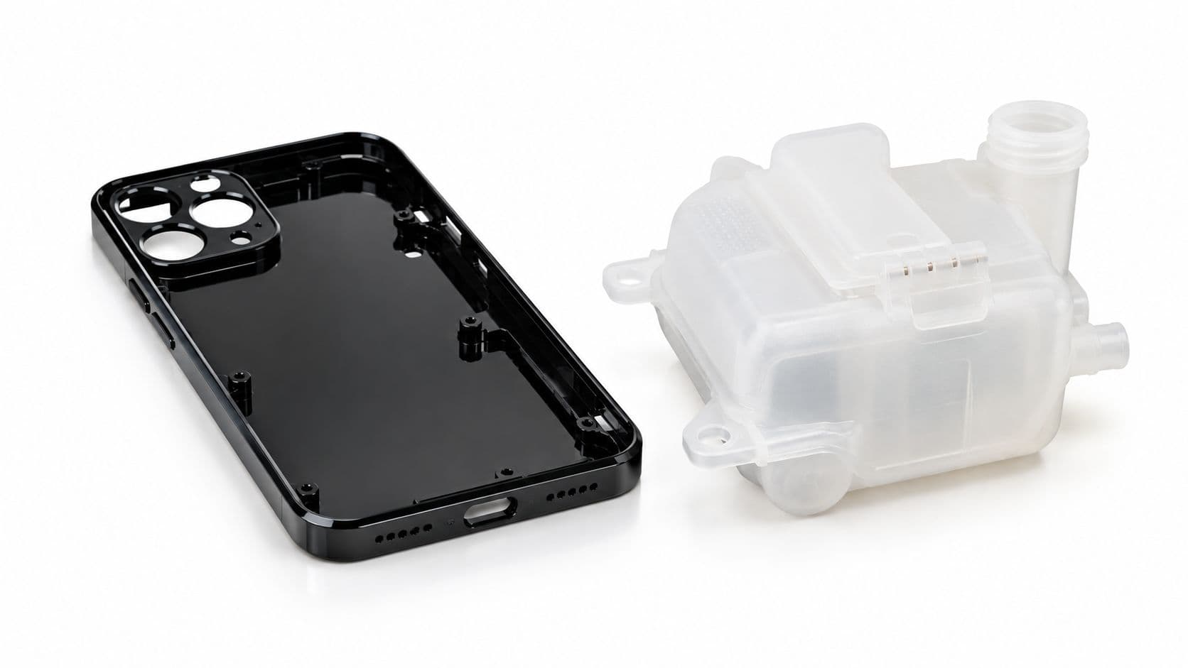
Orthopedic and spinal components often concentrate risk at interfaces, screw features, slots, and anatomical surfaces. Surgical instruments add ergonomic geometry, functional edges, pivots, jaws, and crevices that must tolerate cleaning and sterilization. Diagnostic housings and fluid-handling parts may appear simpler, yet sealing faces, bores, threads, and connector interfaces can carry comparable inspection requirements.
Product size also changes the manufacturing route. Endoscopic tools, catheter-related components, robotic instruments, and small diagnostic assemblies may call for Swiss turning, micro-machining, wire EDM, or five-axis milling instead of a general-purpose vertical machining center. A machine list alone does not establish capability. Review the supplier's tooling, workholding, metrology, simulation, and document-control practices against the actual geometry and inspection plan.
Segment comparison
| Segment | Typical CNC reliance | Common part type |
|---|---|---|
| Orthopedic implants | High | Bone screws, implant bodies, trial components |
| Spinal hardware | High | Cages, fixation components, graft windows |
| Surgical instruments | High | Handles, jaws, cutting tools, articulated parts |
| Diagnostic equipment | Moderate to high | Housings, brackets, sensor interfaces |
| Fluid-handling systems | Moderate to high | Manifolds, valves, precision bores |
CNC also gives engineering teams a controlled way to test a design before committing to later production methods. Machining can reveal fit problems, handling issues, leakage at seals, or sterilization-related access concerns while revisions remain practical. For an ISO 13485 or FDA-facing program, record those findings through revision-controlled drawings, inspection results, and approved change history rather than treating prototype feedback as informal shop knowledge.
The buyer should define which features must remain stable as the process changes. A machined prototype may transition to molded, cast, or near-net production, but its critical dimensions, acceptance criteria, and supporting records still need a clear handoff.
Choosing Metals and Plastics for Medical CNC Parts
A material review should start with the device's patient contact, mechanical load, sterilization route, and finishing plan. A grade that cuts cleanly may fail an implantation or cleaning requirement. An implant alloy may meet the clinical need yet increase tool wear, heat-control work, burr removal, and inspection time. Those trade-offs belong in the DFM review and quotation.
Metals for instruments and implants
316L stainless steel suits corrosion-resistant instruments, housings, and parts exposed to repeated cleaning or sterilization. 17-4 PH stainless steel provides higher strength for durable instrument bodies and housings, provided the supplier controls material condition, heat-treatment history, and identification. Request the material certificate, heat or lot identification, and applicable biocompatibility evidence for the finished device. An alloy name alone does not establish traceability or suitability.
Ti-6Al-4V ELI is often selected for load-bearing implants because it combines low density, strength, and established implant use. Its machining behavior affects both cost and validation. Heat concentration, tool wear, burr control, and workholding stability may require conservative cutting parameters and added inspection. CoCrMo fits high-wear joint-replacement applications, although its hardness and finishing requirements can increase cycle time and tool consumption. MP35N applies to high-stress cardiovascular components, where material certification and lot segregation need close control.
Finish requirements depend on the contact mode. Bearing, bone-contacting, and instrument surfaces each call for different targets. The full Ra ranges and their functional context appear in the finish specification table in section 4. The surface-finish guidance for medical CNC machining is useful during that review, but these values should not become automatic drawing defaults. The design team, quality engineer, and supplier must connect each target to friction, tissue contact, cleaning, wear, or handling.
Engineering plastics and evidence requirements
PEEK, PPSU, PEI, acetal, and PTFE can address weight, insulation, radiolucency, chemical resistance, or friction requirements. Select the exact medical grade, then request the certificate of conformance, resin lot information, sterilization compatibility data, and relevant biological evaluation records. USP Class VI or ISO 10993 status can support material selection, but it does not validate every geometry, surface condition, cleaning process, or patient-contact duration.
PEEK often suits radiolucent structural components and demanding chemical environments. PPSU and PEI can serve reusable equipment parts exposed to heat, subject to the selected grade and sterilization cycle. Acetal can work in non-implantable precision mechanisms. PTFE supports low-friction applications, but its tendency to deform under cutting forces requires careful fixturing. Ask the supplier how moisture conditioning, thermal expansion, and burr inspection will be reflected in the dimensional report.

Material selection is complete only when the grade, process controls, and records agree. A grade change may require a new drawing review, risk assessment, inspection plan, or validation rationale. Tie those changes to controlled documentation before production proceeds.
Tolerance Bands and Surface Finish Targets That Matter
A tolerance callout should follow the failure mode, not compensate for an unclear design. In a DFM review, identify the features that control fit, motion, sealing, fixation, or patient contact. Then specify how each feature will be measured and at what stage of production.
Industry guidance places typical medical CNC work around ±0.01 mm for linear and hole sizes, 0.02 mm true position, and 0.8 to 1.6 µm Ra. Validated high-precision builds can reach ±0.002 mm on critical features and ≤0.4 µm Ra after polishing or electropolishing, according to this medical manufacturing precision guide. Treat these figures as capability bands, not default drawing requirements. The supplier still has to show that the machine, fixture, inspection system, and finishing sequence can hold the specified result.
Put GD&T where it controls function
True position usually gives better assembly control than a group of unrelated coordinate dimensions when a screw pattern or connector array must align with its mating part. Profile controls can define a sealing face or anatomical contour. Concentricity or runout may be appropriate for rotating and mating cylindrical features.
Datum selection determines whether the inspection reflects real assembly conditions. If the datum does not match how the part locates in use, a report can show compliance while the assembled device binds, leaks, or sits out of position. Define the primary locating surfaces first, then build the inspection scheme around them.
Surface finish also needs a functional callout. A bearing surface may require low roughness to limit friction and wear. A bone-contacting area may need a different texture for fixation or tissue integration. A fluid-contacting bore needs a finish and lay that limit contamination risk while remaining practical to machine, clean, and verify.
Price the inspection and process burden before release
| Part category | Typical tolerance | Surface finish, Ra | Inspection method | Example application |
|---|---|---|---|---|
| General medical housing | ±0.01 mm | 0.8 to 1.6 µm | Calibrated hand tools, CMM as needed | Diagnostic enclosure |
| Instrument functional feature | Feature-specific | 0.4 to 0.8 µm | CMM and surface profilometer | Tool interface or pivot |
| Bone-contacting surface | Feature-specific | 1.0 to 3.2 µm | Profilometer and visual inspection | Non-bearing implant area |
| Bearing interface | Up to ±0.002 mm on critical features | 0.025 to 0.05 µm | CMM, profilometer, optical inspection | Implant bearing surface |
A tighter tolerance can require dedicated fixturing, temperature control, probing, calibrated CMM routines, and more frequent in-process checks. Polishing or electropolishing can improve roughness while shifting dimensions or rounding edges. Measure after the final process, and state that sequence in the inspection plan.
Measurement must follow the process sequence. If finishing changes the feature, the post-finish report is the report that matters.
ISO 13485, FDA, and the New Regulatory Baseline
A machined implant interface passes inspection, yet the supplier cannot show which material lot, program revision, or calibration record supported its release. The part may conform, but the manufacturing evidence is incomplete. ISO 13485 and FDA expectations connect those two outcomes: controlled production and objective records.
Before the first chip is cut, provide the current drawing revision, approved material specification, critical-characteristic list, risk information, and cleaning or finishing instructions. The supplier should show how each input becomes a router, inspection plan, traveler, and release record. For a practical buyer-side explanation, review ISO 13485 controls for medical devices.
Convert requirements into shop-floor records
Risk-based controls must alter the machining and inspection plan. An implant interface may require controlled fixturing, first-piece verification, in-process probing, and a final CMM report. A cosmetic enclosure can use a different inspection strategy. Ask the supplier to link each critical feature to its inspection frequency, acceptance criteria, and reaction plan.
DHF inputs need revision control. The machine shop may not own the complete design history file, but it can generate manufacturing drawings, approved deviations, first-article records, inspection results, material certificates, and finishing certificates. Those records support design verification and production documentation.
Lot traceability must continue through every operation. The traveler should connect the raw-material heat or resin lot, internal work order, machine-program revision, operator or inspector record, outside-processing certificate, and final shipment. Marking also requires review. If laser marking occurs before another operation, confirm that the identifier remains readable and does not affect a critical surface.
Supplier controls and corrective action require evidence, not a certificate alone. Request the supplier-qualification record, certificate status, calibration records for relevant instruments, nonconformance procedure, CAPA process, and a sample inspection package. FDA quality-system expectations also bring software and production records into review when digital systems control or document manufacturing.

Regulation is becoming more process-specific
China's revised Good Manufacturing Practice for Medical Devices was released in late 2025 and is scheduled to take effect on November 1, 2026, according to the National Medical Products Administration announcement. FDA guidance on computer software assurance for production and quality-management software was updated in May 2026, pointing to closer attention to digital traceability in manufacturing records. Qualifying a supplier on ISO 13485 certification alone leaves important process questions unanswered.
A connected inspection system, CNC program repository, or electronic traveler can support control. The manufacturer still needs to know who may revise records, how approvals are logged, and how obsolete revisions are blocked. The final evidence should connect the approved design to the released part without depending on informal email trails. That connection is what turns a conforming component into a defensible manufacturing record.
DFM Tips for 3, 4, and 5-Axis Medical Machining
Choose the axis configuration from feature access, datum control, and tolerance risk. A five-axis machine can reduce setups, yet its programming, simulation, and qualification burden may exceed that of a stable three-axis process. In a DFM review, the defensible choice is the process that controls the critical features and produces inspection evidence consistently.
Three-axis work rewards simple orientation
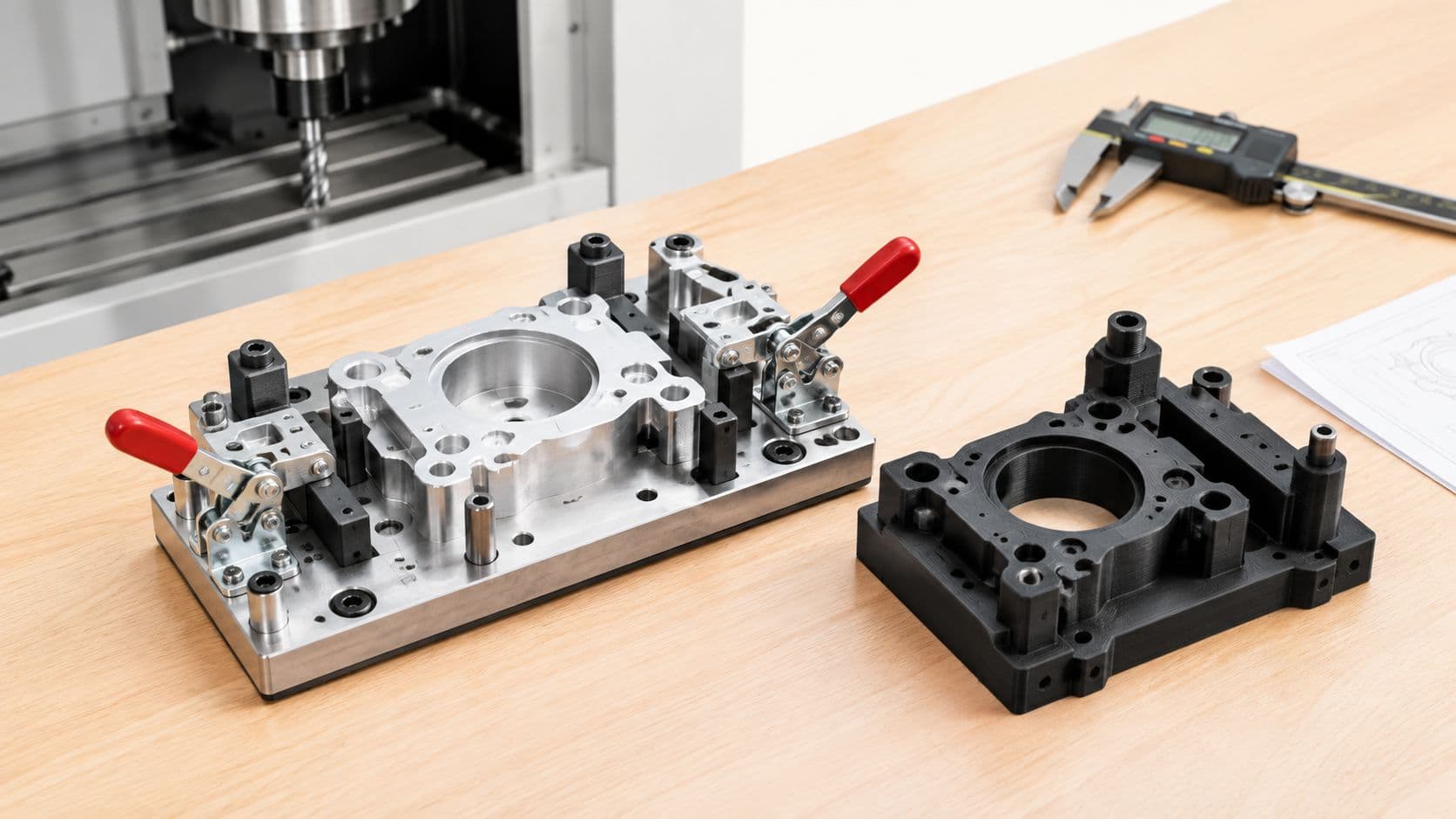
Three-axis milling suits parts whose important features are reachable from a limited set of controlled orientations. Orient the model to reduce setups, datum transfers, and opportunities for variation. That arrangement also makes first-article inspection easier because the inspection plan follows clearer reference surfaces.
Thin walls require a joint review of material, wall height, support, tool access, and cutting conditions. The supplied 0.5 mm guideline is a design cue for limiting chatter, not a universal acceptance limit. A rejected sub-0.4 mm prototype shows why wall thickness cannot be approved in isolation.
Deep pockets can deflect small tools and retain chips. Widen the cavity, add a cutter-compatible radius, or revise the relationship between the pocket floor and walls. The supplied DFM guidance recommends avoiding deep pockets narrower than three times tool diameter, but material, depth, tool stickout, coolant, and fixturing still determine whether the feature machines and inspects reliably.
Four-axis and Swiss work
Four-axis indexing helps with repeated or rotationally distributed features. A bone-screw driver body or pen-style drug-delivery housing may need fewer manual repositioning steps and better concentricity. Before release, the programmer should confirm rotary-axis clearance, clamp access, datum references, and the location and sequence of any marking.
Swiss-type turning supports small cylindrical medical pins close to the cutting zone. Live tooling can produce cross-holes, flats, and slots without transferring the part to a separate mill. The quotation and process review should account for guide-bushing setup, bar remnants, tooling, and inspection of slender features.
Five-axis access
Use five-axis machining when one setup protects a critical relationship that would otherwise accumulate across multiple datums. Spinal-cage graft windows, catheter-tip ports, and organic implant surfaces can benefit from controlled tool orientation and access. The supplier should simulate the toolpath, check collisions, verify tool reach, and define how the finished part will be inspected.
Geometry intended for sterilization also belongs in the DFM review. Avoid sharp internal corners that trap residue or hinder cleaning. Specify radii that support electropolishing or other finishing operations. Place traceability marks on nonfunctional surfaces, or control the marking sequence so every setup preserves the required identification.

For a closer examination of multi-sided access and setup reduction, review this five-axis CNC milling guide. The decision test is practical: five-axis machining should remove a tolerance stack-up, protect a surface, or make an inaccessible feature repeatable. If it does none of these, three-axis or indexed four-axis work may provide simpler qualification and stronger process evidence.
Prototyping Versus Low-Volume Production Workflows
A prototype that exposes fit and handling should move quickly. A batch used for verification and validation must also produce repeatable evidence. The workflow should match the decision the parts need to support, including machining, inspection, cleaning, marking, and records.
Match the build to the milestone
Prototype builds prioritize design learning. Soft jaws, a stable setup, probing, and a focused dimensional report can reveal interference, burrs, ergonomic problems, or assembly errors before design freeze. Keep revision control and material identity in the records. Limit inspection to design-critical characteristics unless the intended test requires more.
Bridge builds need stronger process definition. Dedicated fixtures, a formal inspection plan, first-article inspection aligned with AS9102 or an equivalent format, and controlled program revisions make the parts more useful for V&V testing. Repeated handling often exposes issues with cleaning, finishing, packaging, and marking that a single prototype will not show.
Low-volume production requires a qualified process, not a successful one-off. Use validated CNC programs, qualified workholding, calibrated CMM routines, batch traceability, and documented release criteria. The device-history record should connect each batch with its material, traveler, inspection data, finishing records, and approved deviations.
| Stage | Typical quantity | Workholding | Inspection | Documentation | Lead-time focus |
|---|---|---|---|---|---|
| Prototype | 1 to 25 units | Soft jaws, flexible fixtures | Critical dimensions, fit checks | Revision and material records | Fast learning |
| Bridge | 25 to 250 units | Dedicated fixtures | FAI, CMM, functional checks | Inspection plan and V&V support | Repeatability |
| Low-volume production | 250 to 5,000 units | Qualified production workholding | Calibrated routines and batch checks | Full traceability and release records | Stable throughput |
These quantities are workflow bands from the supplied project brief, not universal regulatory thresholds. A low-risk enclosure may need less documentation than an implant trial component. A small bridge build may still require production-level controls when it supports a critical test.
Cost shifts with the stage. Prototype parts spread engineering and setup effort across few units. Bridge parts distribute fixture investment while adding inspection work. Production parts can reduce recurring setup effort, provided the supplier maintains process control and batch records. Review this low-volume CNC machining workflow guide before issuing a purchase order, especially when deciding whether fixture investment and added inspection will reduce total program risk.
Selecting a CNC Partner and Controlling Cost
Qualify a medical CNC partner in one working session by asking for evidence, not general assurances. Check ISO 13485 status, material inventory and certification control, three-, four-, and five-axis capability, in-house metrology, and traceability records. Then review a sample first-article package and ask the quality team to explain how a nonconforming feature is contained and dispositioned.
The main cost drivers are material grade, certified mill source, critical tolerance scope, final surface finish, inspection frequency, outside processing, validation documentation, and sterilization compatibility. Rework loops, source inspections, duplicated finishing handoffs, and separate documentation for different regulatory submissions can cost more than the initial machining rate. A supplier that identifies an inaccessible feature or unnecessary tolerance before quoting may charge a higher hourly rate while reducing total program cost.

Short FAQ
Do medical CNC projects require a minimum order?Not necessarily. The requirement depends on setup economics, material purchasing, inspection needs, and the supplier's commercial policy.
How should a new supplier be validated?Start with certification and capability evidence, then run a controlled first article against the released drawing and inspection plan. Review the complete record package, not only the physical samples.
How long does titanium implant tooling take?There isn't a reliable universal lead time. Tooling depends on geometry, fixturing, cutter availability, programming, inspection, and whether the process needs qualification. Ask for a detailed schedule with design-review and first-article milestones.
Why pay for engineering review?A DFM review can prevent inaccessible features, unstable thin walls, excessive finishing, and inspection ambiguity before they become rework or scrap. That effort often protects the schedule more effectively than choosing the lowest machining rate.
FIRMFG supports medical CNC prototyping and low-volume production with three-, four-, and five-axis machining, micro-machining, wire EDM, documented inspection, and ISO 13485-based quality processes. Share your drawings, material requirements, critical features, and regulatory milestone with FIRMFG to request a DFM review and manufacturing quote.