CNC Metal Milling Guide: Process, Materials and Tolerances
You've got a bracket, housing, or plate sitting in CAD, and it looks finished. Then a machinist asks which faces matter, what tolerance the pin hole needs, and whether that sharp internal corner is intentional. Suddenly the model doesn't answer the questions that decide cost and lead time. That's normal. CNC metal milling isn't hard to understand, but it does reward choices made in the right order, geometry first, then material, then tolerance, then quantity.
Table of Contents
- How CNC Metal Milling Turns a CAD File into a Part
The Machine Parts You'll Hear Named
Six Stages From Model to Inspected Part
Choosing 3-Axis, 4-Axis, 5-Axis or Turning- What Each Row Means in Practice
Picking Aluminum, Steel or Engineering Plastic- Aluminum Is the Usual Prototype Default
- Steels Trade Cutting Speed for Strength and Wear Resistance
- Plastics Cut Easily but Move Differently
Tolerances and Surface Finishes to Specify- Pick the Class by Function, Not Habit
Design Rules That Lower Machining Cost- Seven Rules to Apply Before You Quote
Real Applications and the Prototype-to-Production Path- Where the Process Fits
Confirm Your Part Is Ready for a CNC Quote- Your Pre-Quote Checklist
How CNC Metal Milling Turns a CAD File into a Part
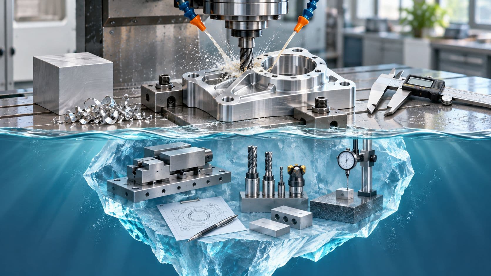
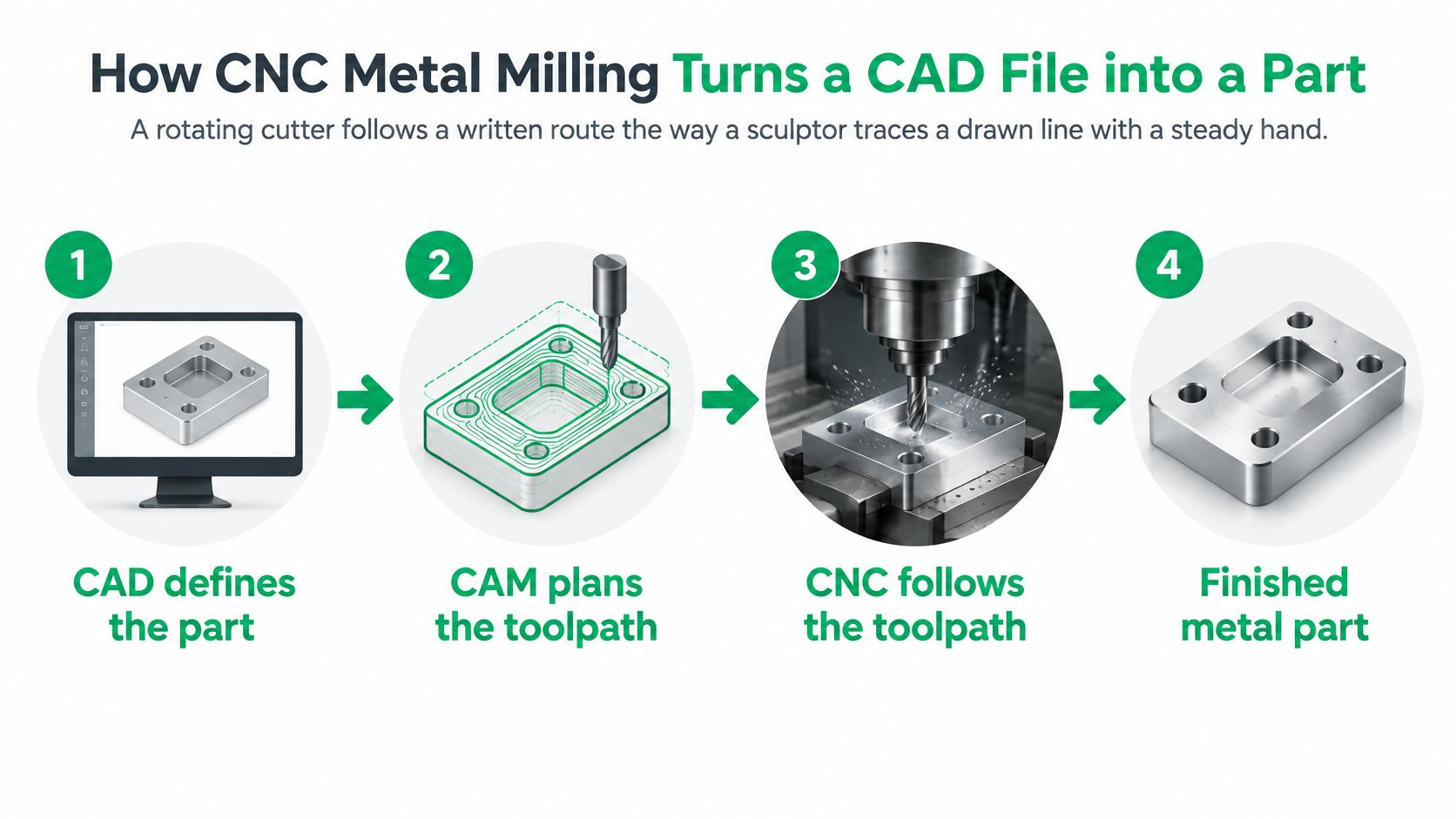
A rotating cutter follows a written route the way a sculptor traces a drawn line with a steady hand. The difference is that the hand never tires, and the route is numbers. CNC means computer numerical control. Your CAD model defines the shape, CAM software turns that shape into toolpaths, and the machine controller reads those toolpaths as coordinate instructions.
Say you're making a small aluminum sensor bracket with a pocket, four holes, and one flat mounting face. That simple part still passes through the same six stages as a complex housing. The global scale behind those stages is large, since the Mordor Intelligence milling machines market report valued the global milling-machines market at USD 14.81 billion in 2025.
The Machine Parts You'll Hear Named
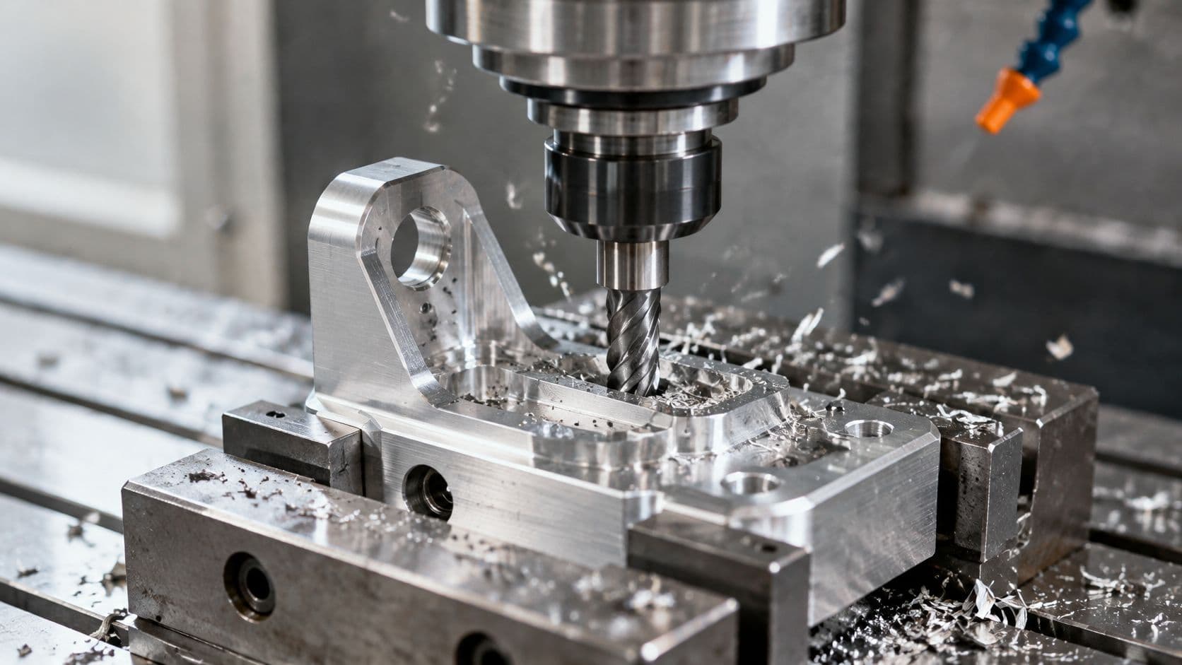
The spindle holds and spins the cutter. Depending on the material and tool size, it may run from a few thousand to over 20,000 rpm, with small tools in aluminum at the high end and larger tools in steel much lower. The worktable, vise, or fixture holds the raw stock so cutting forces can't move it.
Movement happens along linear axes. X usually moves left and right, Y moves front to back, and Z moves up and down. The controller coordinates those moves so the cutter can trace a straight wall, a circular bore, or a sloping surface without the operator turning handwheels.
Don't picture the machine reading your CAD file directly. It reads positions, feed rates, spindle speeds, and tool changes that CAM generated from your model.
Six Stages From Model to Inspected Part
- Model the part in CAD: You define the finished geometry, wall thicknesses, holes, and radii. The model says what the part should be, not how it'll be cut.
- Generate toolpaths in CAM: A programmer chooses cutters, roughing and finishing passes, stepovers, and entry moves. Good CAM work avoids air cutting, tool collisions, and unnecessarily small tools.
- Set up the fixture and work zero: The operator clamps the stock and tells the machine where X0, Y0, Z0 sits on that piece. Every coordinate in the program is measured from that point.
- Load tools and verify the program: Tools go into holders, lengths are measured, and the program is checked in simulation or with a cautious first run above the part.
- Run the cut: Coolant controls heat and clears chips while the operator watches tool load, chip color, and sound. A sudden change often signals a dull tool or a chip packing into a pocket.
- Inspect against the drawing: Calipers may be enough for a clearance slot, while a bore or true position callout may need a bore gauge or CMM. Inspection confirms the process, not just the single part.
Most rework starts before metal is cut. An unverified program can drive a tool into a vise, and a wrong work zero can shift every feature by the same error. If you check one thing before a first article, check those two. A perfect toolpath built from the wrong origin still makes a perfectly wrong part.
Choosing 3-Axis, 4-Axis, 5-Axis or Turning
More axes don't automatically mean a better part. They mean the cutter or workpiece can reach more orientations without someone unclamping, flipping, and re-indicating the part. Judge each option by geometry, setup count, and batch size.
| Machine type | Axes | Best for | Main limit | Relative hourly cost |
|---|---|---|---|---|
| 3-axis milling | 3 | Flat faces, pockets, slots, simple brackets | Features on other faces need re-setups | Lowest |
| 4-axis milling | 4 | Features on several faces, indexed rotary parts | Undercuts on one side still need re-clamping | Moderate |
| 5-axis simultaneous milling | 5 | Contoured surfaces, undercuts, complex parts in one setup | Higher rate and longer programming time | Highest |
| CNC turning | 2 (lathe axes) | Round or cylindrical parts such as shafts and bushings | Prismatic features need live tooling | Low to moderate |
What Each Row Means in Practice
A 3-axis mill cuts from one direction at a time, usually from the top. It's ideal when nearly all features sit on one or two parallel faces. A flat cover plate with pockets and through holes is straightforward. A cube shaped manifold with ports on five sides isn't, because each new face means another setup.
Every setup costs more than clamp time. The operator has to clean the fixture, locate the part, reset the work zero, and prove the first feature. Each flip also creates a chance for features on opposite faces to misalign by a small amount. That risk matters when a bore on the front must line up with a counterbore on the back.
A 4-axis mill adds a rotary axis, often a table that indexes the part around X or Y. The machine can present several faces to the spindle in one clamping, which suits valve bodies, indexed housings, and parts with holes around a central axis. It doesn't tilt freely into every undercut, so some geometry still forces a second clamping.
A 5-axis machine adds a second rotary movement. In simultaneous work, all axes can move together while the cutter stays at a controlled angle to a curved surface. That's valuable for impeller like forms, sculpted housings, deep cavities with drafted walls, and undercuts that a vertical cutter can't reach. You pay for it through a higher hourly rate, more CAM time, and more collision checking.
Turning flips the logic. The workpiece spins in a chuck and a mostly stationary tool removes material, which is efficient for shafts, bushings, rings, and threaded round parts. With live tooling, powered tools in the turret can mill flats, cross holes, and hexes without moving the part to a mill. Without live tooling, prismatic features mean a second operation.
The Setup Count Test
Use this test before you request the cheapest hourly rate:
- Count the 3-axis setups: List every orientation needed to reach all features.
- Multiply by realistic setup time: Include locating and first feature checks, not just clamping.
- Compare totals, not rates: Add setup time to cutting time for the whole batch, then compare with fewer setups at a higher rate.
For example, say a bracket has features on five faces and each setup takes 30 minutes. That's 150 minutes before you count repeat handling for every part in a batch. On a short run, one 5-axis setup can win even at the highest hourly cost because you remove four opportunities for delay and misalignment.
Practical rule: For prototypes, fewer setups often beat a lower hourly rate. For a simple plate that needs one setup anyway, 5-axis capability adds cost without adding value.
Batch size changes the answer as volume grows. If you'll make hundreds of the same bracket, a shop can justify a dedicated fixture that makes 3-axis flips fast and repeatable. For three prototypes, that fixture may cost more time than it saves.
Picking Aluminum, Steel or Engineering Plastic
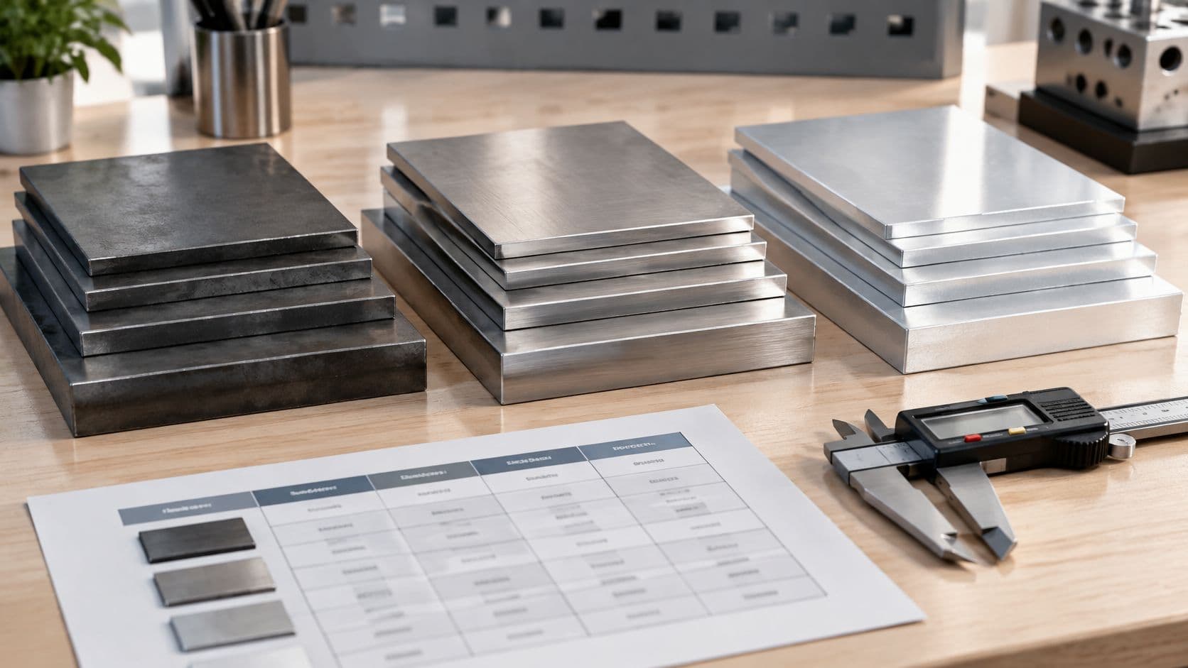
Start with function, then apply machinability as the first practical filter. Machinability describes how easily a material cuts, how quickly it wears tools, how it forms chips, and how reliably it holds size and finish. A material that looks perfect in a stress calculation can still be a poor prototype choice if it triples cycle time for no functional gain.
| Material and grade | Machinability | Typical uses | Watch for |
|---|---|---|---|
| 7075-T6 aluminum | Fair | Aerospace structures, high-load parts | Harder to cut, higher cost |
| 4140 and hardened tool steel | Poor when hardened | Wear parts | Tool life drops sharply |
| Titanium Ti-6Al-4V | Poor to moderate | Aerospace parts, implants | Heat in the cut limits speed |
| Acetal POM (Delrin type) | Very good | Gears, bushings, insulators | Expands with heat, holds tolerance less tightly |
| PEEK | Good with sharp tools | High-temperature and chemical-resistant parts | High material cost |
Aluminum Is the Usual Prototype Default
6061-T6 aluminum cuts quickly, produces manageable chips, and leaves a clean finish with standard carbide tools. It's a sensible default for brackets, enclosures, mounting plates, and housings where moderate strength and low weight are enough. If you're comparing grades and finishes for a first build, this guide to CNC machining aluminum will help you separate prototype convenience from production requirements.
7075-T6 gives you higher strength for aerospace structures and highly loaded parts. It still machines far more easily than steel, but it's harder than 6061, costs more, and isn't the grade to choose just because it sounds stronger. If your prototype only checks fit, 6061 usually answers the question sooner and cheaper.
Steels Trade Cutting Speed for Strength and Wear Resistance
Stainless steel 304 and 316 resist corrosion, so they're common in medical and food equipment. They also work-harden if a tool rubs instead of cuts, and they can produce gummy, stringy chips. Sharp tools, steady feed, and enough coolant matter. Letting a drill dwell at the bottom of a hole is a reliable way to make the next pass harder.
Mild steel 1018 and 1045 machine predictably and suit fixtures, shafts, and general machine parts. Their weakness shows up after machining. Without plating, paint, black oxide, or another finish, they'll rust in normal shop or service conditions.
4140 and hardened tool steels belong in wear parts, dies, and high load components. In a pre-hardened or hardened state, tool life drops sharply and cutting parameters get conservative. Sometimes the right sequence is to machine soft, heat treat, then finish grind critical surfaces. That sequence costs more, but it protects both tools and accuracy.
Titanium Ti-6Al-4V serves aerospace parts and implants where strength, weight, and corrosion resistance justify the effort. Heat concentrates near the tool contact point instead of leaving with the chip, so speed stays limited and tool condition needs close attention. Don't specify titanium for a fit check unless stiffness, weight, or biocompatibility is part of what you're testing.
Plastics Cut Easily but Move Differently
Acetal POM machines very well and works for gears, bushings, and insulators. It doesn't behave like a soft metal, though. It expands with heat, can flex away from the cutter, and holds tight tolerances less reliably over temperature changes.
PEEK handles high temperature and chemical exposure and cuts well with sharp tools. Its high material cost changes design decisions. You'll want stock size, nesting, and scrap considered before you approve a large blocky part.
Choose the material for the function first. Then ask whether the machinist can hold your tolerance and finish in that material at your quantity.
That order prevents two common mistakes. You won't pick an easy cutting plastic for a hot, loaded joint, and you won't demand a metal like tolerance on a plastic part that will grow or creep in service.
Tolerances and Surface Finishes to Specify
A drawing without tolerances doesn't mean every dimension must be exact. It usually falls back to a general standard, and ISO 2768 is the common fallback for linear dimensions. You still need explicit callouts where fit, sealing, alignment, or movement depends on size.
| Nominal size (mm) | Fine (f) | Medium (m) | Coarse (c) |
|---|---|---|---|
| 3 to 6 | ±0.05 mm | ±0.10 mm | ±0.30 mm |
| 6 to 30 | ±0.10 mm | ±0.20 mm | ±0.50 mm |
| 30 to 120 | ±0.15 mm | ±0.30 mm | ±0.80 mm |
Pick the Class by Function, Not Habit
Fine suits sliding fits, bearing seats, locating holes, and mating features where a small error changes assembly or movement. Medium suits most mechanical parts, including brackets, covers, and general hole patterns. Coarse suits clearance features, rough outlines, and dimensions with generous space around them.
Don't apply fine tolerance to the whole drawing because one bore is critical. Call out the bore, its position, and any datum relationship directly. Leave noncritical edges at medium or coarse so the machinist doesn't spend finishing and inspection time where it buys nothing.
Consider a worked example. Say a 20 mm locating hole in a 6061 plate receives a pin at a sliding fit. In the 6 to 30 mm band, the fine class gives ±0.10 mm, which is a reasonable starting point before you check the actual pin fit. A cosmetic cover face on the same plate can accept medium at ±0.20 mm as milled. Same part, different requirements.
Surface Finish Follows Contact and Sealing
Surface roughness is usually specified as Ra, the average roughness. As-milled surfaces typically sit around Ra 3.2 to 6.3 µm. A controlled finish pass can reach around Ra 0.8 to 1.6 µm. Very fine finishes below Ra 0.4 µm generally need polishing, lapping, or grinding rather than ordinary milling.
Use this surface roughness chart when you need to compare Ra values with the look and feel of common machined finishes. Then assign finishes face by face:
- Sealing faces: Specify a finer finish and flatness if a gasket or O-ring must seal.
- Bearing or sliding faces: Specify finish and tolerance together, since roughness affects friction and wear.
- Cosmetic outer faces: Accept as-milled or bead blasted finish unless appearance is a product requirement.
- Hidden clearance faces: Don't pay for a finish pass nobody sees and nothing contacts.
For that 20 mm pin hole, Ra 1.6 µm is a practical companion to the fine tolerance because the pin must slide without excessive play or wear. The outside cover face doesn't need the same treatment.
A tighter tolerance raises the cost of the whole part mainly when it forces extra passes, slower finishing, special tooling, or more inspection.
One tight bore in an otherwise simple plate may add little if it can be interpolated or reamed in the same setup. Ten tight features on different faces are different. They can drive setup strategy, inspection time, and scrap risk all at once.
Design Rules That Lower Machining Cost
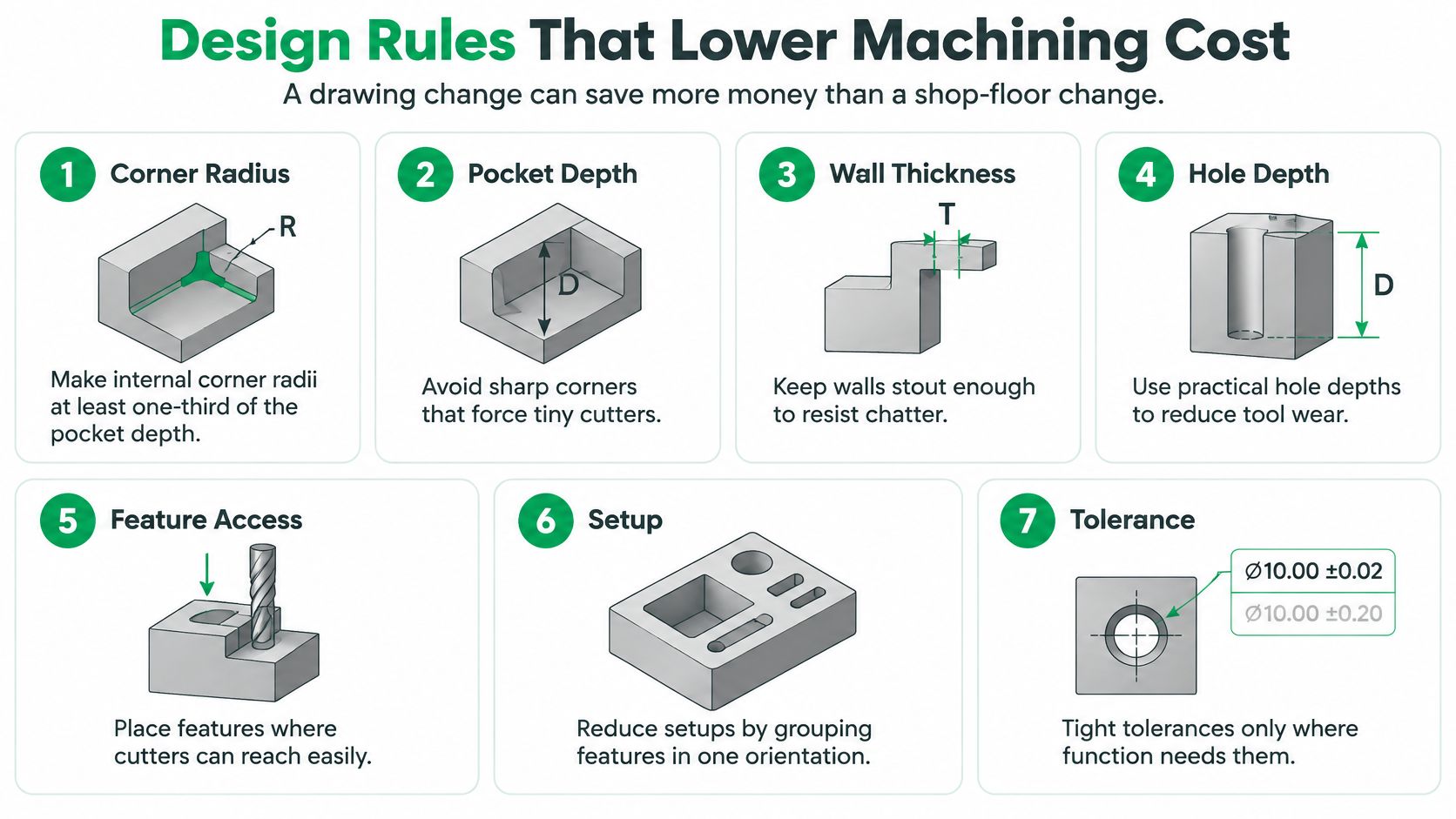
A drawing change can save more money than a shop floor change. By the time a machinist is choosing feeds and speeds, your radii, depths, walls, and feature layout have already decided which tools fit and how many setups are necessary. Use these rules while the model is still easy to change, and review the cost drivers in this guide to CNC milling cost before you freeze the design.
Seven Rules to Apply Before You Quote
- Make internal corner radii at least one-third of the pocket depth. A round end mill can't cut a perfectly sharp internal corner, and a tiny radius forces a small tool that must run slowly and take light passes.
- Keep internal pockets no deeper than four times their width. Deep, narrow pockets trap chips, deflect long tools, and often need multiple roughing strategies to reach the floor cleanly.
- Use standard drill sizes and keep blind holes within four to six times their diameter. Standard tools are already in the carousel, while very deep blind holes raise pecking time, drill wander, and breakage risk.
- Keep walls at least 0.8 mm thick in aluminum and 1 mm in steel. Thinner walls can chatter, deflect away from the cutter, or distort after unclamping, turning a simple pocket into scrap.
- Group features on the same face. Holes, pockets, and bosses that share one orientation can often be finished in one setup, which cuts handling and alignment error.
- Avoid undercuts unless function justifies them. An undercut may require a special cutter, a 4-axis index, or a 5-axis machine, so it should solve a real assembly or performance problem.
- Name one datum face and reference features to it. A clear datum tells the machinist how to locate the part and lets inspection check positions quickly from the same reference.
Each rule attacks a specific cost. Larger radii permit larger, stiffer tools. Shallower pockets reduce tool deflection. Sensible walls prevent vibration. Shared orientations remove setups. Clear datums remove arguments about whether a part passed.
First change to make: Group features on one face wherever the design allows it. It usually saves the most setups, and setups consume skilled time even when cutting takes only minutes.
Don't treat the numbers as absolute physical limits. A wall thinner than the guideline can sometimes be machined with support, light passes, or a different sequence. The point is that you'll pay in cycle time, risk, or inspection. Spend that money only when weight, space, or performance requires it.
Real Applications and the Prototype-to-Production Path
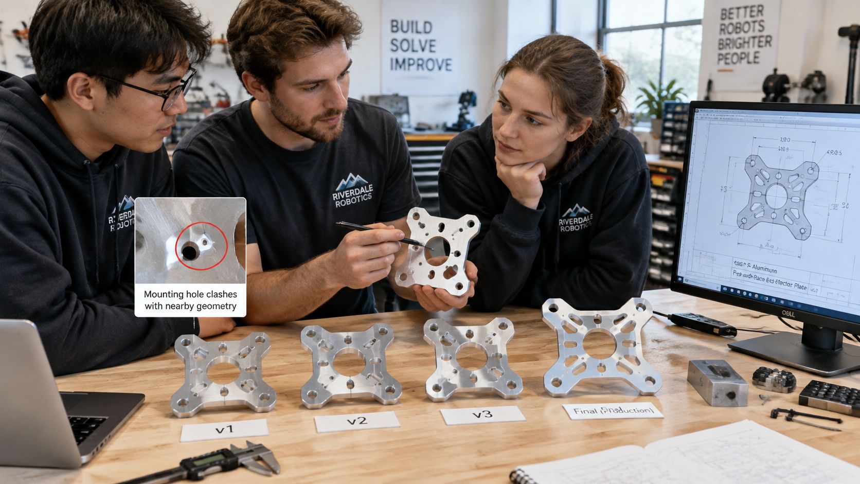
Say a robotics team needs a 6061 aluminum end-effector plate for a pick-and-place arm. They order three prototypes, bolt one to the arm, and discover a mounting hole clashes with a sensor bracket that wasn't in the simplified assembly model. That's a successful prototype. It found an interface problem while the fix was still a CAD edit and another short machining run.
Where the Process Fits
Applications differ, but the pairing of material and machine follows the geometry:
- Aerospace brackets: Often 7075 aluminum on 5-axis machines when pockets, angled faces, and weight reduction features would otherwise need several setups.
- Medical instrument housings: Commonly 316 stainless on 3-axis or 4-axis machines, where corrosion resistance and clean external surfaces matter.
- Automotive bench fixtures: Usually aluminum or steel on 3-axis machines, because plates, locating blocks, and clamps rely on flat datums more than sculpted surfaces.
- Gears and bushings: Often acetal on a 3-axis mill or lathe, depending on whether the part is mainly prismatic or round.
None of these pairings is a law. A simple aerospace spacer may belong on a lathe, and a medical prototype may start in aluminum to prove ergonomics before anyone cuts stainless.
Five Stages From First Part to Stable Supply
- One to five prototypes: You're testing fit, access, assembly order, and basic function. Fewer setups matter more than the lowest hourly rate because speed of learning is the goal.
- Design revision with DFM feedback: The machinist flags sharp corners, deep pockets, unreachable features, and tolerances that force extra work. You revise once, with evidence from real parts.
- Bridge batch of about ten to fifty parts: You test assembly variation, packaging, and early supply. Reused fixtures and a proven program start paying back here.
- Pilot run: The team confirms process stability, inspection capability, finish consistency, and documentation before committing to larger orders.
- Production or process switch: Milling may remain right for low volume metal parts. Once volumes reach several hundred, molding, casting, or a near-net-shape blank plus finish milling may beat milling every part from solid stock.
That last decision protects you from a common trap. CNC metal milling is excellent for learning and low volume production, but its per-part cost doesn't fall like a molded part's cost after tooling is paid for. Revisit the process when quantity, not geometry, becomes the dominant constraint.
Confirm Your Part Is Ready for a CNC Quote
A complete request gets a more accurate quote and avoids the back-and-forth that delays a project. Don't send only a screenshot and ask for a price. Give the machinist enough information to choose a machine, estimate setups, select tools, and plan inspection.
Your Pre-Quote Checklist
- Material and grade: Write 6061-T6, 316 stainless, Ti-6Al-4V, acetal, or the exact material you need. Aluminum alone isn't specific enough.
- Critical tolerances: Identify the features they apply to and the datums used to measure them. Mark noncritical dimensions as governed by your general tolerance class.
- Surface finish by face: State which faces seal, slide, show, or can remain as milled. Include coating or anodizing if it affects final dimensions.
- Quantity and timing: Separate the prototype quantity from the bridge or pilot quantity. Pricing changes because setup time is spread across more parts.
- Files: Send a STEP file for the 3D geometry plus a PDF drawing with datums, threads, tolerances, finishes, and revision level marked.
At FIRMFG, we review uploaded CAD files, return design-for-manufacturing feedback on the features that drive cost, and provide a free CNC machining quote within 24 hours after uploading CAD files. We have over 100 advanced CNC machines in-house, including 3-axis, 4-axis, and 5-axis machining centers, so we can match the part to the right machine without changing supplier.
Complete the checklist, upload the STEP and PDF, and request DFM feedback before you order the prototype. That one step catches unreachable features and overspecified tolerances while they're still inexpensive to fix.
Upload your STEP file and drawing to FIRMFG for a free CNC machining quote within 24 hours, with DFM feedback on setups, radii, tolerances, and material choice before cutting begins. Whether your part belongs on a 3-axis mill, a 5-axis machining center, or a lathe, you'll get a clear route from prototype to pilot run without guessing which machine fits.