EDM Machining Service Guide: Wire, Sinker and Tolerances
You just got the quote back on a hardened mold insert, and it sits well above the CNC number you had in mind. The cavity is deep, the internal corners are sharp, and the steel is already at full hardness. A mill cannot hold that corner without a radius the design will not accept, and a laser will not open a blind rib in a thick block.
That is the moment an EDM machining service stops being a specialty line and becomes the process that can make the part. The drawing still has to say what must survive loading, not only what a CMM should read.
Table of Contents
Wire EDM and Sinker EDM Side by Side- Three rules that pick the machine
Materials, Tolerances and Surface Finish Limits- What actually sets the number on the drawing
Lead Time and Cost Drivers for EDM Parts- What moves the quote
Design Rules and Drawing Checklist for EDM Parts- Copy this onto the drawing
Confirm Your Drawing Before You Request an EDM Quote
What an EDM Machining Service Does
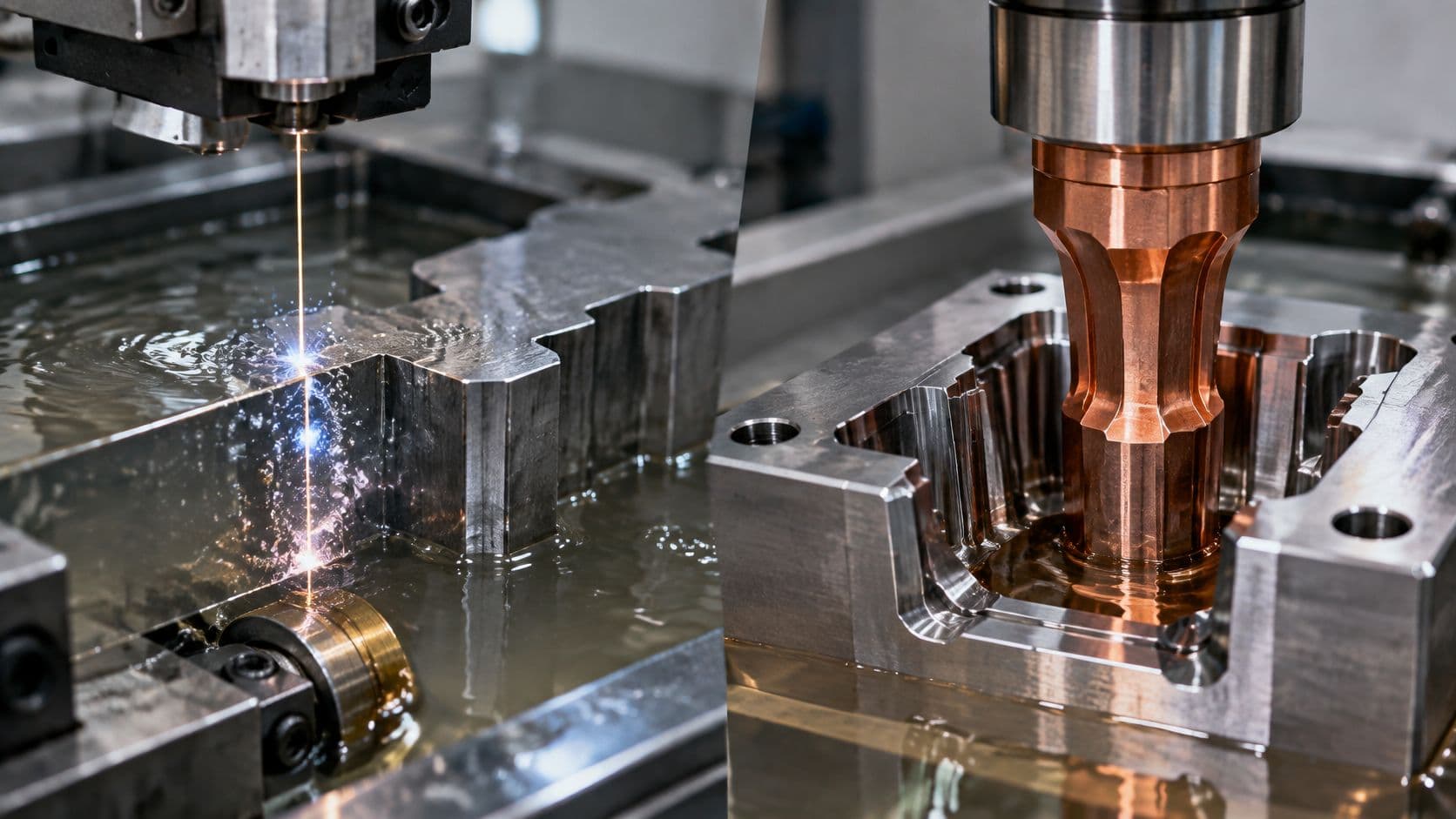
An EDM machining service removes conductive metal with repeated controlled sparks across a small dielectric-filled gap, so there is no cutting force on the part. Picture a controlled storm of tiny lightning strikes. Each spark is a microscopic erosion event, not a continuous cut. Experimental literature puts the volume removed by one discharge at about 10^-6 to 10^-4 cubic millimeters, depending on energy, material, pulse duration, and process conditions, as a SpringerOpen EDM review reports. Accuracy comes from millions of those sparks, not from one pass of a tool.
The same review notes that the cumulative effect machines conductive metals regardless of hardness, as long as the part completes the circuit and the dielectric supports stable sparking. Hardened tool steel, tungsten carbide, titanium, and nickel superalloys can be finished after heat treatment. Narrow slots, deep cavities, sharp internal corners, and high depth-to-width features become practical when a rotating cutter would deflect or not fit. Automotive and aerospace parts, including hard nickel-alloy turbine features, sit alongside mold and die work, medical components, and low-volume prototypes.
Two service types cover nearly every job. Wire EDM cuts a through-profile with a continuously fed wire. Sinker EDM burns a cavity from a shaped copper or graphite electrode. The wire path itself is easier to picture once you see how wire EDM works.
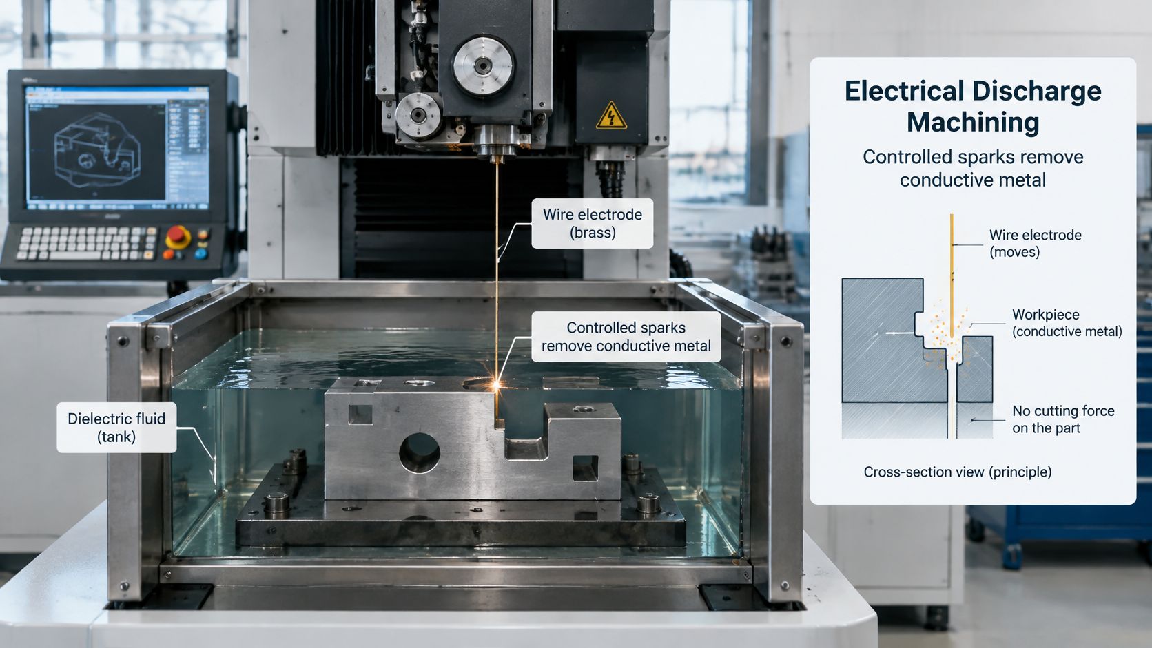
Removal is slower than conventional cutting. That slower rate is the price of non-contact control and geometric flexibility. What follows is which process fits, what finish to expect, what drives cost and lead time, how to design the part, and when CNC or laser is the better call.
Choosing the Right Process
Match the process to the constraint that blocks the part. Hardness, corner sharpness, slot depth, sheet thickness, and how much stock you still have to remove decide the winner faster than a general preference for one machine.
| Criterion | EDM | CNC Milling | Laser Cutting |
|---|---|---|---|
| Sharp internal corners | Good with wire EDM | Limited by tool radius | Limited |
| Bulk material removal speed | Slow | Fast | Fast on thin sheet only |
| Thin sheet profiles | Works but slow | Poor | Excellent |
| Deep narrow slots | Excellent | Limited by tool length and deflection | Not suitable |
| Cost on simple, open geometry | Higher | Lower | Lower |
| Heat-affected edges | Recast layer present | Minimal | Heat-affected edge present |
When each process wins
Choose EDM when the part is hardened past what cutters can machine economically, when you need sharp internal corners or deep narrow slots, or when the feature is a tool, punch, or mold detail. There is no tool pressure, so thin ribs and already-hard inserts stay straight.
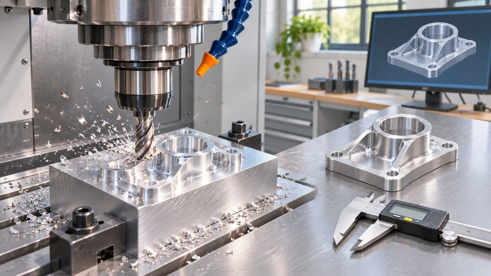
Choose CNC milling when the alloy is soft or only moderately hard, the geometry is open, and speed or quantity matters more than a knife-edge corner. Open pockets, bosses, and datum faces belong on a mill. For metal prototypes and short runs, CNC machining for metal parts is usually the faster bulk path, and FIRMFG offers CNC machining with 3-, 4-, and 5-axis capabilities for prototyping and low-volume production.
Choose laser cutting for thin sheet profiles where a heat-affected edge is acceptable. It is the wrong tool for deep slots, blind cavities, and thick hardened blocks.
Practical rule: Rough the open stock on a mill, then burn only the feature a cutter cannot hold.
A split route is often the cheapest honest plan. CNC-machine the mold base while the steel is still easy to cut. Heat-treat the insert. Wire-cut the through profile, and sink only the blind rib. Burning the whole block from a raw billet wastes machine hours on stock a mill would have cleared in minutes. Simple, open geometry priced on EDM will lose to milling or laser every time.
Wire EDM and Sinker EDM Side by Side
Scan the differences before you lock a process on the drawing. Electrode type decides the shapes you can buy, and it also decides most of the setup cost.
| Factor | Wire EDM | Sinker EDM |
|---|---|---|
| Electrode | Continuously fed brass or coated wire, consumed during cutting | Shaped copper or graphite electrode made for each cavity |
| Shapes produced | Through-profiles, punches, slots, outlines | Blind cavities, ribs, textured mold faces, internal shapes |
| Part height | Up to several hundred mm, depending on machine | Limited by electrode depth and flushing access |
| Corner radius | Set by wire radius plus the spark gap | Limited by electrode tip wear and fabrication |
| Typical tolerance | About ±0.002 to 0.01 mm on finish passes | Held by electrode accuracy, spark gap, and wear compensation on finish burns |
| Surface finish (Ra) | About 0.2 to 1.6 µm after finish passes | Set by finish-pass energy; confirm the face, do not copy the wire number |
| Cost tendency | Low setup for flat profiles; wire consumption adds to cost | Electrode fabrication adds cost; efficient for repeat cavities |
| Typical use | Injection mold inserts, stamping punches, aerospace profiles | Die cavities, mold details, turbine root slots, medical molds |
Three rules that pick the machine
A through feature is a wire job. Punches, fine slots, and outlines that must cut the full height of the workpiece belong on wire. The wire is consumed as it cuts, so the wire stays fresh. A stamping punch with straight walls is the clean example. You program a profile, not a negative of the part.
A blind feature needs sinker EDM. Closed cavities, ribs, textured mold faces, and internal shapes a wire cannot reach are burned from a shaped electrode. An injection-mold insert with a deep blind rib is the matching example. The electrode never becomes a 1:1 copy of the cavity. You offset it for the spark gap, then plan wear at the corners.
Many real parts use both. Wire-cut the outline, then sink the internal detail. Trying to wire a blind pocket fails because the wire has to start and exit through the stock. Trying to sink a simple through profile pays for an electrode you did not need.
A sinker electrode is machined, cleaned, and wear-compensated for each cavity. Shops commonly split that into a roughing electrode and one or more finish electrodes, because corners round off as the burn progresses. Where the table leaves sinker corner radius, tolerance, or Ra as a process outcome rather than a fixed band, treat those cells as quote items. Do not assume the wire numbers transfer to a deep cavity.
Materials, Tolerances and Surface Finish Limits
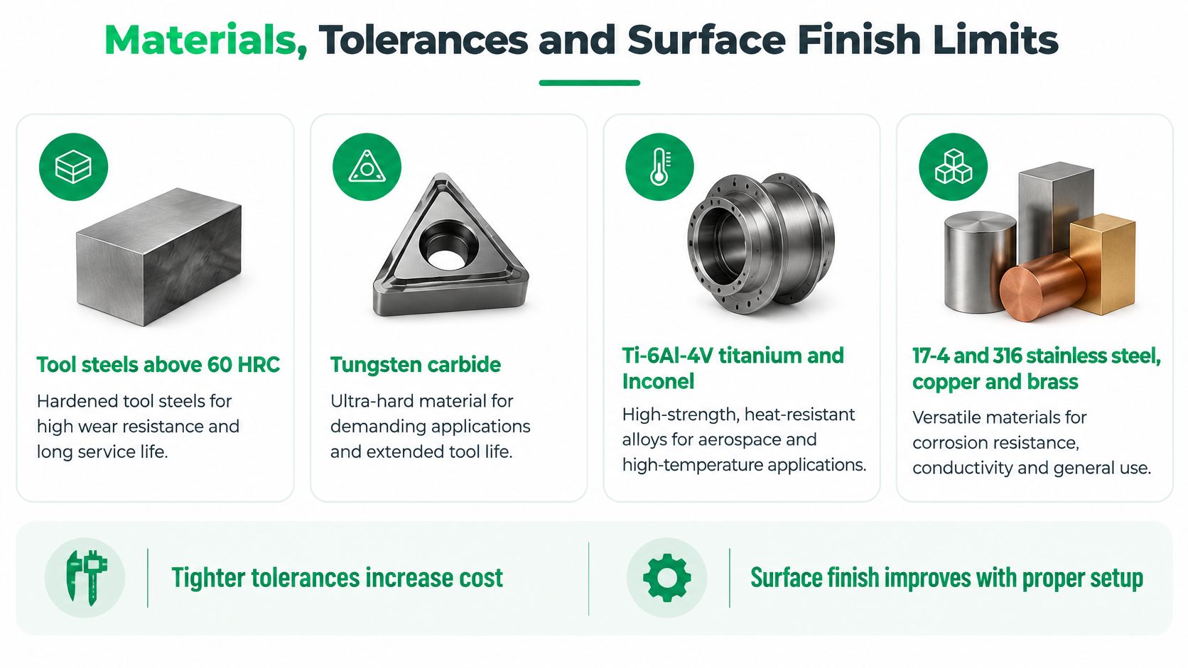
Conductivity comes first. If the workpiece cannot close the circuit, EDM cannot cut it. Hardness is almost irrelevant once that rule is met, which is why shops burn tool steel after it has passed 60 HRC instead of fighting it with carbide end mills.
| Material | EDM suitability | What to watch for |
|---|---|---|
| Tungsten carbide | Excellent | Slow removal rate; plan extra time for roughing |
| Ti-6Al-4V titanium | Good | Recast layer and heat-affected zone; control with finish passes |
| Inconel and nickel superalloys | Good | Slow but reliable; common for turbine features |
| Copper and brass | Possible | Often used for electrodes; soft, so control burrs and edge quality |
| Aluminum | Possible but slow | Debris and flushing can cause unstable sparking; not usually the first choice |
| Plastics and ceramics | Not possible | Non-conductive; use CNC, molding, or conductive-filled grades instead |
17-4 and 316 stainless sit with the other conductive alloys. They burn cleanly. Aluminum can be burned, but chips and flushing often make the gap unstable, so a mill is usually the first choice. Plastics and ceramics stay off the machine unless a conductive filler is specified and proven.
What actually sets the number on the drawing
Dimensional performance depends on electrical energy, electrode geometry, gap conditions, flushing pressure, polarity, and thermal surface integrity, not only on machine positioning. A SpringerOpen parameter review lists pulse-on time, peak current, voltage, duty factor, electrode gap, polarity, and flushing pressure as the variables that govern removal rate, electrode wear, roughness, and accuracy.
That review cites a copper-electrode study with surface roughness of approximately 2.157 µm at 5 A peak current, 6 µs pulse-on time, and 10 kg/cm² jet pressure. A higher-energy combination of 15 A and 20 kg/cm² produced approximately 4.853 µm under that study's conditions. Those figures are process-specific benchmarks, not a promise on your alloy.
A finer Ra is bought with lower energy and better flushing, and it has to be proven on the actual thickness, electrode, and dielectric.
EDM also leaves a resolidified recast layer and a heat-affected region. That layer matters on fatigue-critical, sealing, medical, and aerospace faces. Separate rough EDM, finish EDM, wire-cut profile accuracy, and any post-EDM surface requirement on the drawing. For how those wire targets are written, see wire EDM tolerances. Changing dielectric or flushing can move wear and roughness enough that a parameter set from a different alloy should not be copied onto yours.
Lead Time and Cost Drivers for EDM Parts
You control three levers before anyone sets a price. Relax tolerances that do not carry load. Call out finish only on faces that seal, slide, or see fatigue. Bundle features into one setup so the machine is not re-indicated for every pocket.
EDM is priced by machine time, electrode work, and inspection, not by the raw billet. An EDM process review in Manufacturing Review states the trade-off plainly. Material-removal rate is generally lower than conventional cutting, while electrode wear and recast-layer formation become important outputs. Peak current and pulse-on time dominate. Raising either generally raises removal rate, and it also increases crater size, roughness, electrode wear, and thermal damage.
What moves the quote
- Electrode count. Each sinker cavity needs a shaped electrode, and a deep detail often needs a rougher plus a finisher.
- Depth-to-width ratio. A narrow, deep burn slows down because debris has nowhere to go.
- Tolerance and Ra. Extra finish passes are extra hours. One parameter set cannot optimize speed and finish at the same time.
- Material. Carbide and nickel alloys cut reliably and slowly. Long wire profiles also consume wire.
- Inspection depth. A recast check or a full layout adds queue time on top of burn time.
- Flushing. Too little debris removal causes short circuits, dimensional drift, and local defects. Dielectric choice is a design variable, not a shop secret.
Lower current, shorter pulses, and longer pulse-off time usually produce a finer finish, because the longer off-time clears debris and reduces unstable arcing. For quoting, separate roughing and finishing, state the finish range, and ask for inspection of critical features only.
A hardened insert that needs one roughing pass and two finish passes costs more than the same insert with a relaxed Ra on non-functional faces. Roughing trades surface quality for speed. Finishing trades time for accuracy. A tight tolerance and a fine Ra each add cost, so do not put both on every face.
Lead time on a small batch is set by setup, electrode fabrication, and those extra passes. A complete drawing, with hardness after heat treatment and finish called out by face, avoids a quote revision that adds days. Incomplete notes send the job back for clarification before a machine is even reserved.
Design Rules and Drawing Checklist for EDM Parts
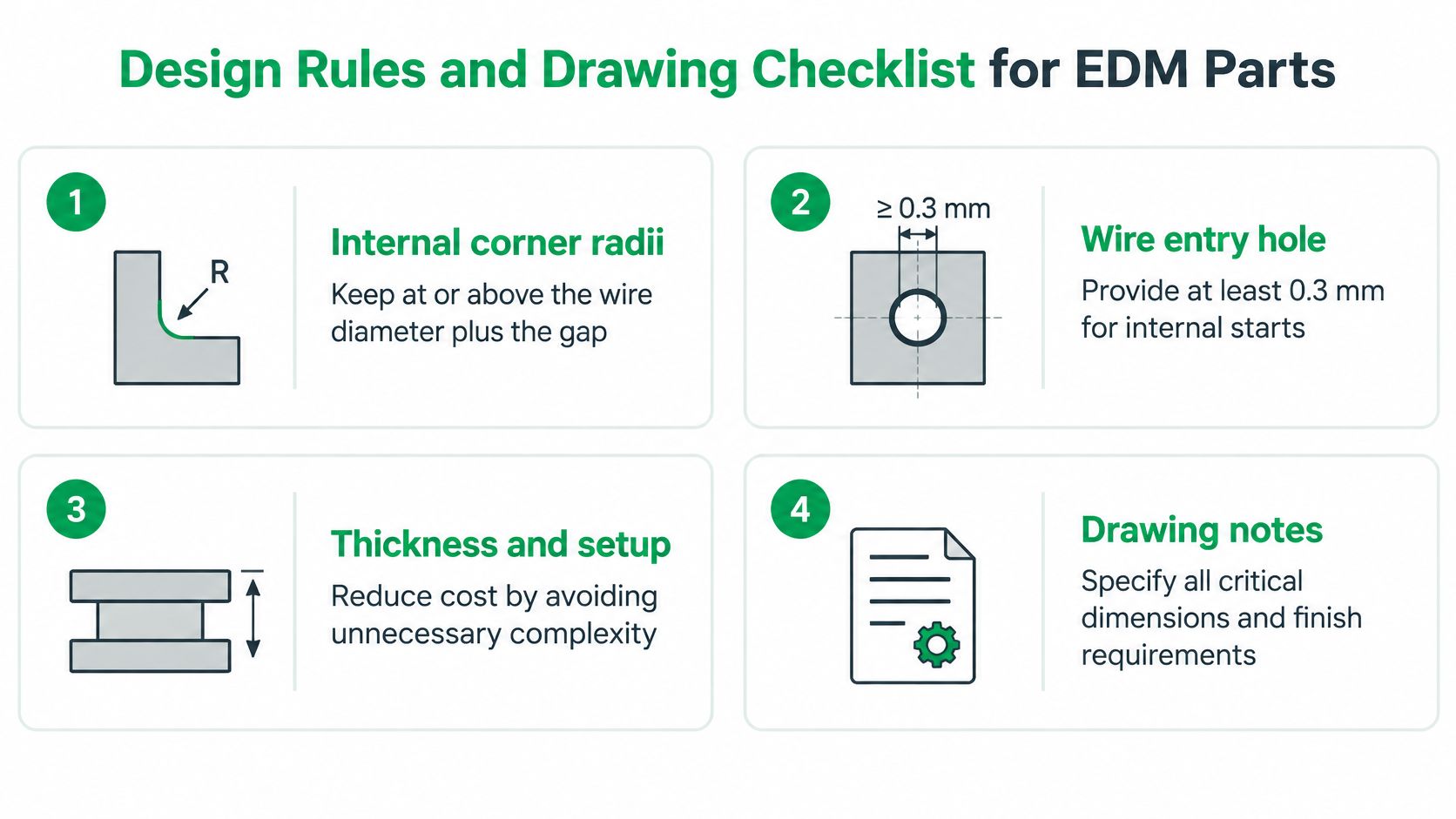
Design for the electrode and the flush path, then specify the surface that has to survive service. A cheap feature on CAD becomes an unstable burn if the gap cannot clear debris.
Internal corner radii should stay at or above the wire diameter plus the spark gap. Asking for a dead-sharp wire corner forces a smaller wire, a slower cut, or a sinker detail you did not budget.
Wire entry for an internal profile needs a start hole of at least 0.3 mm. Without it, the wire cannot begin inside a closed shape.
Blind cavities should stay within about four times their width where you can. Deeper pockets need electrodes and flushing that are hard to hold, and cycle time climbs fast.
Electrode clearance has to let the electrode enter and leave. Hidden undercuts usually mean a second electrode or a redesign.
Thin ribs are slow and less accurate. The flushing gap and electrode vibration both work against a fragile wall, even though there is no cutter load.
Copy this onto the drawing
A dimensionally accurate part can still be unfit for service if you only check nominal tolerance and Ra. EDM can leave a hard, brittle recast layer with craters, resolidified globules, micro-porosity, and microcracks. A Wiley review of EDM surface condition identifies micro-porosities below 50 micrometers as potential crack-propagation paths. On Ti-6Al-4V, that same work reports that a coated wire and a multi-pass strategy produced up to 40% less recast-layer thickness, an 8% lower Ra, and a 31% increase in cutting speed.
Specify surface integrity on load-carrying, sealing, and patient-contact faces. Leave the rest at a standard EDM finish.
- Name the critical surfaces. Mark fatigue, seal, wear, and cleanliness faces separately from cosmetic ones.
- State the skim-pass requirement. Rough wire cuts and finish passes are not the same surface. Say which faces get a low-energy skim.
- Set an acceptable recast depth. Higher pulse energy thickens the layer and roughens the face. Write the depth you will accept, or state that the layer must be removed.
- Define edge condition. Burrs, wire-entry marks, and rounded corners belong in the note, not in a verbal aside.
- Name the inspection method. Cross-section metallography or a microscope check for high-integrity parts. A CMM report does not see a crack path under the skin.
If the face carries load, seals, or touches a patient, tolerance and Ra are not the specification. Recast depth and the inspection method are.
Confirm Your Drawing Before You Request an EDM Quote
Work the drawing in this order so the quote prices the part you will accept.
- Mark every feature as through, blind, or internal. That single mark picks wire, sinker, or both.
- List the alloy and the hardness after heat treatment. Final hardness decides whether EDM runs before or after the furnace.
- Put tolerance and Ra on each critical surface, using the checklist above. Do not blanket the whole part.
- State recast-layer depth and the inspection method on the faces that see fatigue, sealing, or patient contact.
- State quantity and intent. A one-off prototype and a repeat cavity do not share the same electrode plan.
- Ask for DFM feedback before you freeze the drawing. FIRMFG offers wire EDM service and provides free DFM feedback, with engineers reviewing designs and suggesting changes that suit CNC machining, including which features should stay on a mill.
Compare shops on process, inspection evidence, and lead time, not on price alone. A low quote with no finish callout and no recast note often becomes rework after the first article fails a fatigue or seal check.
The decision to make now is simple. Send the drawing with critical surfaces marked, and ask for a process recommendation before you choose between wire and sinker.
FIRMFG machines conductive parts with wire EDM alongside 3-, 4-, and 5-axis CNC, so hardened details and open geometry can stay on one route from prototype through a short run. If your insert needs a through profile, a tight corner, or a finish that has to survive loading, send the drawing with critical surfaces and recast notes marked. Visit FIRMFG and ask for a process recommendation before you lock wire or sinker on the quote.