How to Produce a Prototype from CAD to First Part
You have a finished CAD model, a target date, and no clear answer to the question that matters most: what is the fastest, least wasteful way to get a part that proves the design? The drawing may look complete, but the next decisions determine whether the first build teaches you something useful or consumes time producing an expensive mistake.
Learning how to produce a prototype is less about moving from sketch to CAD and more about controlling the decisions after CAD. Define the validation goal, choose a process that matches it, apply tolerances selectively, invite useful DFM feedback, and document what the part demonstrated. That workflow prevents five common failures: vague objectives, unsuitable processes, over-specified drawings, skipped manufacturing review, and the assumption that one successful prototype is ready for production.
Table of Contents
Define What Your Prototype Must Prove- Give each build one primary job
Choosing the Right Prototyping Method for Your Part- CNC machining
Materials Tolerances and the Cost of Over-Specifying- Apply precision where failure would occur
Working Through DFM Feedback and Quotes- Read the quote as a process plan
Finishing Inspection and Deciding Whether the Part Passes- Inspect the characteristics that matter
Moving From Prototype to NPI Without Losing What You Learned- Convert prototype evidence into production controls
Why Most Prototype Builds Go Wrong Before They Start
An engineer can spend weeks refining geometry, then lose the schedule through a rushed RFQ, a production-style tolerance scheme, or a process chosen because it looks familiar. The first physical part isn't determined by CAD alone. Material, tooling access, inspection requirements, finishing, supplier capability, and revision speed all shape the result.
The most expensive mistake is treating the prototype as a small production run. A prototype should answer a defined question. It may need to confirm that two parts fit, that a mechanism moves, that a housing feels right in a user's hand, or that a proposed geometry can be manufactured. Those are different tests, and they shouldn't share the same process plan.
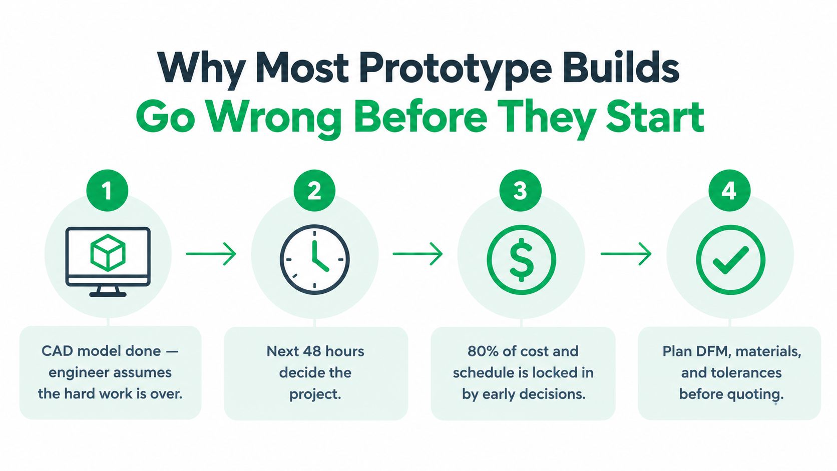
The decisions that control the first build
Start by writing a one-sentence validation statement. “Confirm the motor mount holds position under operating load” is useful. “Build the prototype” isn't. The first statement identifies function, interfaces, material expectations, and likely inspection points.
Then make five decisions before requesting a quote:
- Validation goal: Decide whether you're testing fit, form, function, manufacturability, or assembly sequence.
- Process: Select CNC machining, additive manufacturing, molding, casting, or sheet metal according to the question, not habit.
- Material: Choose a material that represents the property under test. A cosmetic resin won't validate a load-bearing metal interface.
- Tolerance strategy: Tighten only dimensions that affect the test. Every unnecessary callout can add inspection and process burden.
- Iteration path: Assume the first part may expose a design or process issue. Leave room for revision rather than spending the entire schedule on one build.
Practical rule: A prototype earns its cost by reducing uncertainty. If you can't state which uncertainty the part will remove, the design isn't ready to release.
The workflow continues after delivery. Inspect the critical features, record what passed and failed, capture supplier feedback, and convert those findings into requirements for the next build. That record is what allows a validated prototype to become a controlled NPI input instead of a disconnected sample.
Define What Your Prototype Must Prove
The most effective prototype is usually the smallest physical or digital artifact that answers the current engineering question. A full-featured part can look impressive while testing too many variables at once. If it fails, you may not know whether the problem came from geometry, material, tolerance, assembly order, or the manufacturing process.
Give each build one primary job
Separate the validation categories before selecting a method:
- Fit: Do mating parts, fasteners, seals, and interfaces align?
- Form: Are proportions, ergonomics, appearance, and user-facing surfaces acceptable?
- Function: Does the assembly carry load, move, seal, conduct, dissipate heat, or perform its intended task?
- Manufacturability: Can the chosen process create the geometry with suitable access, wall thickness, draft, and repeatability?
- Assembly sequence: Can operators install the parts in the intended order without interference or special handling?
A prototype can support secondary checks, but one primary goal keeps the build economical. A machined metal bracket may be appropriate for load testing, while a 3D-printed enclosure may be enough for connector placement. Combining those parts in one assembly can validate interfaces without forcing every component into its final process.
Simplify the first physical build
A foundational MIT prototyping study found that prototypes with fewer parts correlated with better design outcomes. Adding fewer parts during development was also associated with stronger results. The practical implication is straightforward: remove features that aren't needed for the current decision, reduce unnecessary interfaces, and avoid building a complete product when a subsystem can answer the question.
The same study reported average participant time allocations of 54% fabrication, 32% debugging, 22% design, and 9% class time. Those figures show why schedule planning must protect time for making and debugging. Fabrication is rarely a minor administrative step, and a prototype plan that allocates nearly all available time to CAD leaves no margin for setup issues, failed parts, or design changes.
Decide whether a physical part is necessary
Use simulation, a digital twin, or a simplified mockup when the question is primarily geometric, kinematic, or structural and the model can represent the relevant boundary conditions. A physical build becomes more important when users must handle the product, material behavior affects performance, interfaces depend on real surfaces, or compliance and safety require physical evidence.
Ask three questions:
- What decision must someone make after seeing or using the artifact?
- Can a virtual model answer that decision with credible inputs?
- What physical behavior would a digital model fail to reveal?
If the answer to the third question is weak, minimize the physical prototype. If it concerns friction, deformation, thermal behavior, sealing, tactile response, or real assembly variation, build the smallest representative part that exposes that risk.
Rapid iteration also changes the planning assumption. An empirical study of prototyping behavior recorded 203 prototypes created by four independent teams during a 4-day hackathon (study of prototyping behavior). Short cycles make more sense than betting the schedule on one elaborate first article. Plan the learning loop, not only the first delivery.
Choosing the Right Prototyping Method for Your Part
Process selection should follow the validation goal, geometry, material behavior, finish, quantity, and expected revision path. No single method is universally fast. CNC machining may be the fastest route to a credible metal part, while additive manufacturing may produce a complex plastic shape sooner. Rapid tooling becomes more sensible when several functional molded parts are needed and the production material matters.
| Method | Best For | Quantity Range | Lead Time Profile |
|---|---|---|---|
| CNC machining | Functional metal or plastic parts, tight interfaces, representative materials | One to small batches | Fast for accessible geometry, slower when setups, deep features, or difficult tooling access increase |
| 3D printing | Complex geometry, early fit checks, lightweight forms, rapid design changes | One to small batches | Often rapid, with finishing and post-processing added separately |
| Rapid injection molding | Functional molded parts and bridge builds using production-like resins | Small to moderate batches | Tool preparation adds upfront time, then repeat parts become efficient |
| Vacuum casting | Appearance models, elastomeric components, small replicated batches | Small batches | Quick after silicone mold preparation, with material and finish options influencing timing |
| Sheet metal fabrication | Brackets, enclosures, panels, folded structures | One to small batches | Efficient for developable sheet geometry, with bending, welding, and finishing affecting the schedule |
| CNC turning or milling with advanced axes | Rotational parts and complex multi-face components | One to small batches | Efficient when the geometry suits the machine, but programming and fixturing matter |
CNC machining
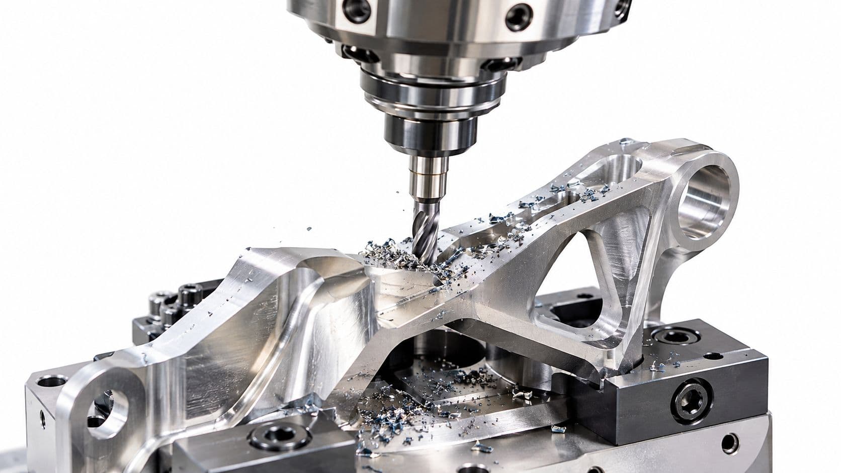
Choose CNC when the prototype must behave like a metal or engineering-plastic component. It offers strong material fidelity, accurate interfaces, and useful surface finishes, but the design must respect tool access, setup count, internal radii, and stock size. A complex five-axis part may avoid multiple fixtures, while a simple three-axis part can be cheaper when its faces are accessible.
For a practical process overview, review this guide to the CNC machining process. Don't ask machining to reproduce a molded feature set without modification. Deep pockets, sharp internal corners, thin walls, and hidden tool paths can turn a straightforward part into a costly one.
3D printing
SLA works well for detailed appearance models and smooth surfaces. SLS is useful for more complex polymer geometries without traditional support structures, while FDM can be practical for larger, lower-cost functional checks where layer direction and surface texture are acceptable. Metal additive manufacturing can address complex metal forms, but it still requires attention to support removal, post-machining, surface condition, and material certification.
Printing is a poor substitute for production validation when anisotropy, porosity, surface friction, or thermal performance matters. It may prove fit while concealing behavior that will change in injection molding or machining.
Molding, casting, and sheet metal
Use rapid tooling when the part must be tested in a production-like resin or when a bridge build needs repeated molded components. Vacuum casting suits appearance models and small replicated batches, especially when the design needs polyurethane options rather than a printed resin.
Sheet metal is usually the direct choice for enclosures, brackets, and folded frames. It can be combined with machined inserts, printed covers, or off-the-shelf hardware. Hybrid assemblies often outperform a forced single-process build because each method handles the feature it suits best.
Sacrifice cost, speed, or fidelity deliberately. Don't sacrifice all three accidentally.
Materials Tolerances and the Cost of Over-Specifying
Prototype drawings often fail because engineers copy the production tolerance scheme before they know which dimensions matter. That approach feels safe, but it can make every feature expensive to inspect and every difficult corner expensive to manufacture.
Independent DFM guidance warns that over-tolerancing can force full inspection on every part, inflate quotes by 20–40%, and extend lead time by 1–3 days (prototype DFM guidance). Sharp internal corners create a separate problem. They may require smaller tools or EDM, increasing cycle time by 30–60% and adding 3–5 days.
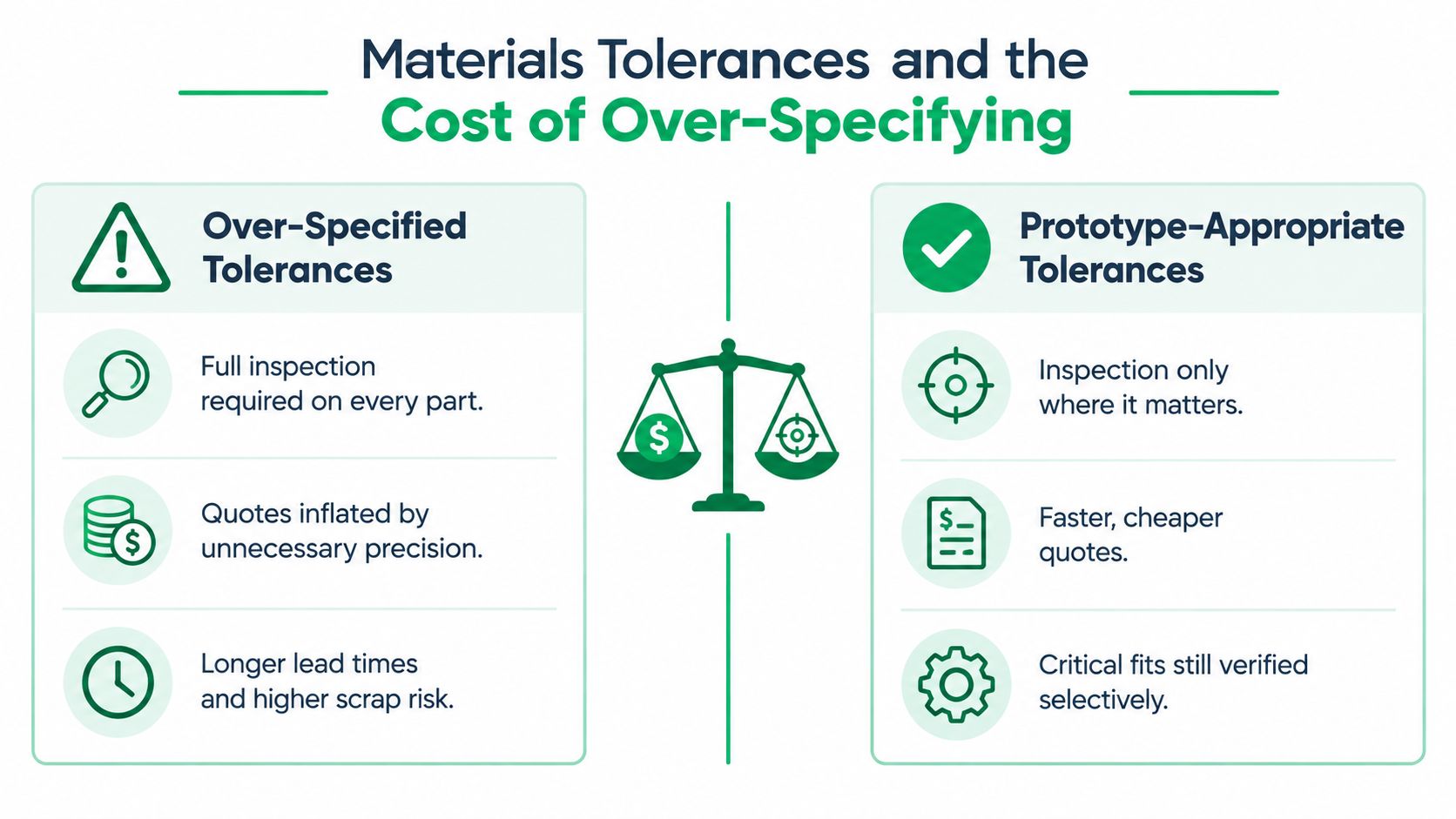
Apply precision where failure would occur
Mark critical dimensions explicitly. These may include bearing seats, locating bores, sealing surfaces, connector positions, datum relationships, or interfaces that control motion. Leave cosmetic and non-functional dimensions at the supplier's standard capability unless the appearance or assembly test requires otherwise.
A useful drawing separates three layers:
- Critical characteristics: Tight limits, defined datums, and inspection method.
- Important characteristics: Controlled dimensions that affect assembly or performance but don't need maximum precision.
- General geometry: Standard process tolerance, with supplier confirmation.
That hierarchy helps the manufacturer quote the actual risk instead of treating the whole part as precision work.
Match materials to the question
Aluminum is often useful for lightweight structural checks and quick machining. Steel may be necessary for wear, stiffness, heat, or load behavior. Engineering plastics can reveal sliding, electrical, chemical, or weight-related behavior, but the selected grade matters. Resins can demonstrate appearance and form while failing to represent production plastic strength or temperature performance.
Don't choose material by name alone. Record the property under test, the expected finish, and whether the prototype must survive repeated use. A surface treatment can also change dimensions, friction, corrosion resistance, and appearance, so specify whether it belongs on the test article or only on the final product.
Review the tolerance stack
Build a tolerance stack around the function, not around every dimension on the drawing. Identify the worst-case and likely assembly condition, then ask which contributors can be relaxed without changing the result. Model fixturing and setup references early, because a theoretically tight feature may be difficult to measure or reproduce from the proposed datum structure.
A successful prototype drawing isn't the one with the most decimal places. It's the one that tells the supplier where precision matters and gives the supplier freedom everywhere else.
Working Through DFM Feedback and Quotes
After an RFQ, the supplier's response should contain more than a price and delivery estimate. A useful quote exposes manufacturing assumptions before they become purchase-order surprises. It should identify difficult features, required setups, material availability, finishing constraints, inspection needs, and any mismatch between the drawing and the selected process.
Send a clean package:
- Released CAD: Include the correct revision and suppress irrelevant construction bodies.
- Drawings: Show datums, critical tolerances, materials, finishes, and inspection requirements.
- Quantity and timing: State the initial build size, desired delivery window, and whether revisions are likely.
- Validation goal: Explain what the part must prove so the supplier can recommend a suitable method.
- Assembly context: Provide mating parts or interface dimensions where fit depends on surrounding components.
Expect DFM comments about wall thickness, draft angles, tool access, sharp corners, tolerance callouts, and setup count. A supplier that flags these items early is giving you schedule information, not obstructing the design.
For a deeper explanation of the review process, use this guide to design for manufacturability. Respond to each comment by classifying it as must change, change if practical, or retain for a specific validation reason. That keeps design intent visible while preventing the team from accepting every suggestion without analysis.
Read the quote as a process plan
A fast quote is useful only if it includes enough assumptions to compare fairly. Check whether the price includes material certification, surface treatment, inspection reports, programming, tooling, fixtures, packaging, and shipping. Compare the proposed process against the validation goal, not only the unit price.
The cost, speed, and fidelity trade-off changes by stage:
- Early concept: Prioritize speed and low commitment. Simplified prints, mockups, or partial parts may be sufficient.
- Functional validation: Prioritize representative material and interfaces. Machining, molding, or a hybrid assembly may justify more effort.
- Pre-production: Prioritize repeatability, documented inspection, process capability, and supplier feedback that can transfer into NPI.
Schedule at least one decision point after the first DFM response. If the supplier recommends a geometry change, the engineer needs time to update CAD, revise drawings, and approve the new process. A quote that ignores revision time isn't a complete schedule.
Consolidating compatible processes with one supplier can also reduce handoff delays. It may allow machined, molded, cast, sheet-metal, and finished components to be coordinated against the same assembly requirements. FIRMFG, for example, provides CNC machining, additive manufacturing, sheet metal, molding, casting, finishing, and DFM support for prototype and low-volume workflows.
Finishing Inspection and Deciding Whether the Part Passes
A raw part isn't automatically the right test article. Finish selection should reflect what you're validating. Anodizing can support aluminum corrosion and appearance requirements, powder coating can represent a durable coated surface, electroplating can address conductivity or wear, bead blasting can create a controlled texture, and passivation can support stainless-steel corrosion performance.
Don't pay for cosmetic finishing when the surface would hide a manufacturing problem. An attractive prototype can distract the team from a poor fit, a thin wall, a warped face, or an inaccessible fastener. Finish the part when users must evaluate appearance, when surface behavior affects function, or when the treatment changes the dimensions under test.
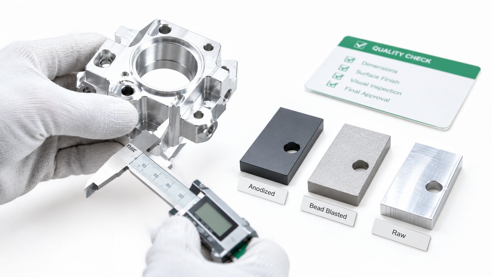
Inspect the characteristics that matter
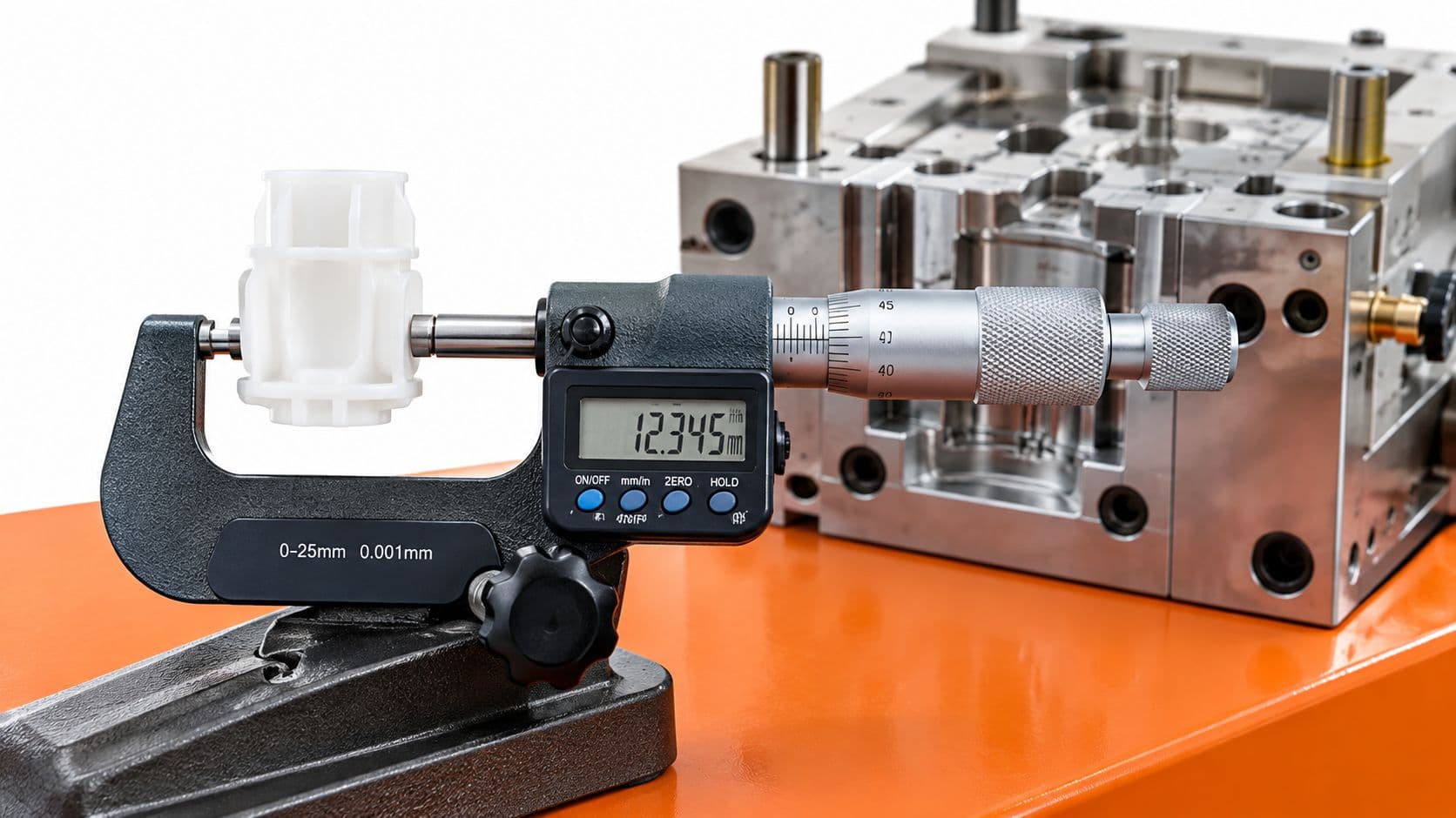
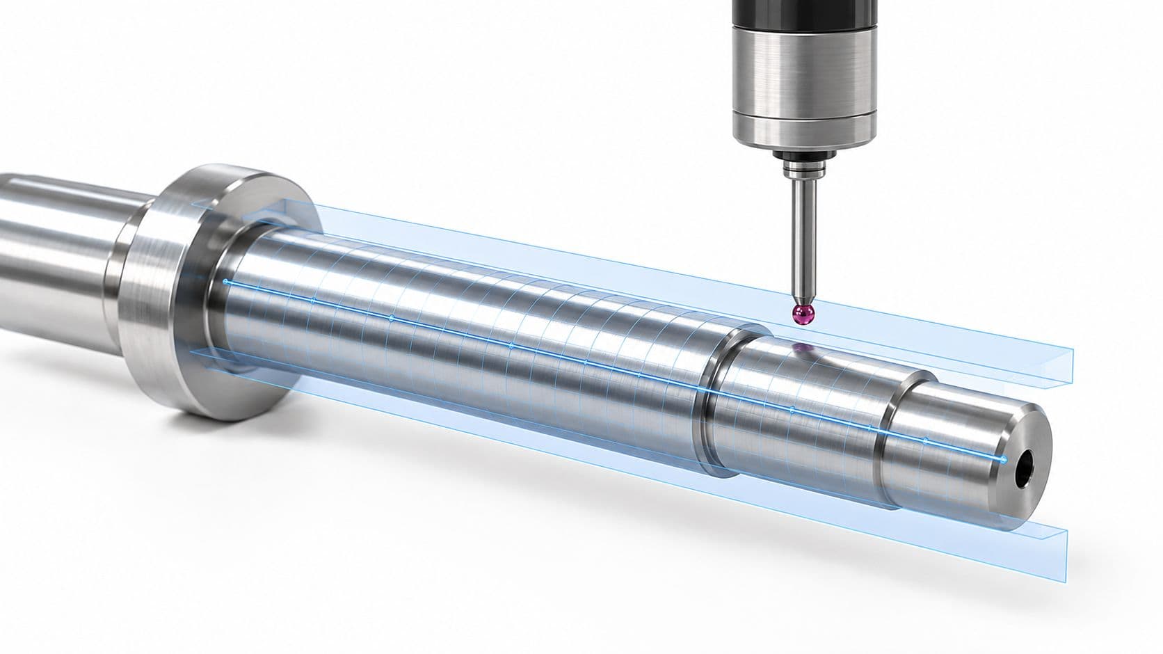
Inspection should follow the tolerance plan. Check critical bores, datums, interfaces, wall thicknesses, and positional relationships first. Use calibrated tools appropriate to the feature, from digital calipers and micrometers to gauges or a CMM inspection service when geometry and reporting requirements justify it.
Request an inspection report when traceability matters. The report should identify the part or batch, drawing revision, measured characteristics, nominal values, actual values, and measurement equipment or method. Keep photographs of the assembly and note any adjustment, force, binding, leakage, or unexpected contact observed during testing.
Interpret pass and fail honestly
A passing prototype confirms only the test conditions applied to that part. It doesn't prove production readiness, process capability, supplier repeatability, or scale-up economics. A machined prototype can pass while a molded design still has unacceptable draft, sink, warpage, or gate-related defects.
A failure is often more valuable because it identifies a likely production risk. Deliberately review wall thickness uniformity, draft angles, tolerance stack-up, and tool access for assembly. If the part fails, record the failure mode before changing the design. Otherwise, the team may fix the symptom and lose the evidence that would have exposed a broader manufacturing issue.
A prototype should leave behind a decision record, not just a part that someone can hold.
Moving From Prototype to NPI Without Losing What You Learned
The handoff from prototype to NPI is where many teams lose their most useful engineering knowledge. The prototype may prove that a mechanism works, but the supplier still needs to know which assumptions were tested, which dimensions were critical, which features were intentionally loose, and what changed during fabrication.
Create a knowledge package while the build is fresh. Include the released CAD and drawing revisions, material and finish choices, inspection results, assembly observations, supplier DFM comments, unresolved risks, and photographs of failures or modifications. Record why each decision was made, not only what the final drawing shows.
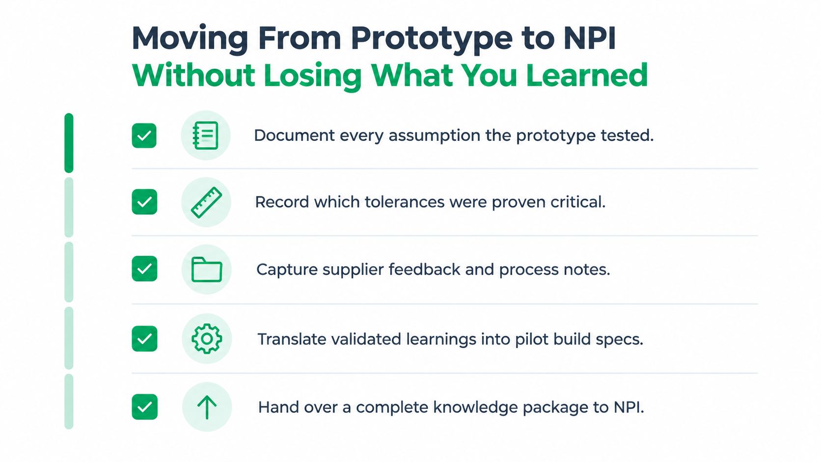
Convert prototype evidence into production controls
A production-intent drawing should distinguish proven requirements from inherited assumptions. If a loose tolerance worked during assembly, don't tighten it merely because an older drawing used a smaller limit. If a fit required selective adjustment, capture that fact and decide whether the production process should control the dimension, change the interface, or use a different assembly method.
Translate the findings into supplier-ready information:
- Critical features: Define the dimensions, datums, material properties, and inspection method that protect function.
- Process constraints: Capture draft, radii, wall thickness, tool access, fixture requirements, and setup assumptions.
- Acceptance criteria: State what constitutes an acceptable fit, finish, movement, seal, or cosmetic result.
- Revision history: Link every design change to the test observation or DFM finding that caused it.
- Pilot objectives: Specify what the NPI build must repeat, measure, or expose before wider release.
Choose the bridge to low-volume production
The next process doesn't always need to be final production tooling. Rapid tooling can produce molded parts in a production-like resin while keeping the commitment appropriate to an early build. Vacuum casting can support bridge quantities and appearance validation. Staged low-volume machining or sheet-metal supply can provide repeat parts while the design and process controls mature.
The transition should also preserve quality records. ISO 9001 supports structured quality management and traceability, while ISO 13485 is relevant to medical-device quality systems where controlled documentation and risk management are essential. The applicable framework depends on the product, market, and customer requirements, but the operating principle is consistent: maintain revision control, inspection evidence, approved materials, and a clear record of nonconformances.
Set the NPI handoff conditions
Before the pilot build, confirm that the team has:
- A locked validation requirement for each critical feature.
- A tolerance plan based on demonstrated functional need.
- Supplier-approved DFM changes and process assumptions.
- A defined inspection and reporting method.
- A schedule that includes rework, design changes, and process feedback.
Some products require “several prototypes, sometimes tens” before concept validation is complete, according to DFM guidance from Cortex Design. That isn't a failure of planning. It reflects the difference between proving an idea and proving that the idea can be manufactured repeatedly.
The NPI build should inherit the prototype's learning, not just its geometry. Keep the supplier conversation open, schedule pilot quantities around the risks that remain, and use every build to reduce uncertainty in a traceable way.
FIRMFG supports prototype development from CAD review through CNC machining, 3D printing, sheet metal, molding, vacuum casting, finishing, inspection, and low-volume NPI builds. Share your CAD files, validation goal, material requirements, and target quantity with FIRMFG to get manufacturing feedback that addresses tolerance, process selection, and the path from first part to repeatable production.