Injection Molding Inserts: Materials and Design Guide
The brass insert passes the pull-out test, but the housing still bows after cooling. Or your prototype mold fills cleanly, yet the deep core stays hot enough that operators can't shorten the cycle without marking the part. In both cases, the insert looks mechanically sound. The problem is what happens around it.
Injection molding inserts affect load transfer, melt flow, heat removal, and residual stress. Choosing a material or adding a deeper knurl won't solve every failure. The useful starting point is to decide whether you're designing an insert that stays in the product or an interchangeable insert that stays in the mold, then qualify the interface each one creates.
Table of Contents
- What Injection Molding Inserts Are and Which Type to Use
Match the insert family to its job
Choose by the failure you must prevent
How Inserts Control Cooling and Cycle Time- Separate material gains from channel gains
Insert Materials Compared for Heat and Wear- Read the table as trade-offs, not a ranking
Interface Failures and Their Causes- Diagnose the interface rather than adding more retention
Design Rules for Cooling, Clearance and Wall Thickness- Release the cooling design with its structural checks
Go or No-Go- Make the decision against the build's purpose
Validate Your Insert Design Before Cutting Tooling- Use a release sequence with measurable outputs
What Injection Molding Inserts Are and Which Type to Use
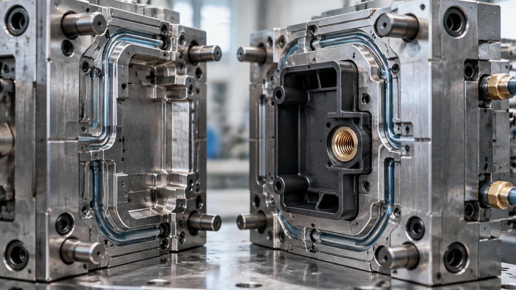
Say you're developing an electronics enclosure with threaded mounting points and a deep internal boss. The threaded brass components remain in the enclosure after molding. The removable core that forms the boss stays in the tool. Both are called inserts, but they solve different problems.
Insert molding places a metal or other preformed component in the cavity before injection. Plastic flows around it and creates an integrated assembly. Overmolding adds a molded layer to an existing substrate, often a previously molded plastic part. Neither term means installing a replaceable mold component.
A mold insert forms a localized cavity, core, feature, or cooling structure without requiring replacement of the complete mold. For the broader process context, the plastic injection molding guide explains how filling, packing, cooling, and ejection fit together.
Match the insert family to its job
- Press-fit metal inserts: Installed into molded features using interference, sometimes with knurling. These are a post-molding assembly option, not automatically an insert-molding operation.
- Threaded brass inserts: Provide reusable fastening points in electronics enclosures and medical device housings. Specify whether they're molded in or installed afterward.
- Undercut inserts: Use grooves, flanges, or other mechanical interlocks to resist extraction, such as a loaded attachment in an appliance handle.
- Pins and magnets: Require positive mold location and orientation control. Their position can matter as much as retention strength.
- Electrical contacts: Common in automotive connectors, where exposed contact surfaces must remain clean and conductive.
- Conformal-cooling mold inserts: Carry coolant through paths shaped around the cavity, rather than through straight drilled passages.
Conformal cooling became practical as metal additive manufacturing improved the ability to produce internal channels around complex molding surfaces. The PlasticsToday account of conformal-cooling development describes both that manufacturing progression and application-specific cycle improvements.
Choose by the failure you must prevent
For the enclosure, the brass insert needs torque resistance and protection from thread contamination. The boss-forming core needs stiffness, cooling access, and a serviceable mounting arrangement. Treating those as the same specification creates unnecessary compromises.
Match the insert to load direction first, retention second, and thermal demand third. A flange that resists axial pull-out may do little against rotation. A highly conductive mold core may solve a hot spot without being the right material for an abrasive gate region.
How Inserts Control Cooling and Cycle Time
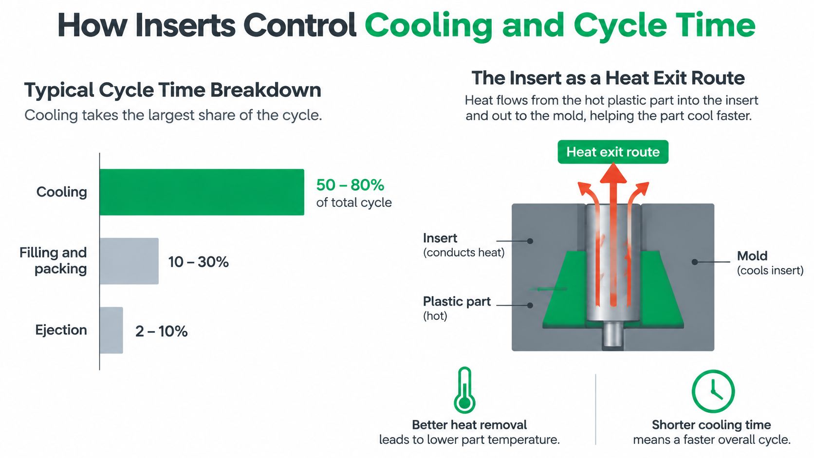
Cycle time is set where heat leaves most slowly. A mold insert works as a heat exit route: heat moves from the polymer across the molding surface, through the insert body and holder contact, then into the coolant. If seating, channel flow, or material conductivity is the bottleneck, improving the other stretches buys little.
Ejection readiness is a stiffness condition, tied to resin, wall geometry, packing history and allowable ejector loading. It is also an interface condition. A highly conductive core can cool a thick boss while a nearby thin wall is still shrinking, and that difference can leave residual stress or pull the part onto one side of the cavity. Metal and polymer expand at different rates, so clearance and contact pressure at the insert seat belong in the thermal review.
Separate material gains from channel gains
A 2024 comparative simulation in Progress in Additive Manufacturing found up to 47% cooling-time reduction for AlSi10Mg conformal-cooling inserts against a conventional 420 stainless-steel control, with specific energy consumption per molded part reduced by as much as 15% across the evaluated alternatives.
Treat those as simulation results for the tested arrangements. The case pairs alloy choice with cooling architecture, so credit belongs to the combined design, with material conductivity and channel geometry acting together.
Reported cooling and cycle results by insert change
| Case | What changed | Reported result |
|---|---|---|
| AlSi10Mg conformal insert vs 420 stainless control, comparative simulation | Material and conformal channels | Up to 47% cooling-time reduction |
| One insert application documented by PlasticsToday | Insert cooling geometry | Cooling time fell from 60 s to 40 s |
| Printed inserts compared with the preceding tooling arrangement in an industrial case | Additive insert construction | 22% total cycle reduction |
| Maraging-steel mold, conventional vs conformal, modeled | Channels follow cavity | 17 s to 13 s, 24% cycle reduction |
| Optimized insert channel profile in a tooling study | Channel profile and placement | About 6 s TPE cooling, 14.7 s total cycle |
The industrial and modeled cases summarized by PlasticsToday measure different outcomes. Cooling time is one component of total cycle time, and an optimized TPE result transfers poorly to a different resin or wall section. Use the cases to rank changes worth simulating, then let gate balance, warpage and ejection loads decide whether the saving survives tryout.
Practical rule: Improve the slowest heat path before paying for a more conductive material everywhere.
Find the section that delays ejection
Start with the thickest section, then check whether a deep core or poorly cooled pocket governs release. Estimate its cooling behavior using the intended resin and process conditions. Compare candidate insert materials and channel layouts against that region while holding the other assumptions consistent.
Check cavity balance at the same time. If one feed keeps a region hot while another freezes early, the insert may be correcting a flow problem with temperature and adding stress in exchange for speed.
Inspect the insert-to-holder contact as well. Poor seating, an interrupted contact surface, or coolant that bypasses the intended circuit can undermine an otherwise sensible thermal design.
Finally, compare acceptable parts per production period, beyond the shortest machine setting. A faster cycle that creates distortion, sticking, or inconsistent dimensions gives back more than it saves.
Insert Materials Compared for Heat and Wear
The insert is half of a metal-polymer interface. Its conductivity sets how fast the polymer skin freezes against it; its stiffness and thermal expansion decide how much the surrounding melt is constrained while packing and shrinking. A material that clears the hot spot can still leave a stressed boundary if it makes one side of the cavity solidify much earlier than the other.
Insert materials by thermal, wear and fit criteria
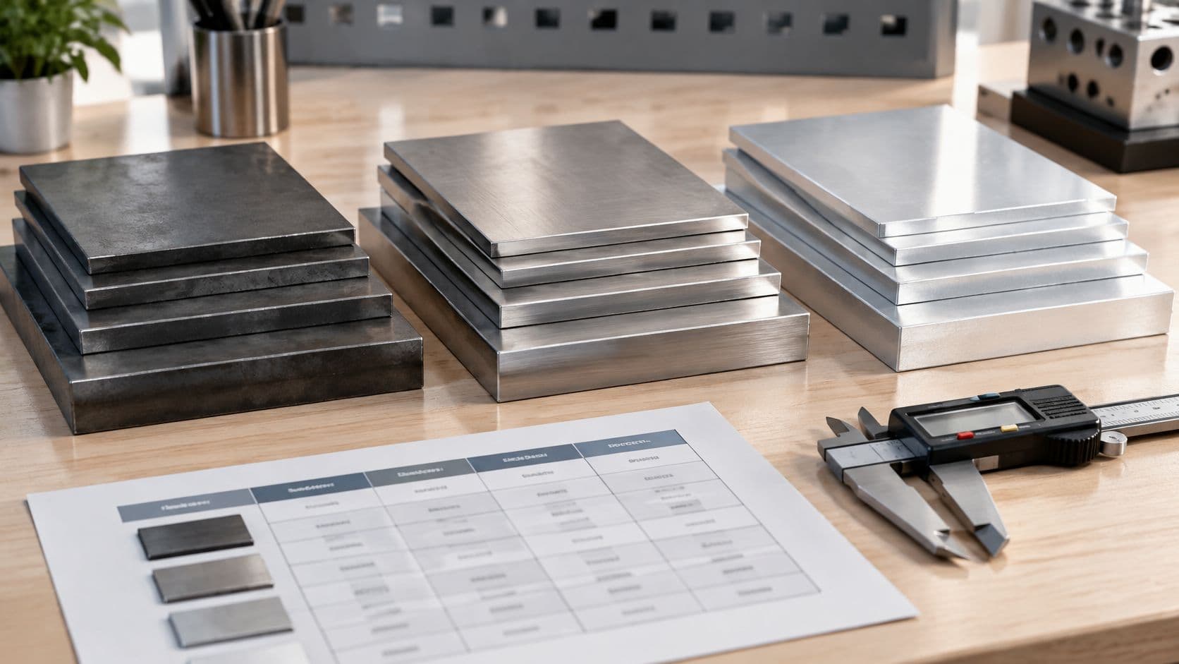
| Material | Thermal role | Wear / hardness role | Best fit | Main limit |
|---|---|---|---|---|
| H13 tool steel | Moderate conductivity, typically about 25–30 W/m·K | Durable hot-work steel; repairable and stable in abrasive duty | Standard cavities and cores exposed to substantial wear | Slower heat removal than high-conductivity alternatives |
| C17200 beryllium copper | High conductivity for a copper alloy | High hardness for a copper alloy; still check wear against steel | Localized hot spots, deep cores, thin tool sections | Higher cost than P20 or H13; handling and wear must be planned |
| Pure copper | Highest conductivity in this group | Low hardness; needs support and protection from flow and cleaning | Aggressive localized cooling where wear exposure is limited | Softness and deformation under service loads |
| Additive AlSi10Mg aluminum | Chosen for channel freedom more than bulk conductivity | Surface durability is build- and finish-sensitive | Prototype and bridge tooling with conformal channels | Wear and thermomechanical durability require qualification |
Use supplier-certified properties for the actual material condition. A handbook value for wrought stock does not automatically transfer to an additive insert, and an alloy designation alone does not define final hardness.
The Archives of Metallurgy and Materials comparison reports ejection-temperature times of 9.5 seconds for beryllium copper versus 12.4 seconds for tool steel in its evaluated case, and describes C17200 at approximately 105–125 W/m·K thermal conductivity and 38–45 HRC hardness. That combination explains why BeCu can pull heat from a compact core without dropping immediately to pure copper's softness.
Read the table as trade-offs, not a ranking
H13 tool steel is the sensible starting candidate where surface durability, structural support, and repairability dominate. Do not replace a durable steel insert only because another material conducts better. First prove that heat removal, not pressure balance or ejection geometry, is the limiting problem.
C17200 beryllium copper is strongest as a targeted hot-spot insert. Make it replaceable, seat it on rigid support, and define protective treatment around the actual resin exposure. The alloy also needs a machining and handling plan that matches shop controls.
Pure copper belongs where the thermal element can be supported and shielded. A backed chill block is a different job from a slender core facing abrasive melt flow.
Additive AlSi10Mg earns its place when the cooling path cannot be drilled conventionally. The molding surface, mounting faces, and sealing lands still need a defined finishing and inspection route before the insert is treated as production-capable.
Include the resin in the material decision
Glass-filled resin changes the wear question. So do corrosive processing conditions, sliding contact, and repeated polishing. Specify those exposures before approving coatings or a softer high-conductivity insert.
For a cosmetic housing, qualify appearance alongside dimensions. Faster local solidification can shorten the effective packing window near the insert and shift gloss, witness marks, or flow-junction appearance. The same mismatch can also leave the polymer more constrained around metal than the part drawing assumes.
Choose by the hot spot, resin abrasiveness, interface stress risk, and required production duty. Conductivity alone does not establish tool life.
Interface Failures and Their Causes
A molded-in metal component divides the space available to the melt. If the flow paths around it differ, the advancing fronts can reach opposite sides at different times and under different pressures.
A metal–plastic hybrid molding study in The International Journal of Advanced Manufacturing Technology found pressure differences of up to 15.16 MPa between opposite sides of the part when an insert asymmetrically divided the cavity. The study also identifies coupled effects from thermal expansion, conductivity, local flow resistance, solidification, and deformation.
Residual stress matters because the plastic and metal don't freely contract together. A component can meet its retention requirement while constraining the surrounding polymer enough to distort or crack it.
A mechanically secure insert can still fail the part.
Diagnose the interface rather than adding more retention
Insert interface symptoms, causes and fixes
| Symptom | Likely cause | Fix |
|---|---|---|
| Warpage toward the insert side | Asymmetric cavity pressure and thermal mismatch | Check gate balance; trial controlled insert preheating and revised local cooling |
| Sink mark near the insert | Slow local cooling, excess plastic mass, or uneven packing | Review section thickness, cooling access, and packing pressure and time |
| Cracking at the insert edge | Differential contraction and stress concentration | Round sharp edges; revise local constraint and provide relief where function permits |
| Insert rotation | Insufficient resistance to torque | Add suitable knurls, flats, or undercuts and verify surrounding plastic strength |
| Leakage around the insert | An interrupted sealing path or shrinkage gap | Define the sealing mechanism; revise fit, interface geometry, or a dedicated seal |
| Pull-out under load | Insufficient mechanical retention or failure of surrounding plastic | Add flanges or undercuts and test the complete joint after thermal exposure |
These are diagnostic hypotheses, not symptom-to-setting shortcuts. Warpage direction alone doesn't prove the insert side needs more cooling. Likewise, increasing packing pressure can worsen stress without correcting an unbalanced fill.
Check the shutoff and injection molding parting-line design when flash appears around an insert. Flash at the tooling interface and leakage through the finished assembly are different problems.
Change the priority with the inserted component
For stainless steel, investigate the local thermal behavior rather than assuming the insert rapidly removes heat. For aluminum or brass, check how strongly the component changes local cooling and how its expansion affects the joint.
For magnets, protect orientation and confirm allowable processing exposure with the component specification. For electrical contacts, protect the contact surface and support the component against displacement without sacrificing its functional geometry.
Mechanical anchoring, thermal compatibility, and flow symmetry aren't competing checkboxes. Their priority follows the failure mode. Check flow balance, then the thermal path, then retention, unless an obvious location or anchoring defect already explains the failure.
Design Rules for Cooling, Clearance and Wall Thickness
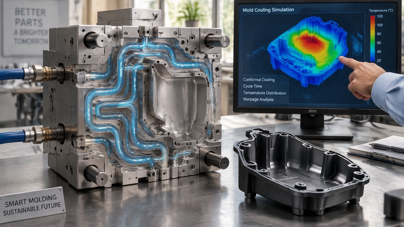
Evaluate the insert locally through transient thermal simulation, not only through an average mold-temperature plot. Include the insert, holder, cooling circuit, polymer section, and relevant contacts. A uniform-looking cavity average can conceal an overheated core tip.
A maraging-steel conformal-cooling study explains why maintaining channel proximity to the cavity improves thermal uniformity and reduces the hot spots associated with differential shrinkage. Use that principle to judge where conformal construction earns its complexity.
Release the cooling design with its structural checks
- Follow difficult geometry: Consider conformal channels around bosses, ribs, deep cores, and thick sections where straight drilling leaves inadequate coverage. Don't add curved passages where a serviceable drilled circuit already works.
- Size the complete circuit: Review channel diameter, spacing, pressure loss, coolant supply, and circuit balance together. A detailed internal passage is useless if the available supply can't deliver the intended flow.
- Protect the remaining tool wall: Check the ligament between the channel and molding surface against melt pressure, local stress, sealing, and manufacturing capability. Don't apply a universal minimum without the load case.
- Make cleaning possible: Identify connections, flushing access, and a method to confirm channel continuity before assembly.
The design review should also identify how an insert will be removed without damaging its holder. Accessibility matters when deposits, wear, or a product revision eventually require service.
Calculate fits at operating conditions
For a mold insert, specify the cold fit and evaluate differential expansion at operating temperature. An interference that looks acceptable on the bench can change after heating. Retention hardware must support process loads without preventing the intended thermal movement.
For a molded-in product insert, distinguish positioning clearance, plastic encapsulation, and sealing lands. They serve different purposes. Adding clearance indiscriminately can create a leak path or allow the component to shift.
Controlled preheating can reduce the initial temperature difference, but it doesn't eliminate an expansion-coefficient mismatch. Where the assembly permits, choose compatible materials or provide compliant geometry and local relief.
Place anti-rotation and pull-out features where the service load acts, with enough surrounding polymer to transmit that load. Include these interfaces in the DFM review for injection molding, rather than leaving them as isolated insert-detail drawings.
Release check: A cooling passage, retention feature, and sealing land must remain manufacturable when they occupy the same small region.
For additive metal inserts, put channel clearing, porosity inspection, surface finishing, and dimensional verification on the manufacturing route before approval.
Go or No-Go
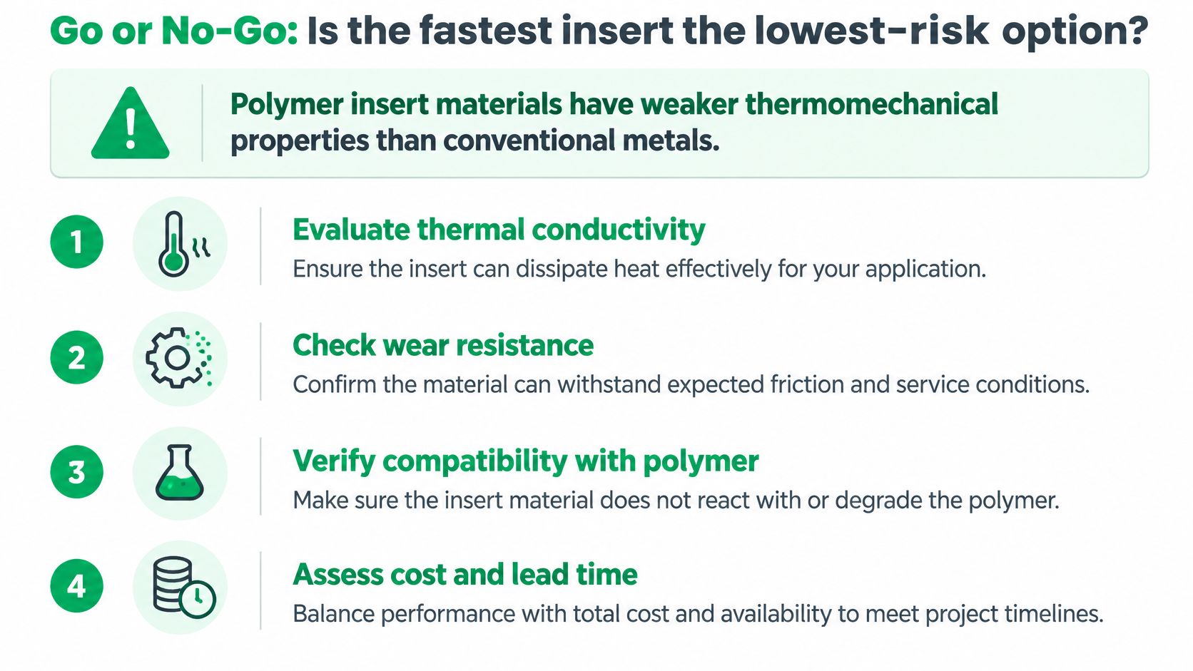
Is the fastest insert to manufacture the lowest-risk option for the build? Not necessarily. A short fabrication lead time is valuable only if the insert survives the required process and produces parts that answer the project's engineering questions.
Polymer tooling needs a particularly clear operating envelope. The published design guidelines for additively manufactured mold inserts describe poorer thermomechanical properties than conventional mold materials, recommend avoiding printed holes below 0.5 mm unless drilled afterward, and call for reinforcement of walls directly in the melt path or near the gate.
Make the decision against the build's purpose
Prototype with limited molding duty. Printed polymer inserts can be appropriate when geometry learning matters more than demonstrating a production-equivalent process window. Proceed only when resin temperature, pressure, feature support, and dimensional expectations fit the qualified tooling material.
Reject that route if a failed insert would invalidate a critical test or if the required geometry relies on unsupported, heat-sensitive details. A cheap replacement doesn't recover lost test time automatically.
Bridge production. Metal additive inserts are worth evaluating where otherwise inaccessible cooling controls part quality. Budget for heat treatment, finish machining, channel cleaning, and inspection. The printed shape isn't the finished tooling component.
Repeated low-volume production. Machined steel or aluminum can be the more manageable choice when conventional cooling and accessible geometry meet the requirement. Select between them using service duty and repair strategy, not a blanket assumption that either material always wins.
Compare total qualified cost
A 2024 study in Progress in Additive Manufacturing reported ULTEM 9085 granules at approximately €140 per kilogram, compared with €260 per kilogram for filament used to produce injection-molding inserts. Those feedstock prices don't establish the cost of an inspected, usable tool.
Include finishing, replacement inserts, machine interruption, scrap, and repeated first-article approval in the comparison. Difficult post-machining or weak gate-adjacent walls can move effort from tool fabrication into maintenance.
A 2026 systematic-review summary published by 3D Printing Industry describes 67 studies published from 2013 through 2024 on additively manufactured injection-molding inserts. That breadth is useful context, but it doesn't supply a universal safe shot count for your geometry.
- Go: The tool has a defined operating envelope, inspection plan, replacement strategy, and acceptance criteria tied to the build.
- No-go: The schedule assumes uninterrupted service without evidence that the material and geometry can withstand the molding conditions.
- Conditional go: The team can trial the insert, inspect it after thermal cycling, and stop before wear or deformation compromises the test objective.
Validate Your Insert Design Before Cutting Tooling
Release an insert design with evidence that connects the drawing to the molding process. A retention calculation alone doesn't qualify a molded-in component, and a thermal plot alone doesn't qualify a mold insert.
Use a release sequence with measurable outputs
- Confirm the material against the actual duty. Record the hot spot, resin abrasiveness, required production quantity, and supplied material condition. Identify whether the limiting concern is cooling, wear, stiffness, corrosion, or surface quality.
- Run transient thermal and flow analysis. Model the local insert geometry and cooling arrangement. For a molded-in component, evaluate flow splitting and pressure balance around it. Save the assumptions so the molding trial can test them.
- Define clearance and retention separately. Document operating-temperature fits, torque resistance, extraction loading, and the sealing method. Check the surrounding plastic, not just the strength of the metal component.
- Select the manufacturing route for the production scenario. Compare printed polymer, metal additive, and machined tooling against the required test or build. Put post-processing and inspection requirements on the purchase specification.
- Approve a first article and a durability check. Record measured dimensions against drawing tolerances under defined conditioning. Reinspect the part and insert after representative thermal cycling, then test the relevant function, such as torque resistance, pull-out, sealing, or electrical continuity.
Send a decision-ready package for quotation
Include the part model, insert drawing, resin requirement, critical tolerances, expected build quantity, and functional acceptance tests. Mark assumptions that still need trial confirmation rather than presenting them as settled requirements.
FIRMFG offers insert molding as part of its injection molding services, so this validated package can move directly into quotation. Validate the interface before cutting the tool. Changing a model is simpler than revising hardened geometry and qualifying the resulting parts again.
FIRMFG supports injection molding prototyping and low-volume builds, including insert molding and overmolding, with no minimum order. Visit FIRMFG with your part model, insert specifications, and validation requirements to request a quote; our engineers can recommend the resin grade, Shore hardness, and mold strategy for your functional and cosmetic needs.