Injection Molding Parting Line: How to Place It Right
You've got the part on screen, the cosmetic surfaces are approved, and tooling needs to start. Then the mold designer draws a seam across a sealing land or the front of the housing. Moving it looks simple in CAD, but the alternative may need a slide, a different gate, or a change to the snap fit.
An injection molding parting line isn't judged by visibility alone. Judge it by what it does to sealing, fit, optical performance, sliding contact, and inspection. A visible witness on a protected rear edge can be acceptable. An almost invisible step across a functional surface can make the part unusable.
Table of Contents
How to Locate the Parting Line Step by Step- Establish the direction and candidate boundaries
Mold Types and the Seam They Create- A housing and a side-hole clip
Flash Limits by Material and Gap Size- Translate the material risk into a requirement
Tolerances and Witness Lines Across the Split- Follow the dimension through the steel
Telling a Cosmetic Line from a Defect- Diagnose the pattern before adjusting the process
Weld Lines, Venting and Inspection Around the Split- Separate CAD prevention from tool validation
Confirm the Parting Line on Your First Article- Write an inspectable drawing note
Where the Parting Line Belongs on Your Part
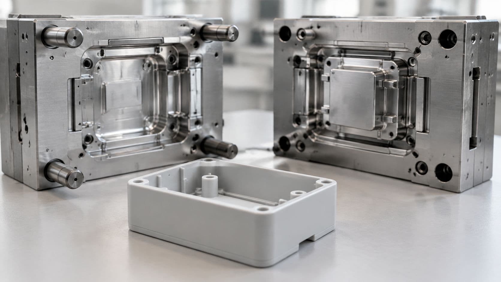
The parting line is the boundary where the cavity and core meet. The split-mold principle allows the mold halves to separate around the solidified component, as described in the injection molding overview. You're choosing where that boundary belongs, not designing a part without one.
Start by marking the protected features on your model.
| Part feature | Placement rule | Why it matters |
|---|---|---|
| Class-A cosmetic surface | Put the line on a hidden edge or non-visible face | Witness marks and polishing show on visible faces |
| Sealing face for gasket or O-ring | Keep the entire face on one mold half | Flash or mismatch can interrupt the seal path |
| Precision locating feature | Keep on one mold half | Mismatch shifts the datum |
| Snap fit or latch | Keep on one mold half where possible | Flash changes engagement force |
| Flat or simple-curved region | Preferred location for the line | Steel support and flash control are easier |
| Dimension crossing the split | Move the feature or loosen its tolerance | Inherits flash and mold-mismatch risk |
| Surface needing draft | Orient the line so ejection works | Too little draft causes drag marks |
Protect the contact, not just the appearance
A gasket face deserves more protection than an adjacent cosmetic wall. Don't assume the gasket will absorb a discontinuity because it compresses. Keep the sealing contact continuous and put any unavoidable witness outside that contact.
Apply the same reasoning to optical and sliding surfaces. A witness outside an optical aperture may be harmless, while one inside the working area can interfere with light transmission. On a sliding rail, locate the split away from the loaded bearing strip rather than relying on trimming to restore smooth movement.
Placement rule: Hide the line only after you've protected the surfaces that seal, locate, latch, transmit light, or slide.
A snap fit creates a useful trade-off. Moving the split away from its engagement face may improve consistency, but the resulting geometry still has to release from the mold. Review the latch orientation and opening direction together.
Make these decisions during DFM for injection molding, before machining begins. Moving the split later can mean reworking the cavity, core, side actions, and ejectors, not merely polishing away a seam.
How to Locate the Parting Line Step by Step
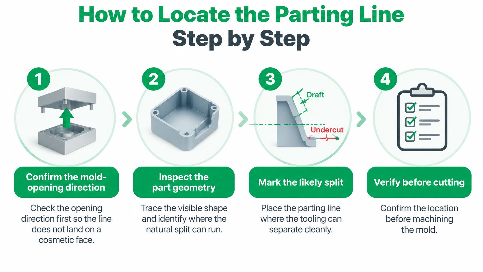
Choose the mold-opening direction before drawing the seam. Starting from the surface you want to hide can leave the tool designer with trapped geometry and no straightforward release path.
Establish the direction and candidate boundaries
- Confirm the opening direction. Put a draw-direction arrow in the CAD review and check the part from both mold halves. Don't use a cosmetic face as the reference just because it looks convenient. The tool must release every molded surface.
- Classify surfaces and map undercuts. Use draft analysis to distinguish surfaces that release toward the cavity, release toward the core, or trap steel. Inspect holes, hooks, returns, and recessed latches individually. An undercut needs a release strategy, which may be a slide, lifter, shutoff, or geometry change, not automatically a separate slide for every feature.
- Generate candidate edge loops. Trace plausible boundaries around the component and compare their projected areas normal to the chosen opening direction. Comparing loops without holding that direction consistent gives you a misleading result. Check topology as well as silhouette, particularly around openings and disconnected features.
- Select the workable loop. Favor the boundary that limits undercuts, side actions, and exposed witness marks without crossing protected features. Don't optimize seam visibility while ignoring a difficult shutoff or an inaccessible vent.
An academic parting-line determination method uses opening direction, surface orientation, topology, and projected edge-loop area. That's a useful basis for CAD checking, but an automatically generated loop still needs a functional review.
Turn the loop into tool geometry
- Extend the loop into a parting surface. Use flat or smoothly curved regions where practical. Inspect transitions closely. A neat line on the plastic model doesn't prove that the surrounding steel can be machined, fitted, and supported.
- Verify closure, draft, and vent access. Check that the halves meet without unintended gaps or interference. Add draft relative to the actual draw direction, then identify where displaced air can escape. A common slip is checking draft while treating vents as something to add after the tool is built.
- Review shutoffs and validate filling. Section the shutoff geometry, run filling analysis, and identify inspection locations before release. Don't approve a first article from an overall photograph. Examine the actual seam, functional contacts, and ejection condition.
A healthy first article has the witness where the approved drawing places it, an even transition along the split, and no need for hand blending on protected surfaces. If the tool needs routine cosmetic repair of a functional face, reconsider the design rather than normalizing the repair.
Mold Types and the Seam They Create
The mold architecture determines where steel separates, but a mold split isn't always an additional seam on the finished part. A runner-separation interface can exist without touching the component. Keep that distinction clear when comparing tooling proposals.
| Mold type | Parting lines | Seam effect | Tooling complexity |
|---|---|---|---|
| Two-plate mold | One main cavity/core split, which may be contoured | Simplest part seam in a basic configuration | Lowest for comparable simple geometry |
| Three-plate mold | Main split plus runner-separation split | Gate can move off the visible face; the extra split needn't mark the part | Moderate |
| Mold with slides or lifters | Additional interfaces where moving inserts form undercuts | Added witness where the moving insert meets adjoining cavity steel | Highest among these comparable configurations |
These are relative comparisons, not a universal cost ranking. Tool size, cavity geometry, gate arrangement, and moving mechanisms all affect the final design. Review the complete plastic injection moulding process rather than buying a mold type by name.
A housing and a side-hole clip
Consider a consumer housing with a Class-A front and a rear snap fit. A basic cavity/core tool with the split around the rear perimeter can preserve the front appearance without introducing another moving interface. But the rear snap must still release, and its engagement face needs controlled geometry.
If that snap traps steel, changing its orientation or opening the feature may be better than adding a lifter. The cheapest tool isn't useful if it produces inconsistent latch engagement.
Now consider a clip with a side hole. A slide can form the hole and withdraw before ejection, but it leaves a witness around the slide interface. Place that interface away from the clip's sliding or locating contacts. If the hole can become an open slot without losing function, a part redesign may eliminate the moving mechanism.
Removing a seam from a visible face often means accepting a witness elsewhere or paying for more complicated tooling. Decide which outcome serves the part.
Route boundaries along existing edges, steps, or deliberate design breaks where possible. Avoid casually crossing uninterrupted polished or textured faces, where matching the finish across separate steel surfaces becomes another acceptance problem.
Flash Limits by Material and Gap Size
A parting-line gap can leave a raised ridge on a sealing face, catch during assembly, or remain harmless on a nonfunctional edge. Set the flash limit by what the feature must do, not by whether the seam is visible.
The Fictiv injection-molding flash guide gives general flash acceptance below 0.004 inch, approximately 0.10 mm, and tighter tooling targets of 0.002 inch, approximately 0.05 mm, or less. These are general benchmarks, not automatic acceptance limits for every part.
| Material or condition | Typical flash limit or material consideration | What it means for the drawing |
|---|---|---|
| General mold flash acceptance | Below 0.004 in, about 0.10 mm | A common benchmark; define a tighter limit where function requires it |
| Precision tooling target | About 0.002 in, about 0.05 mm, or less | Requires tighter control of tool construction, alignment, and inspection |
| Low-viscosity PA6 | Needs a tighter shutoff than higher-viscosity resins such as PC or PC/ABS | Review narrow shutoffs and difficult transitions closely |
| Higher-viscosity PC or PC/ABS | Generally more resistant to entering small gaps than PA6 | Do not relax limits on sealing, fitting, or sliding features |
Flash height and mold gap are different measurements. A gap that allows resin to escape does not directly establish the height of the resulting flash.
Translate the material risk into a requirement
Material behavior is only one factor. Pressure, temperature, local steel support, and shutoff condition also affect flash, so resin type alone cannot set a reliable acceptance limit.
For PA6, specify close control at narrow shutoffs and transitions. With PC or PC/ABS, keep the requirement tied to function: a ridge on a gasket land or sliding contact may interfere even if it is acceptable on a nonfunctional edge.
Define whether flash is assessed as molded or after approved trimming. Set the limit at each relevant feature, especially where excess material could obstruct assembly, alter snap engagement, create a sharp edge, or disrupt a seal.
Tolerances and Witness Lines Across the Split
The 2025 NICE Rapid tolerance guide lists typical injection-molding tolerance as ±0.1 mm and very tight tolerance as ±0.025 mm, while noting that features crossing the parting line generally require looser tolerances. These are process-level reference values, not a promise for every feature, resin, and tool.
Tight dimensions require suitable tooling and cavity control. Apply them selectively to features that establish fit or performance, rather than copying the tightest value across the drawing.
Follow the dimension through the steel
Open a section view through the critical dimension and identify which steel surfaces form its endpoints. If the endpoints belong to different mold halves, include relative alignment in the tolerance assessment. A flash ridge can also change the result when a measuring contact lands on it.
Use this sequence when reviewing injection molding tolerances:
- Locate the datums. Confirm that the measurement references the intended molded surfaces, not a witness ridge.
- Check the steel ownership. Identify whether the relevant surfaces are formed together or across separate interfaces.
- Evaluate the assembly. Determine how much variation the mating component can tolerate.
- Assign the requirement. Keep the dimension within a mold half where practical, or agree on an achievable across-split band.
Don't solve an across-split dimension by tightening the title-block tolerance. That changes the purchasing requirement without changing the tool's ability to hold it.
Separate witness appearance from dimensional fit
A thin, uniform witness can be acceptable when its location, profile, and surrounding dimensions meet the drawing. Assess the molded surfaces on either side independently from the ridge itself. Otherwise, a harmless witness can cause a false dimensional rejection, or a measurement can miss a genuine step.
For a rapid-tooling or low-volume job, compare relocating the boundary with accepting a controlled witness. Extensive hand polishing may improve appearance, but it can also alter an edge or blur a feature that inspection depends on.
Drawing discipline: Specify dimensional fit and seam condition separately. Passing one doesn't establish that the other is acceptable.
Telling a Cosmetic Line from a Defect
Visibility isn't a reliable defect test. A prominent but controlled witness on a hidden edge may be acceptable. A small, intermittent ridge on a sliding contact may not be.
The Injection Molding Definitive Engineering Guide provides the tooling and process context for distinguishing a normal split witness from flash and alignment problems. Use appearance as a diagnostic clue, then verify the cause rather than repairing the tool from a photograph.
| Symptom | Likely cause | First action |
|---|---|---|
| Uniform, low-profile witness along the split | Normal meeting of mold halves with slightly rounded edges | Accept if hidden and within the drawing limit |
| Intermittent flash | Worn shutoff surfaces or insufficient clamping | Inspect shutoff contact and verify clamp force before repair |
| Flash that grows during a run | Tool wear or debris on the parting face | Clean and inspect the face; restore the shutoff only where damage is confirmed |
| Height mismatch across the split | Misalignment or worn dowels and guide pins | Check alignment and replace worn components |
| Line that differs by cavity | Uneven cavity pressure or thermal distortion | Compare cavities, then review filling balance and cooling |
| Sharp edge at the split | Excess flash, potentially aggravated by low material viscosity | Check gap and packing pressure; deburr only through an approved operation |
Diagnose the pattern before adjusting the process
Keep samples identified by cavity and production sequence. A defect isolated to a cavity calls for a different investigation from a condition appearing across the whole tool. Compare the actual molded surfaces, not just the apparent darkness of the seam under changing light.
Don't automatically increase clamp force or reduce packing pressure. Excess pressure can aggravate flash, but lowering it without checking the part can introduce another quality problem. Likewise, polishing a shutoff without understanding its contact condition can remove steel where you need support.
The sharp-edge row deserves particular care. Low viscosity increases susceptibility to flash, but a sharp edge alone doesn't identify the resin or establish the root cause.
Define acceptance by the contact condition
- Skin contact. Control sharpness and snagging, including after any permitted trimming.
- Optical surfaces. Define the working aperture and inspect the relevant optical effect, not merely general appearance.
- Sealing faces. Evaluate the contact path and validate sealing performance.
- Sliding interfaces. Check travel, friction, and interference under the intended loading.
- Snap features. Inspect engagement surfaces and verify assembly and release behavior.
Replace a vague request for a clean seam with location restrictions, flash and mismatch limits, tactile requirements, and an inspection method. A parting-line witness doesn't by itself prove structural failure. If the part fails mechanically, investigate the failure location, material condition, and molding process rather than treating every visible boundary as a crack.
Weld Lines, Venting and Inspection Around the Split
Moving the split won't automatically remove a weld line or burn mark. A parting line is a tooling boundary; a weld line forms where melt fronts meet without fully bonding. Treating them as the same defect leads to the wrong tooling change.
The Richland mold-design guidance describes how mold temperature, injection speed, pressure, and gate location affect weld lines. Relocating the split may improve steel support or vent access, but it can't compensate for an unsuitable gate strategy, trapped air, or unfavorable material temperature.

Separate CAD prevention from tool validation
| Stage | What to resolve |
|---|---|
| CAD and DFM | Protected surfaces, release geometry, steel support, intended vent access, and inspection access |
| Filling review | Predicted flow-front meetings, air traps, gate strategy, and likely vent locations |
| Mold trials | Actual filling behavior, burn marks, ejection damage, seam consistency, and functional performance |
| Production inspection | Cavity-specific variation, drift, and compliance with approved acceptance conditions |
Review predicted weld-line locations alongside the parting surface, vent paths, and ejector marks. A geometry change that helps release may still create an unfavorable flow pattern, so don't approve those decisions independently.
During trials, correlate process signals with measured part characteristics. Cavity-pressure and contact-temperature monitoring can support that investigation, but a process trace doesn't directly establish whether an edge is sharp or an optical surface is acceptable.
Use sensor-assisted checks where their relationship to the required characteristic has been validated. Keep direct inspection for conditions that the sensors don't measure. The practical division is straightforward: prevent predictable geometry problems before tooling, then verify process-dependent behavior in the actual mold.
Confirm the Parting Line on Your First Article
Freeze the intended location and acceptance requirements before machining, then approve the first article at the actual molded boundary. A drawing review establishes intent. A molded sample establishes whether the tool and process meet it.
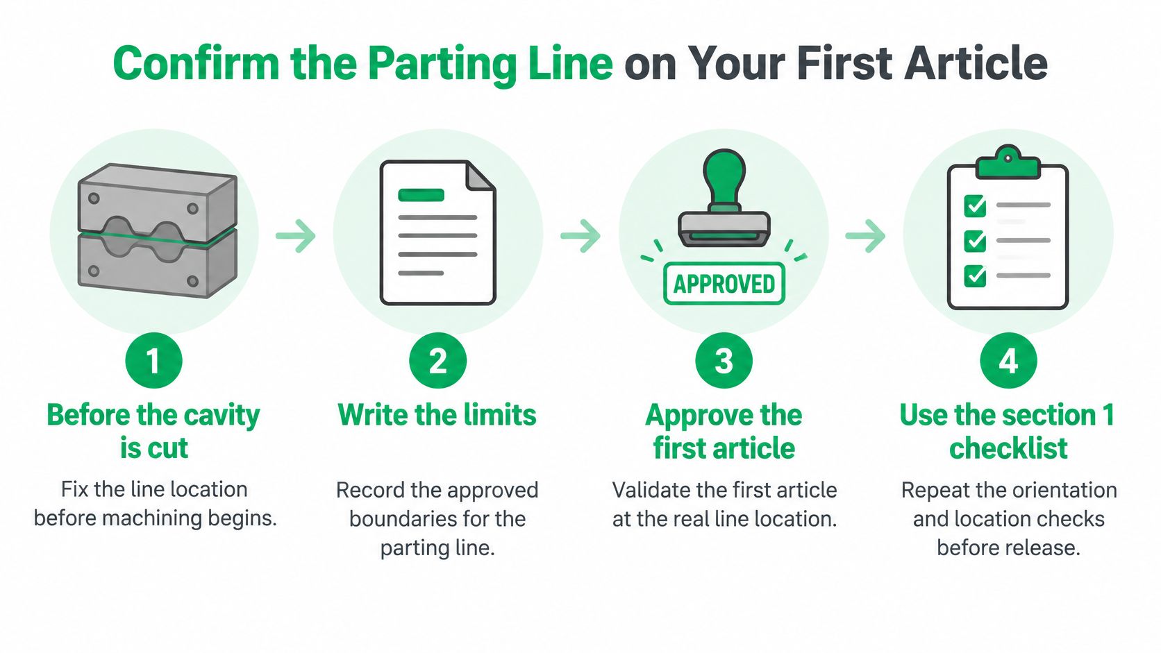
Write an inspectable drawing note
Use a note structure that assigns each requirement to a defined feature:
- Location. Parting line permitted within the marked rear-edge zone only, excluding designated sealing and Class-A surfaces.
- Flash. Apply the feature-specific maximum established on the drawing; identify whether trimming is permitted.
- Mismatch. State the allowable surface step separately from the flash requirement.
- Edge condition. Require a smooth contact edge without sharp projections or loose trimming residue.
- Inspection. Measure flash and mismatch optically; use gauge pins for relevant holes and a functional fixture for mating performance.
Replace those descriptions with approved drawing values before release. Gauge pins won't establish flash height, and a tactile check won't quantify mismatch.
If you accept a controlled witness to avoid extensive hand finishing, record that decision and retain an approved reference sample. Don't leave production inspectors to infer which cosmetic compromise the design team intended.
This week, send the part file, opening-direction arrow, protected-face annotations, and proposed seam limits for a pre-tooling review. Request a marked-up parting-line layout before authorizing machining.
FIRMFG offers plastic injection molding from prototype to production, including rapid tooling and batch manufacturing for low-volume production. Visit FIRMFG to discuss your part file, intended opening direction, and functional acceptance limits before committing to the mold split.