Insert Molding vs Overmolding Guide for NPI Success
A lot of NPI teams hit the same fork in the road at an awkward moment. The enclosure needs a threaded brass insert, or the handheld device needs a grip and a seal, and someone in the room says, “We can just overmold that.” Someone else says, “No, this is really insert molding.” The CAD keeps moving, tooling RFQs go out, and the decision gets reduced to metal versus soft-touch.
That shortcut causes trouble later. Parts fail for different reasons depending on how they're built. An insert-molded part usually lives or dies on insert location, retention geometry, and how the mold closes around a pre-formed component. An overmolded part usually lives or dies on substrate condition, material compatibility, and whether the second material bonds instead of peeling at the edge.
In practice, insert molding vs overmolding isn't a styling choice. It's a decision about bond mechanism, process control, and cost of poor quality. That's why two parts that look similar on a print can behave very differently in pilot builds.
Table of Contents
Understanding Insert Molding and Overmolding at a Glance- What insert molding actually does
Tooling Design Materials and How Each Bond Works- Insert Molding vs Overmolding Decision Matrix
- Mechanical lock versus material bond
- Tooling implications engineers feel immediately
- Material selection has to follow the bond logic
Tolerances Performance and Failure Modes to Plan For- What to inspect first
- Common failure modes by process
- Tolerance strategy should match the bond mechanism
- Validation plans that catch the real failures
Cost Lead Time and Prototyping for Low Volume Production- What usually drives cost in early builds
Real World Use Cases and When Each Method Wins- Cases where insert molding wins cleanly
How to Choose the Right Method for Your Next Build- Start with the interface requirement
Introduction Why Choosing the Right Molding Method Matters Now
A team is two weeks from freezing CAD for pilot tooling. The part needs to combine functions that used to sit in separate operations: retention, sealing, grip, conductivity, or thread strength. At that point, the discussion often gets reduced to a shortcut. Metal insert means insert molding. Soft outer layer means overmolding. That shortcut is where expensive mistakes start.
The decision is really about bond mechanism and how much process variation the design can tolerate.
Two parts can look similar on a print and still carry very different production risks. One depends on a mechanical capture that has to survive insert placement error, resin shrink, and pullout load. The other depends on one material bonding to another through heat, chemistry, surface condition, or a mix of the three. If the team picks the wrong mechanism, the problem usually does not show up in CAD review. It shows up at T1, or worse, during pilot when scrap starts to separate into patterns.
That matters even more in low-volume NPI. Early builds rarely fail because someone forgot the textbook definition of insert molding or overmolding. They fail because the chosen process was harder to control than the team assumed. Manual insert loading can introduce positional variation and handling damage. A second-shot or overmold process can look stable until substrate contamination or marginal material compatibility turns edge peel into a yield problem. The cost question is not only tooling price. It is scrap isolation, inspection burden, rework options, and how quickly the team can learn from first articles.
Where teams usually get into trouble
The failure mode usually traces back to one of three planning errors:
- The part needed mechanical retention, but the team treated it like a bonding question. That leads to weak capture geometry, poor insert support in the tool, or unrealistic pullout expectations.
- The part needed a dependable inter-material bond, but the team treated it like geometry alone would hold it together. That usually ends in peel, edge lift, or bond variation lot to lot.
- The team priced the molding step and ignored the cost of controlling it. Insert handling, part traceability, containment of bad lots, and destructive validation can outweigh a small cycle-time advantage.
I have seen teams recover from a slow cycle. Recovering from a bad bond assumption is harder, because it often forces changes to material, tool design, and validation plan at the same time.
A better starting question is simple: what is holding what, by which mechanism, and how controllable is that mechanism in the volume you plan to launch with?
Understanding Insert Molding and Overmolding at a Glance
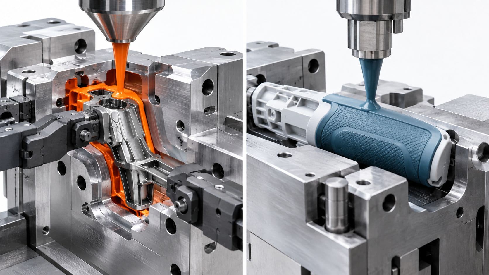
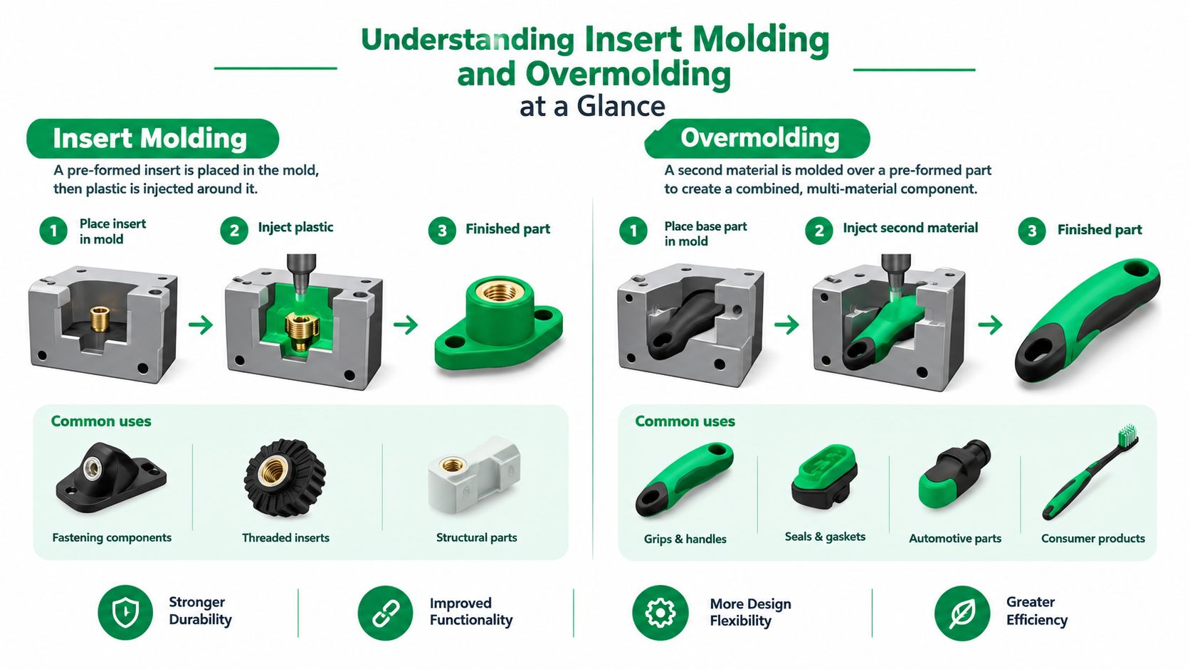
At a process level, both methods belong to the same injection-molding family. Both use molten resin, a mold cavity, and controlled cooling to create a finished part. The difference is what already exists in the mold before the shot happens.
What insert molding actually does
Insert molding places a pre-formed component into the mold before plastic is injected around it. That insert is often metal, and practical guidance points to use cases like threaded brass bushings, electrical contacts, and reinforcement pins. The interface is primarily mechanical, so insert position control and locking features matter if you want to prevent pullout under load (Meitu Engelhardt overmolding guide).
The basic workflow is straightforward:
- A pre-formed insert is loaded into the cavity manually or with automation.
- The mold must support and locate that insert consistently.
- Plastic flows around the insert and solidifies into the surrounding geometry.
- The finished part ejects with the insert captured inside it.
What changes from part to part isn't the sequence. It's how the insert is constrained, how shutoffs are designed, and how the geometry resists pullout or rotation after molding.
What overmolding actually does
Overmolding forms one material over an existing substrate, usually plastic over plastic or plastic over elastomer-compatible substrate. The substrate may come from a prior molding step, and the second shot creates the outer functional layer. This is the process teams reach for when they need grip, sealing, comfort, color separation, or local compliance.
The workflow usually looks like this:
- The first substrate is molded or prepared.
- That substrate is transferred or indexed into the next mold position.
- A second material is injected over selected areas.
- The final part leaves the process as a multi-material assembly.
Why the common shorthand isn't enough
People often reduce the topic to “insert molding is one-shot, overmolding is two-shot.” That misses the issue that drives most launch risk. Recent industry coverage points out that the selection hinge is usually bond mechanism and process risk, not a simplified count of shots. Insert molding generally relies on mechanical retention around a pre-formed insert, while overmolding often depends on chemical adhesion between materials and may require a separate substrate shot. That changes design rules, validation plans, and failure modes (Xometry comparison of insert molding vs overmolding).
If you don't know whether your part depends on retention or adhesion, you don't know which failure mode you're designing against.
Tooling Design Materials and How Each Bond Works
The cleanest way to compare insert molding vs overmolding is to ignore the usual marketing examples for a minute and focus on what the tool has to control. One process has to secure a discrete insert during mold closure and fill. The other has to create a reliable interface between two materials, often across complex geometry and varying wall sections.
Insert Molding vs Overmolding Decision Matrix
| Criterion | Insert Molding | Overmolding |
|---|---|---|
| Primary interface | Pre-formed insert captured by molded plastic | Second material formed over an existing substrate |
| Typical functional goal | Integrate non-plastic features such as threads, contacts, reinforcement | Add grip, sealing, compliance, color separation, or surface feel |
| Bond mechanism | Mechanical retention | Often chemical adhesion between materials |
| Tooling focus | Insert fixturing, shutoff control, anti-shift support | Substrate registration, second-shot coverage, interface design |
| Main validation concern | Pullout, rotation, insert position, flash around insert | Delamination, edge peel, incomplete bond, cosmetic mismatch |
| Process sensitivity | Insert loading accuracy and repeatability | Material compatibility, surface condition, substrate stability |
| Best fit in NPI | Parts that need functional embedded hardware in one molded body | Parts that need a second material for user interface or sealing |
Mechanical lock versus material bond
That bond difference changes everything.
With insert molding, the plastic doesn't need to chemically bond to the insert to succeed. It needs to trap it securely. That means the design should give the resin geometry to wrap around, resist rotation, and absorb load without concentrating stress at one thin ring of material.
With overmolding, the geometry still matters, but geometry alone won't save a bad material pair. If the bond depends on adhesion and the substrate doesn't support it, the part may pass basic handling and still fail later as peel, edge lift, or local separation.
Tooling implications engineers feel immediately
Insert molding puts more pressure on cavity-side mechanics. The mold has to locate the insert repeatably and survive cycles where a loaded insert can shift during closure. That's one reason low-volume jobs with manual loading can become expensive in hidden ways. The nominal process may look simple, but the failure path can damage tools as well as scrap parts.
Overmolding shifts complexity into the tool set and process chain. You may need a separate substrate shot, transfer handling, or a two-shot arrangement. That raises tooling and setup complexity, but it can reduce some of the risks tied to loose inserts moving inside the cavity.
Material selection has to follow the bond logic
For overmolding work, resin selection should start with compatibility, then move to feel, hardness, color, and appearance. For insert molding, resin selection should start with structural needs around the insert, shrink behavior, and whether the geometry around the retained component will stay dimensionally stable after molding.
A practical way to handle resin screening is to review the substrate and engineering plastic options early, especially when stiffness, impact behavior, and heat resistance are all in play. A broad material comparison such as this guide to injection molding thermoplastics is useful when the team is still narrowing candidates before formal DFM.
Practical rule: If the part must resist pullout, think like a retention designer. If the part must resist peel, think like a materials-and-interface designer.
Tolerances Performance and Failure Modes to Plan For
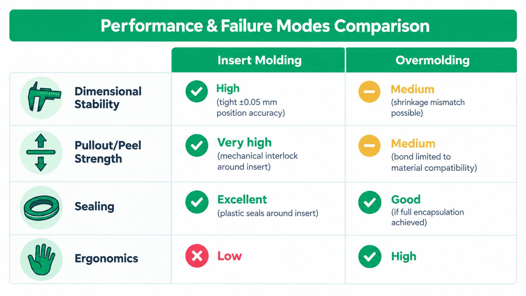
A pilot build can produce parts that pass incoming inspection and still fail in assembly a week later. That usually happens because the team measured the visible feature, not the feature that controls function. With insert molding and overmolding, the choice is often about which bond mechanism you can control more consistently at your target volume.
For insert molding, the control point is usually the insert's location and retention inside the shot. For overmolding, the control point is the interface between the substrate and the second material. Those are different failure systems, so they need different tolerance plans, inspection methods, and validation tests.
What to inspect first
In insert molding, inspect the insert datum before you focus on the outside plastic. A part can look clean and still be unusable if the threaded insert is tilted, the contact face is recessed, or a pin shifted enough to miss the mating stack. The plastic feature may be within print while the assembly-critical feature is not.
In overmolding, start at the bond line and at edge conditions where peel can begin. Cosmetic coverage does not prove adhesion, seal performance, or resistance to repeated flex. If the overmold is there for grip, isolation, sealing, or strain relief, inspect those functions directly.
Common failure modes by process
Insert molding usually fails through mechanical retention or position loss:
- Insert shift during molding
- Threaded insert tilt or rotation
- Pullout under torque or axial load
- Plastic bleed or flash that blocks a functional face
- Contact misalignment that affects conductivity or assembly fit
Overmolding usually fails through interface or interaction problems:
- Delamination at the bond line
- Peel initiation at thin lips, corners, or shutoff edges
- Voids or unbonded pockets at local features
- Substrate distortion that throws off the second shot
- Seal variation caused by poor seating or uneven compression geometry
A useful rule in NPI is simple. Insert molding asks, “Did the hardware stay exactly where the design needs it?” Overmolding asks, “Did the interface form the same way every cycle?”
Tolerance strategy should match the bond mechanism
Teams get into trouble when they apply standard dimensional inspection to a bond failure problem. Insert molding rewards tight control of datums tied to the insert itself: axis, height, rotation, and pullout resistance. Overmolding rewards control of surface preparation, substrate stability, local wall conditions, and bond-edge geometry.
That difference matters even more at low volume. In a high-volume program, the process usually gets enough repetition to expose weak controls quickly. In bridge production or early NPI, the bigger cost is often late discovery. Fifty parts with a hidden bond problem can do more damage than a visible short shot because they reach secondary ops, test, or customer builds before the issue is caught.
Validation plans that catch the real failures
For insert molding, validate around use loads and assembly alignment. Check positional repeatability of the insert, then test the failure mode that matters in service: torque-out, push-out, pullout, or electrical continuity under handling. If the insert sets the assembly stack, gauge the insert, not just the molded housing.
For overmolding, validate the interface under the conditions that break it. Use peel checks, flex cycling, leak testing, abrasion, or environmental exposure based on the part's job. A soft overmold that looks fully seated can still fail if the substrate moves too much in the second shot or if the bond edge gives the user a place to start lifting it.
Good DFM work catches a lot of this before steel. A focused review of shutoffs, substrate support, parting line location, draft, and wall transitions usually does more for yield than adding another cosmetic inspection step. This DFM for injection molding guide is a useful reference when the team is deciding which geometry needs process controls and which needs functional testing.
Cost Lead Time and Prototyping for Low Volume Production
A common NPI scenario looks like this: the part count is low, the geometry is still moving, and the team has one real question. Which interface is easier to prove and control before release. That question usually matters more than whether the part is called insert molded or overmolded.
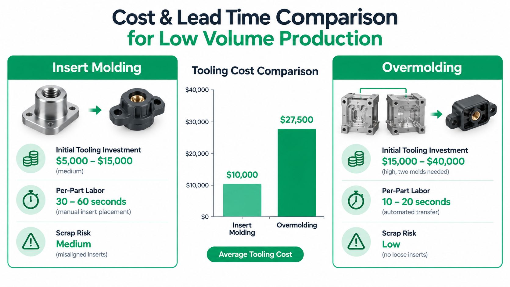
For low-volume work, cost-of-quality can outrun quoted tooling cost fast. A cheaper mold is not cheaper if the process depends on manual insert loading, extra inspection, frequent setup checks, or sorting after the run. A more complex mold is not automatically the wrong choice if it gives a cleaner bond mechanism and more repeatable yield.
What usually drives cost in early builds
The useful breakpoint is process stability at your expected volume. As noted earlier, insert overmolding often makes more sense below roughly 50,000 parts per year, while dedicated two-shot production tends to earn out at higher annual volumes. That is a planning guide, not a rule.
The cost drivers are different for each process.
Insert molding usually starts with lower program risk on the tooling side, especially if the insert is simple to fixture and easy to verify. It gets expensive when the cell depends on hand loading, insert orientation checks, slow cycle recovery after misloads, or conservative press settings to avoid shifting the insert during close. Scrap also hurts more when the insert is a machined or plated component instead of low-cost resin.
Overmolding often asks for more tool work up front because the substrate must locate consistently for the second shot and the bond area has to be protected from flash, mismatch, and handling damage. But if the bond is designed for repeatable mechanical lock or material compatibility, overmolding can remove secondary assembly labor and cut part-to-part variation in later builds.
Prototype the bond question first
Low-volume prototyping works better when the team isolates the failure mechanism before paying for production intent tooling.
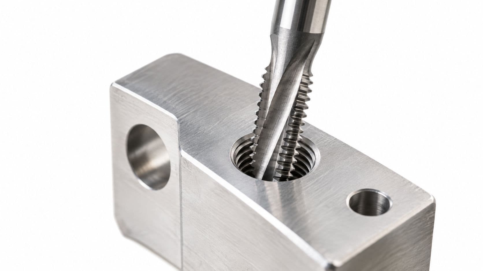
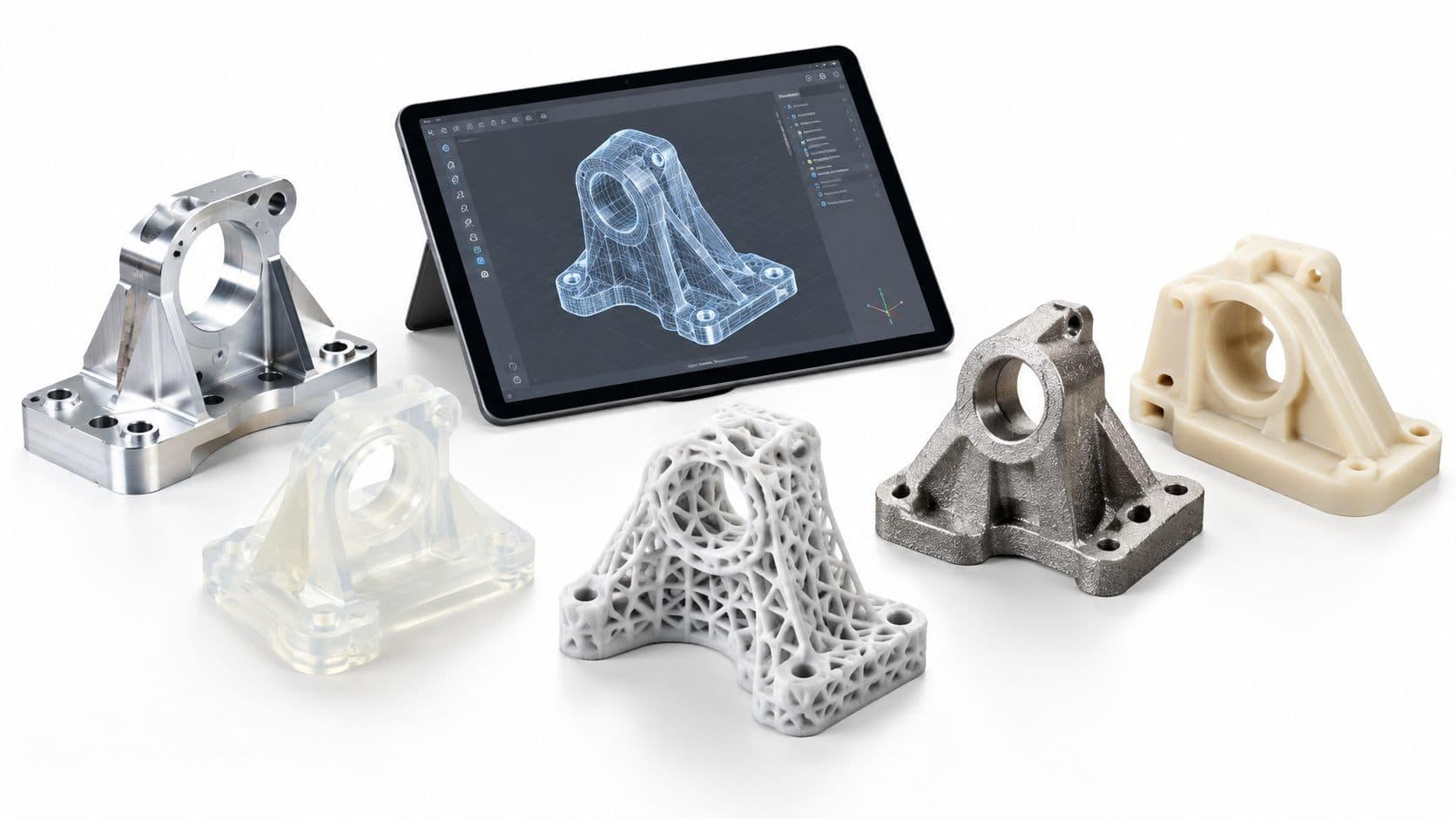
- Use CNC machining when the open question is insert fit, thread strength, stack-up, or local stiffness around a functional feature.
- Use 3D printing when the open question is hand feel, grip geometry, routing space, or package envelope.
- Use vacuum casting when appearance and limited functional testing matter more than production-grade interface control.
- Move to molded samples after the team knows what has to be proven at the interface, whether that is pullout strength, seal continuity, peel resistance, or substrate retention.
For bridge programs, this guide to low-volume injection molding options for prototyping and short runs is useful when deciding which iterations belong in molded parts and which should stay in faster prototype processes.
FIRMFG is one supplier option in this stage. The practical value is not that it offers every process. The value is that teams can test fit, geometry, and early interface assumptions across rapid tooling, low-volume molding, CNC machining, 3D printing, and vacuum casting before locking the program into a bond strategy that is expensive to change.
Real World Use Cases and When Each Method Wins
A team gets into trouble when it chooses the process by category label instead of by interface behavior. The better question is simpler. What has to happen at the bond line, and how much variation can the program tolerate in production?
Cases where insert molding wins cleanly
Insert molding is the stronger choice when the molded part has to capture a component that carries load, current, torque, or thread engagement. Threaded bushings, pins, contacts, shields, and stamped terminals fit here. The bond mechanism is mostly mechanical retention around the insert geometry, so the main controls are insert placement, preheat if needed, resin flow around the feature, and sink or flash that can shift the part from nominal.
That makes insert molding a good fit for connector bodies, sensor housings, surgical handles with metal cores, robotic end-effectors, and automotive parts with embedded hardware. If the program can hold insert location and verify pullout or torque-out performance, yield is usually more predictable than a two-material bond that depends on surface condition and process window.
Cases where overmolding earns its complexity
Overmolding wins when the interface itself must perform. That includes sealing lips, strain relief, impact isolation, grip zones, compliance for user comfort, or selective material coverage on a rigid substrate. In those parts, the question is not just whether a second material is present. The question is whether the substrate and overmold will bond consistently enough, across real production variation, to prevent peel, edge lift, leaks, or cosmetic mismatch.
That is why overmolding shows up so often in handheld medical devices, wearables, cable assemblies, power tool grips, and outdoor electronics. Analysts cited earlier put the global overmolding market at $12.3 billion in 2023 with 6.8% CAGR growth, which tracks with what many NPI teams are trying to do: reduce assembly steps while adding seal and ergonomic function.
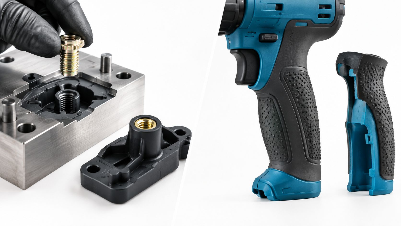
For low-volume builds, the decision often comes down to cost of quality, not piece price. Insert molding usually carries more risk in handling and placement. Overmolding usually carries more risk in bond consistency and cosmetic fallout. If the team can inspect insert position faster than it can prove a material-to-material bond, insert molding is often the safer launch choice, even for parts that could be designed either way.
The gray zone
Some assemblies need both. A handheld device may need brass inserts for fastening, a rigid molded housing for structure, and a TPE overmold for grip or sealing.
In that situation, avoid forcing one molded interface to solve every problem. Split the functions. Keep the production-critical interface on the mechanism you can control and verify with the least scrap risk. That usually leads to better first-pass yield than trying to make a cosmetic overmold also carry structural duty, or asking an insert-molded feature to provide compliance it was never built to deliver.
How to Choose the Right Method for Your Next Build
The selection framework is simpler than most make it.
Start with the interface requirement
Ask one question first: What is the interface supposed to do in service?
If it must retain a non-plastic feature such as a contact, bushing, or pin, start with insert molding. If it must create tactile value, sealing, or compliant coverage on a substrate, start with overmolding.
Then check controllability under variation
After that, review four practical filters:
- Failure modeAre you more worried about pullout and position error, or peel and delamination?
- Tolerance sensitivityDoes function depend on where an insert sits, or on whether two materials bond consistently along an edge?
- Volume and launch stageIs this a bridge build where manual handling is acceptable, or a scaled program where automation and repeatability justify more tooling complexity?
- Traceability and verificationCan you prove the critical interface is good every run, not just at first article?
That last point matters more now. Recent coverage shows the discussion shifting away from “Which process is simpler?” and toward “Which process is more controllable and data-verified under production variation?” For regulated and high-reliability programs, that's the right lens.
If the answer is still unclear, don't jump straight to steel. Run DFM on the critical interface, prototype the functional risk with the fastest suitable process, and define what a good part looks like before you quote production tooling.
FIRMFG supports that kind of decision path with CNC prototypes, 3D printing, vacuum casting, rapid tooling, and low-volume injection molding, including both insert molding and overmolding. If you're deciding which interface strategy is safer for your next build, visit FIRMFG to review options and get DFM feedback before you commit to the wrong mold architecture.