O Ring Groove Design
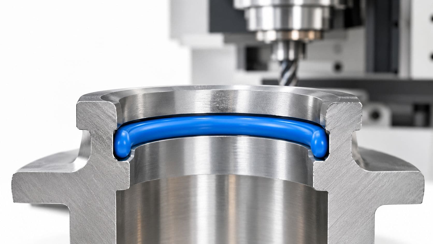
The pressure test starts, the gauge climbs, and a fine bead of fluid appears along the parting line. The o-ring is new, the material is appropriate, and the mating faces look clean. Then someone measures the machined groove and finds the actual problem: its depth was copied from an online drawing without checking the seal type, cross-section, or tolerance stack.
That failure is common because the o-ring gets treated as the design, when the gland controls the seal. Groove depth establishes squeeze, groove width provides room for deformation, and edge quality determines whether installation damages the elastomer before service even begins.
Reliable o ring groove design follows a decision chain. Identify the application, choose the cross-section, set the squeeze target, convert the target into depth and width, account for tolerances and clearance, then inspect the finished feature. The ratios are useful, but only after the engineer understands what each ratio is protecting against.
Table of Contents
- Why Groove Geometry Makes or Breaks a Seal
Start with the service condition
Treat the o-ring as part of a system
Understanding Squeeze and Groove Fill Targets- Calculate groove fill as a volume constraint
Choosing the Right Cross-Section and Standard Size- Use standard sizes where they solve the problem
Calculating Gland Depth and Width- Convert the ratio into dimensions
Designing Glands for Static Versus Dynamic Service- Static service favors stable contact
Tolerances, Surface Finish, and Machining Details- Protect the elastomer at every edge
Inspecting Grooves and Getting DFM Feedback Early- Use a short release checklist
Why Groove Geometry Makes or Breaks a Seal
An o-ring seals because it presses against the mating surfaces with enough contact force to close the leakage path. The gland creates that force. If the cavity is too deep, the ring barely contacts the opposing surface. If it's too shallow, the elastomer has nowhere to deform and may develop excessive friction, compression set, or installation damage.
A prototype can therefore fail even when the nominal o-ring size appears correct. A groove that looks plausible on a drawing may have the wrong depth for a dynamic rod seal, insufficient width for fluid swell, or a sharp internal corner that cuts the seal during assembly.
Start with the service condition
The first question isn't “Which groove table should I use?” It's “What does this seal do?”
A stationary enclosure cover, a hydraulic piston, a reciprocating rod, and a rotating shaft impose different demands. Pressure direction, movement, temperature, fluid compatibility, clearance, and assembly method all influence the gland. A face seal may need retention during lid installation, while a piston seal must tolerate movement without turning sealing force into excessive drag.
Practical rule: Never dimension the groove before classifying the seal as static or dynamic, then radial or face sealing.
Once the application is clear, the remaining choices become connected rather than arbitrary:
- Application type determines the acceptable squeeze range.
- Cross-section determines how much sealing material and radial space the design needs.
- Groove depth converts the squeeze target into a machined dimension.
- Groove width controls fill and gives the elastomer room to expand.
- Clearance and tolerances determine the worst-case installed condition.
- Inspection confirms that the manufactured gland matches the design intent.
This is why a dimension table alone isn't enough. Two grooves with similar widths may perform differently because one serves a static face seal and the other a moving piston. The correct dimension is the result of the entire chain.
Treat the o-ring as part of a system
The elastomer's hardness, chemical resistance, and swelling behavior still matter, but those properties can't rescue a badly proportioned gland. An otherwise suitable seal can leak from under-compression or fail early from over-compression.
The useful mindset is simple: the o-ring supplies the elastic element, while the groove controls how that element behaves. Design the cavity around the actual motion and pressure condition, not around a convenient drawing found in a catalog.
Understanding Squeeze and Groove Fill Targets
A groove can match a catalog dimension and still leak after assembly. The usual cause is a poor relationship between two design variables: squeeze and groove fill. Set those values before finalizing the gland, because they determine both sealing contact and the space available for elastomer movement.
Squeeze is the reduction in the o-ring's cross-sectional height after installation. That reduction generates contact force against the mating surfaces. For a radial gland, calculate it from the free cross-section and the installed gland height:
Squeeze (%) = (o-ring cross-section − gland height) / o-ring cross-section × 100
Use nominal dimensions for the first check, then repeat the calculation with the tolerance limits. A groove that is slightly too shallow can create excessive compression, while a groove that is too deep can leave the ring with insufficient contact.
The design ranges depend on the application, but their purpose is consistent. Static service generally accepts more compression because the ring does not slide across the mating surface. Reciprocating service needs a controlled contact force, since excess compression raises friction, heat, and installation effort. The technical o-ring groove guidance provides practical design guidance for setting that relationship.
Under-squeeze is a direct leak path. The ring may lose contact as pressure changes, hardware deflects, or dimensions move toward a tolerance limit. Over-squeeze can flatten the ring permanently, increase assembly force, and accelerate compression set. The percentage matters because it predicts these failure modes, not because a single value guarantees performance.
Calculate groove fill as a volume constraint
Groove fill is the portion of the available gland volume occupied by the o-ring. It must include room for the elastomer to deform under compression and accommodate thermal expansion or fluid swelling. Published groove design ratios commonly place fill around 60% to 85%, as shown in published groove design ratios.
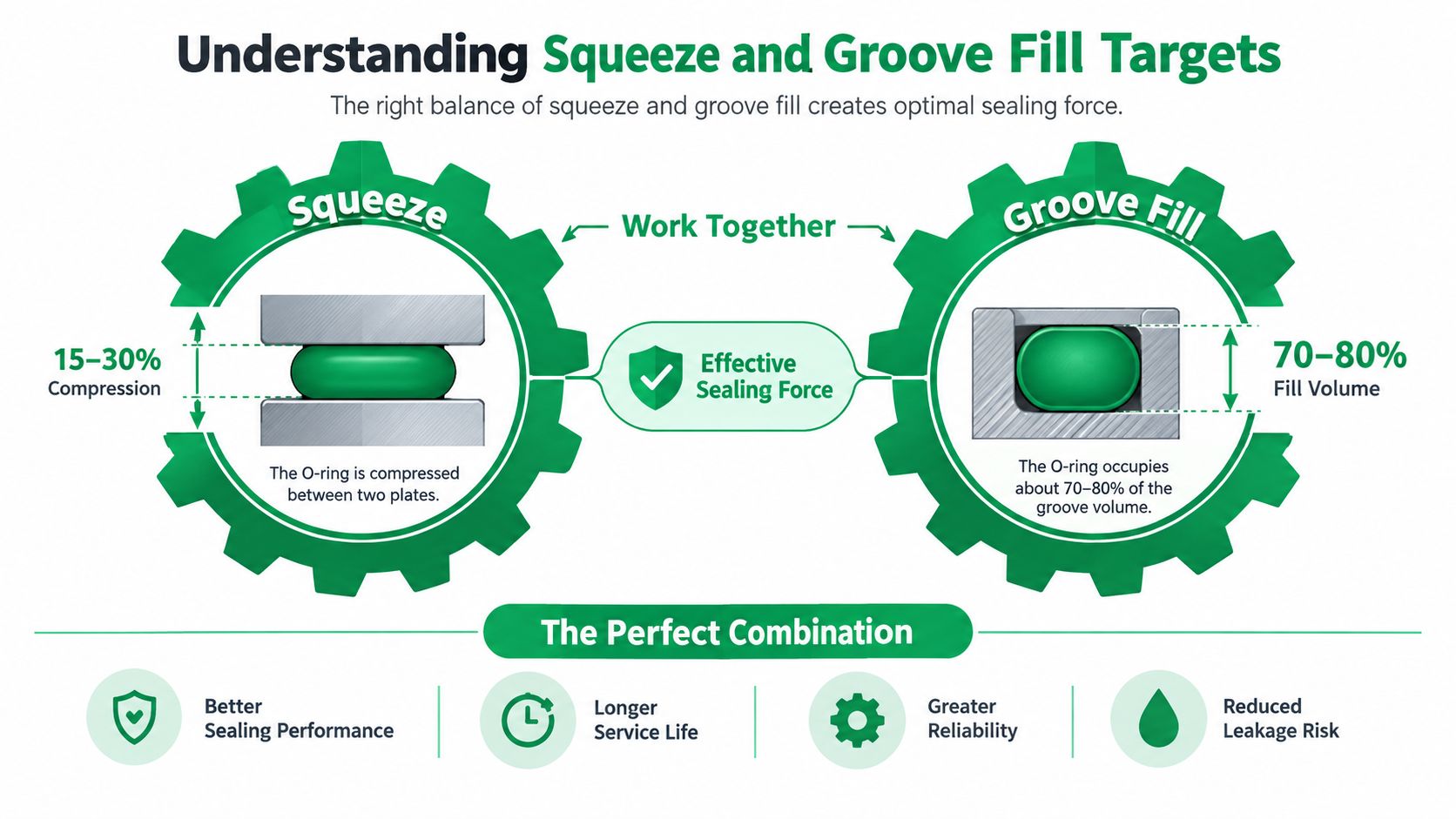
Excessive fill can hydraulically lock the ring. Swollen rubber then has nowhere to move, increasing distortion and assembly damage. Low fill may leave the ring poorly retained, allowing movement under pressure or motion even when the squeeze calculation looks acceptable.
Design rule: Use squeeze to create contact force. Use groove volume to give the compressed elastomer somewhere to go.
Check both values at nominal dimensions and at the worst tolerance conditions. The finished design should provide a controlled operating window, not one attractive number on a CAD screen.
Choosing the Right Cross-Section and Standard Size
A groove can be dimensionally correct and still fail because the selected o-ring section is wrong for the hardware. Cross-section determines the available sealing material, gland footprint, sensitivity to surface defects, and the space the assembly must reserve.
A small cross-section suits compact hardware, narrow radial envelopes, and static face seals. It also leaves less material to bridge scratches, absorb dimensional variation, or maintain contact when parts move slightly. Installation damage becomes more likely if the ring passes over threads, ports, or sharp transitions.
A larger cross-section gives more material and usually tolerates imperfect surfaces better. The trade-off is a larger radial or axial package, a wider groove, stronger surrounding hardware, and more control of installation stretch. Extra rubber does not compensate for inadequate clearance or a poorly supported pressure boundary.
Use standard sizes where they solve the problem
For many industrial assemblies, an AS568 dash-number size is the practical starting point. Standard sizes simplify sourcing, replacement, inspection, and tooling. They also reduce dependence on a single supplier during production support.
Choose a custom size only when the envelope, pressure boundary, or mating geometry rules out a standard ring. Restricted packaging, an unusual face-seal diameter, or a specialized production requirement can justify it. A custom section should document a real hardware constraint, not correct a groove that was dimensioned poorly.
Cross-section also determines which retention geometries are practical. Dovetail grooves generally suit larger-section o-rings. Technical guidance recommends them only for cross-sections of at least 0.139 inch, or 3.53 mm, as described in the o-ring groove design reference. The retention features consume space, so a smaller ring may leave too little elastomer for reliable contact after the groove is formed.
Match size to the real hardware
A compact electronics enclosure may favor a small standard section in a static face seal. A hydraulic piston often provides more room for a radial gland and may justify a larger section when clearance, pressure, or surface condition demands it.
Check the complete assembly before selecting the ring: gland envelope, mating clearance, pressure direction, installation path, hardware stiffness, and every edge the elastomer must cross. Confirm the ring can be installed without twisting, nicking, or excessive stretch.
If a standard size satisfies those constraints, it usually offers the cleaner engineering and supply path. If it does not, record the reason for the custom choice before setting squeeze, groove ratios, and tolerances. That decision chain prevents a convenient catalog size from dictating a groove the hardware cannot support.
Calculating Gland Depth and Width
Once the application and cross-section are set, gland design becomes a controlled dimensional calculation. The starting relationship is simple: groove depth is the o-ring cross-section minus the desired installed compression. Every later check should confirm that this nominal geometry still works at tolerance extremes.
Published design guidance commonly places static groove depth near 0.78 times the o-ring cross-section and dynamic groove depth near 0.90 times the cross-section. Groove width is commonly around 1.30 to 1.50 times the cross-section, depending on the application, as described in o-ring gland design guidance.
Convert the ratio into dimensions
Use this sequence:
- Select the o-ring cross-section, abbreviated as CS.
- Choose the application-specific squeeze target.
- Set nominal groove depth from the selected depth ratio.
- Set groove width to provide the required fill and deformation space.
- Check gland volume, mating clearance, and pressure direction.
- Recalculate with the machining and hardware tolerances applied.
The ratios are useful starting points, but each one has a failure mode if applied without checking the assembly:
| Application | Groove Depth Ratio (× CS) | Groove Width Ratio (× CS) | Failure mode if violated |
|---|---|---|---|
| Static service | 0.78 | 1.30 to 1.50 | Depth too shallow can cause over-squeeze and compression set. Width too narrow can restrict deformation and increase assembly damage. |
| Dynamic service | 0.90 | 1.30 to 1.50 | Depth too shallow can increase friction and wear. Width too narrow can trap the ring against the sidewalls. Width too wide can reduce retention and permit movement. |
The final gland must also account for pressure, fluid exposure, thermal change, surface condition, and clearance. A ratio does not compensate for a housing that distorts under load or a mating part that closes unevenly.
Worked example with a 2 mm cross-section
Take a 2 mm cross-section o-ring in a static face seal. Using a static depth ratio of 0.78, calculate the nominal groove depth as follows:
2.00 mm × 0.78 = 1.56 mm
The nominal squeeze is then:
2.00 mm minus 1.56 mm = 0.44 mm
Relative to the cross-section, that produces 22% squeeze, within the common static radial benchmark of about 15% to 25% described in neutral groove-dimension guidance.
For width, apply the selected ratio range:
- 2.00 mm × 1.30 = 2.60 mm
- 2.00 mm × 1.50 = 3.00 mm
A nominal width between 2.60 mm and 3.00 mm lets the designer balance fill, installation behavior, and expansion space. Use the narrower end only when swelling and thermal growth are limited. The wider end provides more room for deformation and volume change.
Check what the dimensions do
Groove depth does not determine installed squeeze by itself. The opposing surface, bore or shaft diameter, component flatness, and part tolerances also control compression. A shallow cut raises compression. A deep cut lowers it.
For a production drawing, identify the dimensions that control sealing height and inspect them as functional features. A nominal CAD measurement is not enough if the machinist must infer which surface establishes the final seal gap.
Designing Glands for Static Versus Dynamic Service
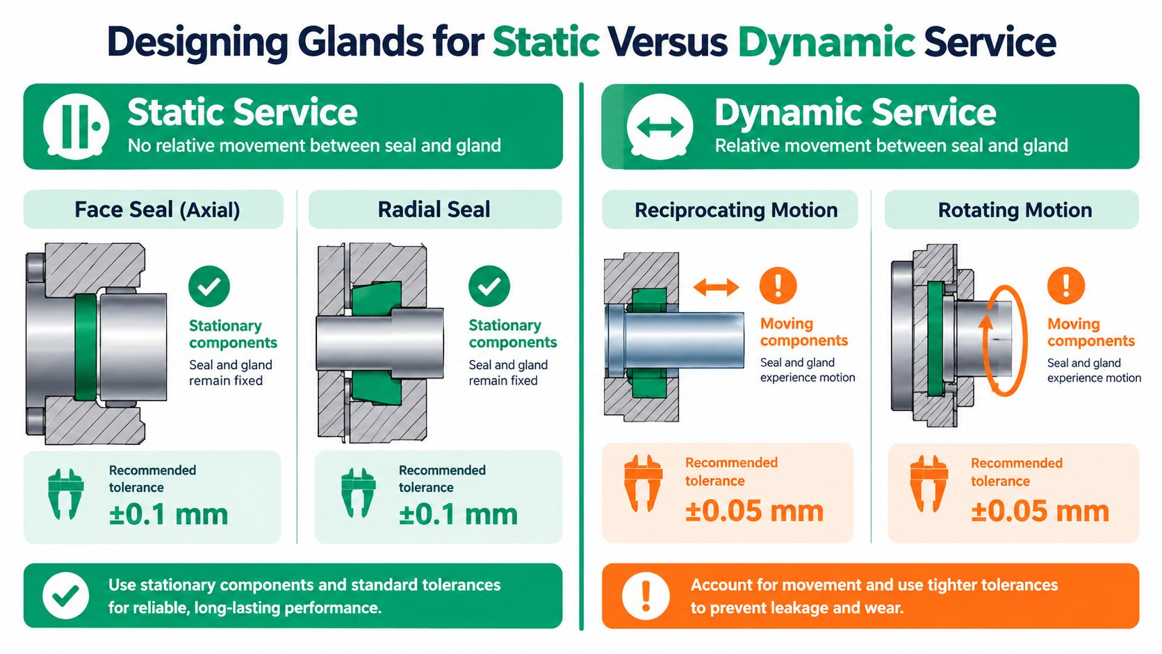
A cover seal that never moves and a rod seal cycling through a cylinder may use the same o-ring concept, but their failure risks differ. Static glands prioritize stable contact, retention, compression-set resistance, and safe assembly. Dynamic glands must also control friction, wear, lubrication, eccentricity, and repeated deformation.
Static service favors stable contact
A static face seal sits between opposing axial surfaces. Pressure can drive the ring toward one side of the gland, so groove location and retention should match the pressure direction. The ring must remain seated while a cover drops vertically or a flange rotates into place. Poor retention can displace the seal before the fasteners establish the final joint.
A static radial seal sits around or inside a cylindrical interface. The groove may be cut into a housing bore, shaft, or piston, depending on access and the selected design standard. The component carrying the groove matters less than the resulting radial compression and the way pressure loads the ring.
For static service, a typical squeeze target is 15% to 25%. A reciprocating seal commonly uses 8% to 16%, reducing friction and wear while retaining contact. Groove fill is generally kept around 60% to 85% so the elastomer has room for thermal expansion, swelling, and deformation. These benchmarks are summarized in the accompanying static and dynamic gland design infographic. Too little squeeze permits leakage. Too much raises contact resistance and accelerates compression set.
The design decision is therefore application first, ratio second. Set the service type, choose the squeeze target, then size the gland so the fill and clearance support that target.
Dynamic service spends sealing force carefully
A hydraulic-cylinder piston shows the trade-off clearly. The piston must maintain contact with the bore while moving, yet excess squeeze produces drag, heat, and wear. Groove geometry, mating-surface condition, and lubrication retention must work together for the operating cycle.
A rod seal faces greater installation and alignment exposure. The rod can introduce eccentricity, and its repeated passage can abrade an edge or pull the elastomer into a clearance gap. A gland that performs well in a stationary enclosure may fail quickly on a reciprocating rod when squeeze is too high, lubrication is poor, or motion exceeds the available clearance.
Check the complete motion system, including rod or piston runout, bore condition, clearance, pressure cycling, and extrusion risk. The groove cannot compensate for uncontrolled movement or an unsuitable mating surface.
For early prototypes, a manufacturing partner can confirm whether the proposed geometry fits the available process. FIRMFG's rapid prototyping services support CNC-machined metal and plastic parts for design validation, allowing physical checks of the sealing interface before selecting the production process.
Tolerances, Surface Finish, and Machining Details
A groove can match its nominal depth and width yet leak during the first assembly. The usual causes are sharp edges, burrs, tool marks, uncontrolled flank angle, or tolerances that push installed squeeze beyond its workable range. Check those failure modes while choosing the geometry, not after machining.
Use a rectangular groove unless the application gives you a reason to do otherwise. It is easier to machine, inspect, and dimension. A flank taper of up to 5 degrees can support production and release, but the sealing edges must remain free of features that could nick the elastomer. Keep the groove function clear: retain the ring without letting the taper alter the sealing volume or create an installation hazard.
Protect the elastomer at every edge
Round internal corners instead of leaving sharp intersections. Corner radii around 0.1 to 0.2 mm reduce cutting risk while remaining practical for machining. The radius must still fit the available cutter and must not reduce the effective gland depth or usable width.
Deburr every edge. A small raised burr can cut the ring as it passes over a bore, shaft, thread, or port. Control the deburring operation so it removes the burr without turning into uncontrolled edge breaking. Excessive chamfering changes the groove geometry and can reduce support at the sealing edge.
Surface finish must suit both movement and lubrication. A rough mating surface can abrade the elastomer and form leakage paths. A very smooth dynamic surface may retain too little lubricant. Use FIRMFG's surface roughness chart when comparing machined finishes, and review Rz or Rt alongside Ra because isolated peaks and valleys may remain hidden by an average value.
Build tolerances around worst-case squeeze
Check groove depth, groove width, mating diameter, flatness, concentricity, and o-ring cross-section variation together. The deepest groove combined with the most permissive mating condition can leave the ring under-squeezed. The opposite tolerance stack can over-compress it, increasing assembly force and accelerating wear or compression set.
Identify which surfaces control sealing. Place those dimensions on the drawing, define the edge condition, and specify a burr-free groove. A machinist can meet every numerical dimension and still leave an edge that damages the seal if the drawing does not address it.
Manufacturing insight: A tolerance has value only when the inspection method can measure the feature that controls sealing.
Machining access also affects cost and repeatability. A three-axis setup may produce a clean open groove, while a deep internal gland or angled feature may require another orientation or process. Resolve that constraint before release, so the quotation reflects the actual setup and the finished feature remains inspectable.
Inspecting Grooves and Getting DFM Feedback Early
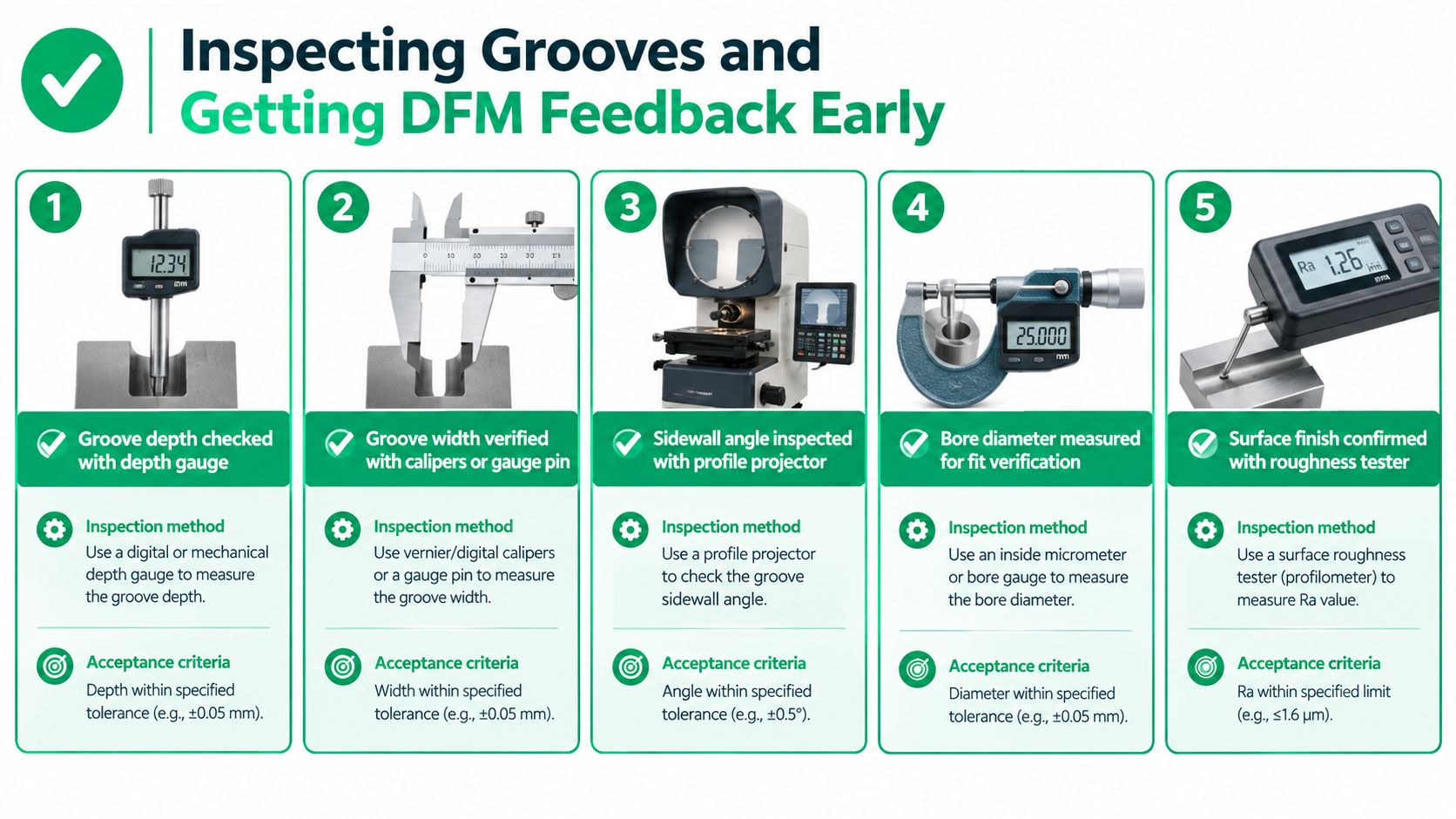
Inspection should verify more than length, width, and depth on a drawing. The groove has to be dimensionally correct, accessible to the o-ring, free from damaging edges, and consistent with the mating hardware.
Use a depth gauge to check groove depth. Verify width with calipers or a gauge pin, selecting the method that best suits the feature geometry. Inspect sidewall angle with a profile instrument or a cross-sectioned test piece, particularly when a tapered flank affects usable volume or retention.
Use a short release checklist
Before approving the gland, confirm:
- Application: Static or dynamic, radial or face, with pressure direction identified.
- Cross-section: Standard size selected where practical, with the reason documented for any custom section.
- Squeeze: Target calculated from installed geometry, then checked at tolerance extremes.
- Fill: Groove width leaves deformation room instead of trapping a swollen or expanded ring.
- Clearance: Mating bore, shaft, piston, or rod dimensions checked for extrusion risk.
- Edges: Corners rounded, flanks controlled, and all burrs removed.
- Inspection: Depth, width, angle, mating diameter, and surface condition have assigned measurement methods.
A profile instrument or cross-sectioned test piece can reveal a taper problem that a caliper misses. Likewise, visual inspection under magnification can catch a burr that has no meaningful effect on the nominal dimension but can destroy the seal during assembly.
For complex or high-consequence parts, CMM inspection services can provide dimensional verification of the groove and related mating features. The inspection plan should be agreed before machining so the design team and manufacturer measure the same functional surfaces.
Bring manufacturing into the design while the groove is still editable. Ask whether the feature suits the planned three-axis or five-axis CNC setup, whether a machined prototype is appropriate, and which dimensions need tighter process control. Early DFM feedback often prevents a first article that is technically measurable but difficult to machine, deburr, or inspect reliably.
FIRMFG supports CNC rapid prototyping and precision machining for metal and plastic sealing components, including groove geometry, surface-finish requirements, and inspection planning. Share your part and gland requirements with FIRMFG to get practical DFM feedback before machining and move toward a prototype that seals correctly on the first test.