Prototype Machining Services: A Practical Guide
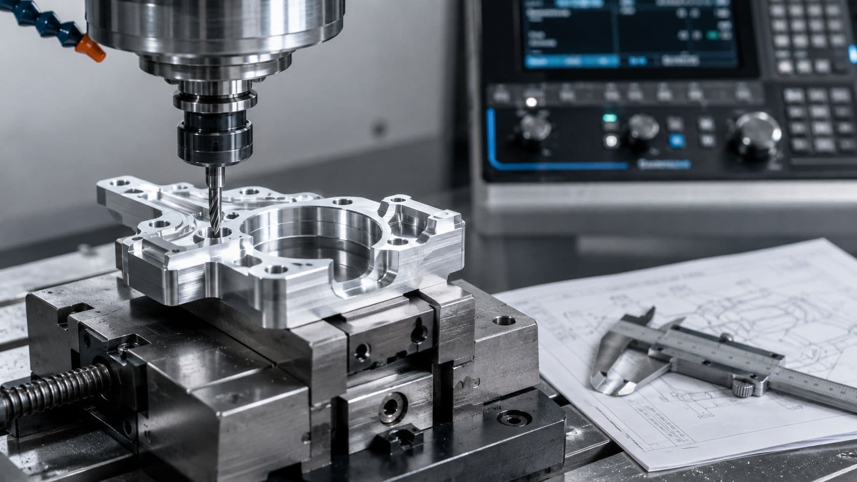
The popular advice says to buy the fastest quote and move on. That sounds efficient until the prototype arrives late because the shop had to buy stock, build a fixture, clear a finishing queue, and inspect the part after the spindle time was already done. In prototype machining services, spindle time is only one slice of the calendar, and the quote that looks slower on paper can still deliver sooner in the world.
That's why the right question isn't “Who promises the shortest turnaround?” It's “Who can control the hidden stack of setup, materials, finishing, and inspection for this part?” For early validation, that difference matters more than a flashy lead-time claim, because the prototype has to answer a design question, not just look finished.
Table of Contents
- Why Fastest Machining Is Not Always the Best Prototype
The hidden queue is usually the real schedule
Core Capabilities of Modern Prototype Machining Services- Match the machine to the geometry
Understanding Tolerance Tiers and Their True Cost- Hold the right dimensions, not every dimension
Design for Manufacturability Tips That Shorten Lead Times- The small geometry choices that save days
CNC Machining Versus Additive and Hybrid Prototyping- Choose based on the validation target
How to Choose the Right Prototype Machining Partner- Check the operating discipline, not just the quote
A Realistic Project Timeline From Quote to Delivery- A mid-complexity aluminum bracket is not a five-day story
Why Fastest Machining Is Not Always the Best Prototype
The fastest machining quote often wins the inbox and loses the schedule. A shop can cut metal quickly and still miss your launch gate if it has to wait on a special alloy, split the job across several setups, or send the part out for anodizing and final inspection. In practice, total lead time matters more than the raw machine cycle, especially for prototype machining services where the first part often has to move through several hands before you can approve it.
The hidden queue is usually the real schedule
A simple part made from a stocked aluminum alloy can move fast, but many prototypes are not simple. The part may need a fixture, a second setup for hidden features, a finish pass, and a measurement report before anyone signs off. The guide on custom CNC lead times makes the point bluntly, simple CNC prototypes can machine in 1 to 3 working days, but end-to-end delivery often stretches to 4 to 8 days once express freight is added, and complex parts can take 5 to 10 working days before shipment, with specialty materials sometimes adding 2 to 4 weeks (lead-time guide).
Practical rule: If the prototype is meant for a fit check, speed matters most. If it has to prove function, reserve time for inspection, finishing, and rework risk.
The prototype machining market itself reflects that shift from “quick sample” to “validated part.” Services for prototype machining were valued at USD 319 million in 2024 and are projected to reach USD 557 million by 2034, with an 8.3% CAGR over the forecast period (market benchmark). That growth lines up with what engineers already see on the floor, teams want functional parts earlier, not just pretty ones.

A smart buying decision starts with the part's job. If you only need an enclosure mockup or a form-fit check, chase the shortest path through stocked material and minimal finishing. If the prototype is being used to validate mating surfaces, sealing, stiffness, or assembly behavior, pick the shop that can hold the right tolerances and manage the handoffs without surprises.
Core Capabilities of Modern Prototype Machining Services
Prototype machining services are not one capability, they're a stack of machines and process choices. A good quote starts with the geometry, then maps that geometry to the least complicated machine that can still hold the features you care about. That sounds obvious, but many delays start when the CAD file is matched to the wrong level of capability.
Match the machine to the geometry
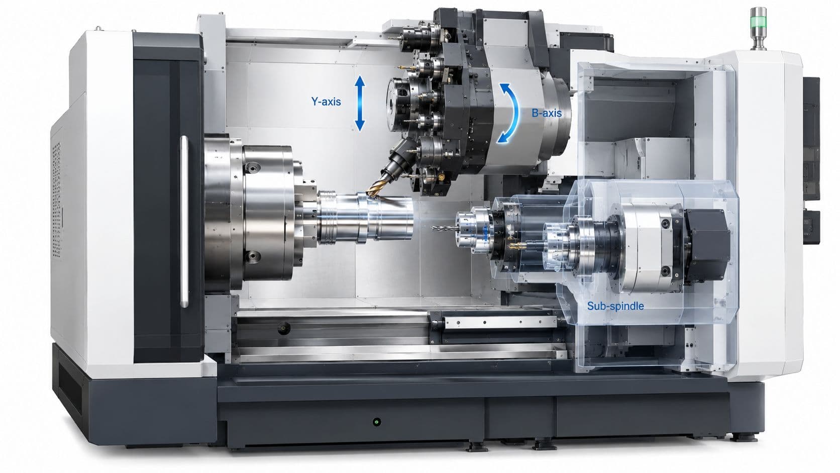
A 3-axis mill is the workhorse for brackets, plates, simple enclosures, and face-milled blocks. It's the right answer when the part can be reached from a few directions without clever fixturing. Move up to 4-axis indexed machining when you need cross-holes, radial patterns, or features on multiple faces without constantly re-clamping the part.
For parts with undercuts, compound curves, or awkward angular access, 5-axis machining earns its keep. That's the right territory for impellers, turbine-style geometry, medical shapes, and aerospace parts where tool access is the limiting factor rather than raw cutting power. On rotational parts such as shafts, fittings, and connector bodies, turning or mill-turn often beats a separate mill setup because the lathe can create concentric features in one controlled sequence.
A useful way to think about the process is simple, every extra setup introduces more chances for stack-up, distortion, and inspection delay. The more faces you can complete in one workholding strategy, the less the schedule gets chopped into fragments.
Materials change the machining conversation
Prototype machining services usually cover the same families of materials engineers already design around. That includes 6061-T6 and 7075 aluminum, 303 and 316L stainless steel, titanium Grade 5, and engineering plastics like Delrin, PEEK, Ultem, and PTFE. The material choice isn't just about strength, it also shapes chip control, tool wear, and whether the part behaves like the final product.
A prototype in the wrong material can answer the wrong question. If production is plastic, a metal sample may prove the dimensions and still mislead the team on fit feel, weight, and assembly behavior.
CNC capability tiers for prototyping
| Machine Type | Axes | Typical Part Geometries | Common Materials | Best For |
|---|---|---|---|---|
| 3-axis milling | 3 | Brackets, plates, housings, simple covers | Aluminum, stainless, plastics | Straightforward parts with easy access |
| 4-axis indexed machining | 4 | Cross-holes, radial features, multiple faces | Aluminum, stainless, engineering plastics | Parts that need more than one side without full 5-axis complexity |
| 5-axis simultaneous machining | 5 | Curved surfaces, compound angles, undercuts | Aluminum, titanium, stainless, high-performance plastics | Complex parts where tool access drives the design |
| CNC turning | 2+ | Shafts, sleeves, fittings, connector bodies | Metals and plastics | Round parts and concentric features |
| Mill-turn | Combined | Round parts with milled flats, grooves, holes | Metals and plastics | Parts that benefit from turning and milling in one setup |
For deeper vendor selection on process fit, the practical questions are similar to what's covered in the tight tolerance machining guide, which is useful when a prototype has critical interfaces that can't be left to guesswork.
Understanding Tolerance Tiers and Their True Cost
Tight tolerances are where prototype budgets go to get punctured. Engineers often over-specify every dimension because it feels safer, but not every feature needs the same control. A clean tolerance plan reserves the hardest work for the surfaces that matter.
Hold the right dimensions, not every dimension
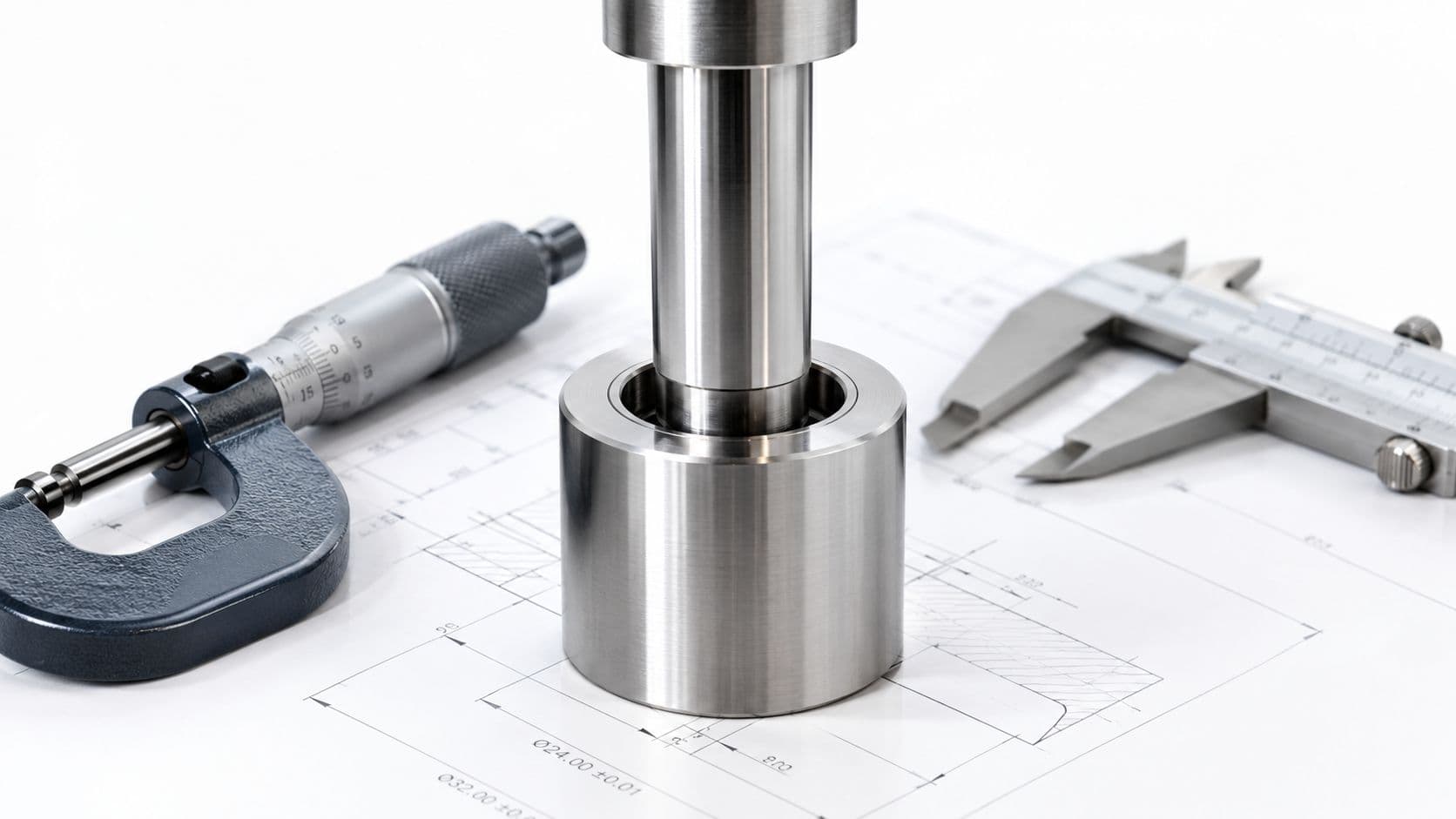
Most prototype shops can hold about ±0.005 in. (±0.13 mm) on general CNC milling and turning work, and tighter-feature work can reach about ±0.0001 in. on select critical features when geometry, fixturing, and metrology support it (prototype machining tolerance guidance). That range tells you something important, the cost and schedule rise nonlinearly as tolerances tighten because setup control, inspection burden, and scrap risk all climb together.
A practical tolerance strategy is to separate the drawing into functional and nonfunctional regions. Bearing bores, sealing surfaces, and mating interfaces deserve the tightest control. Cosmetic faces, noncritical wall sections, and reference surfaces usually do not.
Practical rule: Tighten the datums and interfaces, then let the rest of the part live at standard tolerance. That's usually the fastest way to protect both function and budget.
What the shop actually has to do
A tighter tolerance can trigger more than one machining pass. It can require better fixturing, extra temperature control, more in-process checks, and a longer inspection cycle at the end. If the part needs a CMM report or special gauge work, the machine may finish long before the job is ready to ship.
| Tolerance Tier | Range | Cost Multiplier | Inspection Method | Typical Applications |
|---|---|---|---|---|
| Standard | ±0.005 in. / ±0.125 mm | Baseline | Basic dimensional inspection | Brackets, housings, noncritical features |
| Precision | ±0.001 in. / ±0.025 mm | Higher than standard | CMM or focused gauging | Mating features, functional bores, threaded interfaces |
| Ultra-precision | ±0.0002 in. / ±0.005 mm | Highest | CMM, custom gauges, controlled environment | Critical interfaces, tight alignment features, regulated parts |
The lesson is simple. If a dimension doesn't change how the prototype works, don't force the shop to chase it like it does. If it does matter, call it out clearly and let the rest of the drawing stay sane.
Design for Manufacturability Tips That Shorten Lead Times
Most prototype delays are baked into the CAD file before the RFQ ever lands. Designers don't usually mean to create a slow part, they just don't always see which features force extra tooling, extra setups, or extra handwork. Good DFM turns those surprises into predictable machine time.
The small geometry choices that save days
Start with internal corners. A sharp inside corner often needs a smaller tool, which raises machining time and tool breakage risk. A standard end-mill radius is easier to produce and often avoids a secondary process later. Deep pockets do the same thing, they slow the cut, increase chip evacuation issues, and make the setup more delicate.
Wall thickness matters too. Thin walls can flex during machining and distort after unclamping, especially in plastics and tall aluminum parts. Keep thread specifications disciplined, because overcalling thread quality or adding unnecessary tapped depth invites extra operations that do not improve the prototype's usefulness.
The best DFM changes are usually the least dramatic. Put features on one side when you can. Reduce undercuts. Avoid cosmetic finish notes unless the prototype needs them. If the part needs bead blasting, anodizing, or passivation, say so clearly and expect the finish handoff to add time.
Use standards instead of exceptions
Standard radii, common tool diameters, and available stock sizes are the easiest ways to shorten the loop. When a part asks for custom tooling or awkward workholding, the job tends to grow in complexity faster than the drawing suggests. That's especially true when the prototype is small but has a lot of tiny, hard-to-reach details.
The DFM principle is straightforward, and it's the same one covered in the design for manufacturability guide, simplify what doesn't change the test result and leave the machining team room to work efficiently.

Sharp corners, deep pockets, and cosmetic overreach are the three most common ways a prototype turns into a longer job than anyone expected.
CNC Machining Versus Additive and Hybrid Prototyping
CNC machining and 3D printing solve different prototype risks. The right choice depends on what the part has to prove, because schedule, cost, and confidence change with the validation target. A form mockup can move fast through additive. A prototype that must behave like the final manufactured part usually needs machined stock and real tool access.
Choose based on the validation target
Additive manufacturing has a long history of speeding iteration. Charles W. Hull printed a teacup on the first stereolithography apparatus on 9 March 1983, later secured the patent for stereolithography in 1986, and Materialise introduced its NextDay 24-hour 3D printing service in 1997 (additive milestones). Those milestones helped establish a prototyping workflow built around quick shape checks and rapid design changes.
CNC stays stronger when the team needs tight mating surfaces, stable dimensions, or material behavior that is close to the final part. Additive is the better fit for internal channels, lattice structures, and shapes that would be awkward or costly to machine. Hybrid workflows sit between them. A printed near-net shape can be machined on the functional faces, so the team gets speed where it helps and accuracy where it matters.
The cost trade-off is often hidden in the handoffs. A printed part may look fast on paper, but post-processing, inspection, and cleanup can erase that advantage if the geometry is delicate or the finish has to be controlled. CNC has its own setup stack, yet it usually gives cleaner predictability once the tooling and workholding are sorted. The CNC vs. 3D printing guide walks through the same decision framework with additional examples.
The broader product prototyping market is projected to grow from USD 25.75 billion in 2026 to USD 44.19 billion by 2031, and functional testing is projected to grow faster than the overall market at 11.56% CAGR (product prototyping forecast). That trend points to more test-ready builds and more programs that mix processes instead of forcing one method to do everything.
Side-by-side trade-offs
| Criterion | CNC Machining | Metal/Polymer Additive | Hybrid (Print + Machine) |
|---|---|---|---|
| Dimensional tolerance stability | Strong on critical features | Depends on process and geometry | Strong on machined faces, mixed elsewhere |
| Surface cosmetic accuracy | Smooth and predictable | Often needs post-processing | Good where machined, mixed overall |
| Material property fidelity to production intent | High for machined stock materials | Depends on print material and orientation | High on machined interfaces, mixed body behavior |
| Lead-time behavior at low volumes | Efficient for functional parts | Fast for concept models and complex shapes | Useful when geometry is complex but interfaces matter |
| Pilot or bridge production readiness | Strong transition path | Often needs rework or process change | Good when the printed form is a precursor to machined validation |
The point is to match the process to the proof you need, not to favor one method by habit.
How to Choose the Right Prototype Machining Partner
A good prototype partner does more than cut chips. It pushes back on bad tolerances, flags risky geometry, and tells you where the schedule is really going to break. Shops that accept every drawing uncritically are usually the ones that cost the most later.
Check the operating discipline, not just the quote
Start with quality systems. Ask whether the shop works to ISO 9001 or AS9100, whether it has in-house CMM or optical inspection, and whether it can show material traceability and mill certs when needed. If the part is for a regulated or safety-sensitive program, those answers matter more than a discount.
Then ask about communication. You want a named project engineer, a clear DFM review loop, and sample inspection reports you can review before you commit. A vendor that responds quickly to technical questions usually saves more time than a vendor that says yes to everything.
The best partners also handle the logistics that get ignored in glossy brochures. Delicate prototypes need packaging that won't bruise edges or contaminate finishes. Offshore sourcing can work, but it adds variability that matters when the prototype is on a short runway.
A shop that asks hard questions during quoting is usually protecting your schedule, not slowing it down.
Red flags worth taking seriously
- Vague tolerance language: If the quote doesn't distinguish between general and critical features, the part may come back with the wrong priorities.
- No inspection evidence: If they won't share a sample report, you're being asked to trust the process without proof.
- No named owner: If nobody owns the job, nobody owns the delay when it happens.
- Weak DFM feedback: If the vendor never comments on geometry, expect avoidable rework.
- Promised speed with no detail: Fast claims mean little without a clear path for material, setup, finish, and inspection.
FIRMFG is one option in this space, it provides CNC machining for rapid prototyping alongside other processes like 3D printing, sheet metal, molding, and finishing, which can help when a program needs more than one fabrication path in the same development cycle. For teams comparing partners, that kind of process breadth can matter when the prototype is likely to evolve.

A Realistic Project Timeline From Quote to Delivery
A prototype project rarely moves in a straight line. The RFQ lands, the shop reviews the file, someone asks for a material substitution, the fixture gets revised, and the part still has to clear finishing and inspection before it leaves the building. That's why a “five-day turnaround” can become a much longer calendar even when the spindle work itself is short.
A mid-complexity aluminum bracket is not a five-day story
Take a bracket in aluminum with a tight bore tolerance and a bead-blast anodized finish. Day one is usually not machining, it's engineering review, clarifying the bore requirement, and checking whether stock material is available. If the material is not on the shelf, the procurement step can become the quiet schedule killer.
By day two or three, the shop may have the CAM path ready and the fixture in motion. If the bracket needs more than one setup, the work is split across operations so the part can stay stable while features are added. After that, the part often moves to deburring, bead blasting, anodizing, and inspection, all of which add handoffs that the quote often compresses into a single promise.
The practical timeline for this kind of job often looks closer to this:
- RFQ review and DFM clarification.
- Material confirmation and procurement.
- Fixture planning and CAM.
- Rough machining and critical feature machining.
- Finishing handoff.
- First-article inspection.
- Packing and shipping.
If the shop already stocks the material and keeps inspection in house, the job can move much faster. If it has to outsource finishing or wait for a special alloy, the calendar stretches. That's the hidden gap between machine time and delivery time.
How engineers compress the calendar
Pre-approve material alternatives when possible, especially for aluminum prototypes where several alloys may serve the same validation goal. Keep cosmetic requirements simple until after functional approval. Ask for parallel inspection on critical dimensions instead of waiting for a final pass to discover a problem.
The most effective move is often the simplest one, make the shop's job easier before the drawing is frozen. A clean STEP file, a clear tolerance scheme, and an honest finish requirement save more days than a rushed follow-up email ever will.
If you're planning a first prototype run, send the drawing with the fewest assumptions you can manage and ask for DFM feedback before you lock the schedule. Visit FIRMFG if you want a manufacturing partner that can review CNC prototype work alongside additive, finishing, and low-volume build options, then compare the process mix against your actual validation goal instead of chasing the shortest quote.