STL vs OBJ: The Practical 3D Printing Format Guide
Most advice about STL vs OBJ starts in the wrong place. It treats the choice like a feature checklist, then ignores the part that burns teams, the handoff, where a file gets exported, repaired, renamed, zipped, emailed, re-imported, and finally rejected for reasons nobody saw coming.
| Attribute | STL | OBJ |
|---|---|---|
| Geometry | Triangles only | Triangles, plus richer mesh structure |
| Normals | Face-based, minimal surface intelligence | Vertex normals and smoother shading support |
| UVs and textures | Not supported | Supported through companion material and texture files |
| Materials | Not supported in the standard form | Supported through material references |
| File layout | Usually a single file | Often a bundle of geometry, material, and texture files |
| Typical shop-floor use | Slicer-first printing | Review, rendering, scan context, textured assets |
The core question is simpler and harder. Which format protects the chain from failure points, and where does the chain need a newer container altogether?
Table of Contents
- Why STL vs OBJ Is the Wrong Question at the Handoff
- Where STL and OBJ Actually Came From
Two formats, two assumptions
Geometry, Normals, and What Each Format Preserves- What the printer sees versus what the artist sees
File Size and Triangle Density Tradeoffs- What those numbers mean on real jobs
The Hidden Risk of Multi-File OBJ Workflows- How the bundle breaks in practice
Export, Repair, and Slicer Behavior in Practice- Where the workflow actually breaks
Matching the Format to CNC and Prototyping Use Cases- Use-case decisions that hold up on the shop floor
When Neither STL nor OBJ Is the Right Answer- Why 3MF changes the conversation
Why STL vs OBJ Is the Wrong Question at the Handoff
An OBJ reaches the printer without its material file, texture map, or other sibling files. The geometry may still load, but the receiving tool can show missing references, incorrect appearance, or a part that requires manual repair before anyone can proceed. The result is a re-export, another transfer, and a handoff that fails despite the original model being valid.
That scenario exposes why OBJ wins on features is an incomplete conclusion. OBJ carries richer surface data, but those extra references create more dependencies. STL stores less and often moves through a slicer with fewer points of failure. On the shop floor, the useful question is which format survives export, renaming, transfer, repair, and slicing without demanding detective work from the next person.
STL remains practical because it delivers a triangulated surface in a form slicers generally understand immediately. Its limits are clear: it carries printable shape, not the broader visual or manufacturing context. OBJ can preserve more, but that advantage exists only when every tool and every handoff preserves the related files and interprets them consistently.
Practical rule: if the next person only needs printable geometry, extra metadata can become extra risk.
Choose the format by the handoff. Verify how the target slicer, CAD system, or review tool handles the file, including missing references, surface normals, units, and repair prompts. Confirm whether the recipient needs visual context beyond the part's shape, or only a watertight mesh ready for processing.
That decision also exposes when STL and OBJ are the wrong options. If materials, units, and build settings must travel with the model across departments, 3MF deserves evaluation before the team repeats a familiar export routine. A newer container may reduce the number of separate files and assumptions that can break between design, review, and production.
Where STL and OBJ Actually Came From
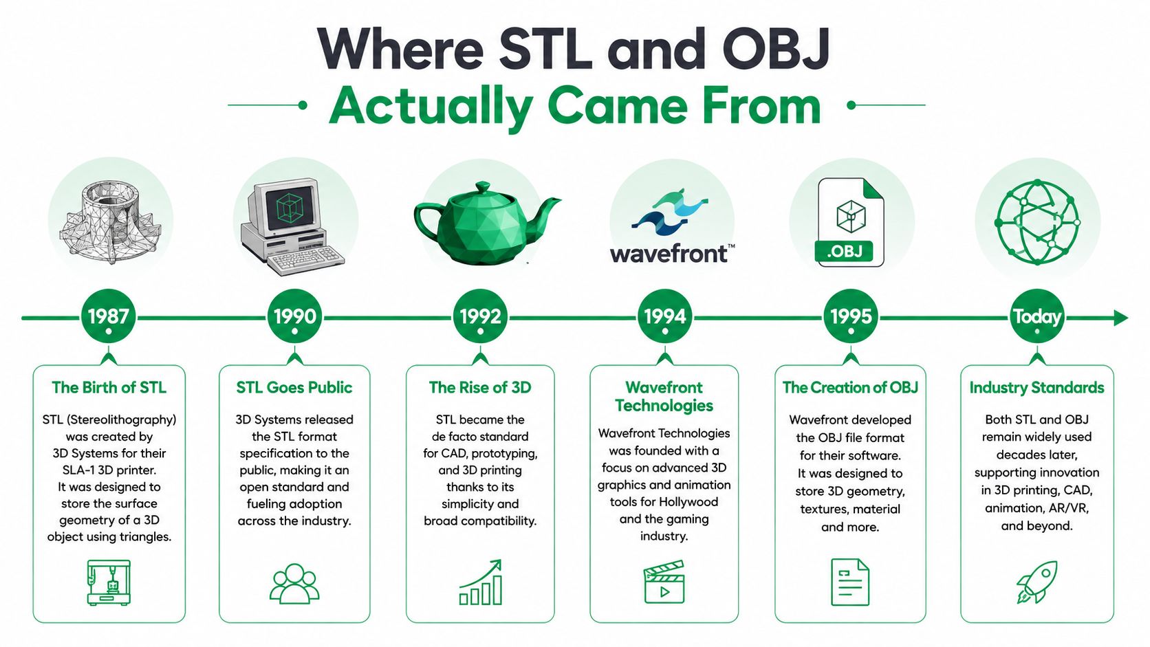
STL was built for 3D Systems' stereolithography machines in 1987. The Library of Congress describes it as a format published to translate CAD data for 3D printers Library of Congress digital format note. Its design starts with a clear production assumption: transfer the part's shape quickly as triangles to equipment that does not need presentation or scene context.
OBJ came from a different problem. Developed around the mid-1980s at Wavefront Technologies, it supported animation and graphics workflows that needed vertices, normals, texture coordinates, and material references CAD Interop OBJ format overview. OBJ was designed to move a viewable, editable asset between visual software, not to act as a self-contained printer job.
Two formats, two assumptions
STL treats the printable surface as the deliverable. OBJ treats the mesh and its associated surface information as part of the handoff. That distinction still affects failure risk: STL can usually travel as one file, while OBJ may depend on companion material and texture files that must keep their names and paths.
The origin also explains common software behavior. A slicer often opens an STL directly and presents it as a mesh ready for orientation or repair. CAD systems and modeling tools commonly expose OBJ export settings for visual assets, scans, or review files, where appearance matters alongside shape.
That history is also why teams should evaluate 3MF before standardizing either legacy format for a newer workflow. Its container approach can keep more job context together, reducing the separate assumptions that otherwise have to survive export, transfer, and import.
Geometry, Normals, and What Each Format Preserves
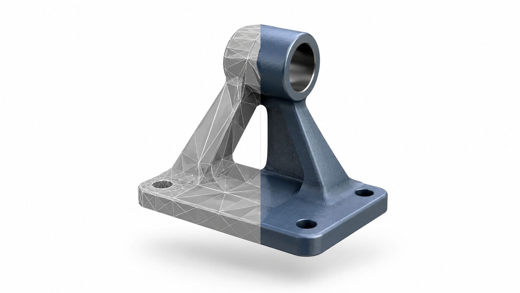
STL stores triangulated geometry and little else. OBJ stores the mesh plus surface context such as UV coordinates, vertex normals, and material references 3D AI Studio STL vs OBJ comparison. That difference sounds abstract until you open a curved surface and see whether the export preserved smooth shading or reduced it to faceted patches.
What the printer sees versus what the artist sees
STL treats every face as a triangle in a printable shell. It does not care about smoothing groups, texture mapping, or how the model looked in the source program. That simplicity is why it's so reliable for slicer-first work, but it also means any visual nuance gets discarded on export.
OBJ keeps more of the source intent intact. It can preserve geometry, normals, and texture references, which matters when a scan review, rendered preview, or color asset still needs to look like the original. The trade-off is that the same richness creates more places for a handoff to fail.
| Geometry and surface data preserved by each format | STL | OBJ |
|---|---|---|
| Triangulated geometry | Yes | Yes |
| Vertex normals | No | Yes |
| UV coordinates | No | Yes |
| Material references | No | Yes |
| Smoothing groups | No | Yes |
| Single-file simplicity | Yes | No, typically depends on companions |
The practical implication on curves and finishes
If you export a cylindrical or sculpted part too coarsely to STL, the slicer gets a faceted approximation. That's not a problem for every part, but it matters when cosmetic surfaces or scan comparisons need to stay faithful. OBJ helps preserve surface intelligence, which is useful for review and rendering, but that advantage disappears if the receiving tool ignores the extra data.
A mesh that looks better in the viewer isn't automatically a safer manufacturing file.
That's the distinction many teams miss. STL is a clean manufacturing envelope, while OBJ is a richer surface package. Pick the one that matches the next decision in the chain, not the one that merely contains more information.
File Size and Triangle Density Tradeoffs
File size becomes a manufacturing concern when models cross upload limits, versioning systems, or supplier handoffs. A direct comparison shows why the format label alone is not enough: binary STL measured 245,084 bytes for 14,700 triangles, while OBJ measured 230,569 bytes for positions and faces only, and 625,486 bytes when UVs and normals were included, with ASCII STL much larger at 1,527,844 bytes in that same comparison 3D Tool Wiki OBJ vs STL comparison.
What those numbers mean on real jobs
Binary STL is usually the leaner choice when the receiving system needs printable geometry and nothing else. Its compact triangle representation makes the file easier to archive, transfer, and load into a slicer. ASCII STL remains useful for inspection or simple text-based workflows, but its larger footprint makes it a poor choice when transfer stability matters.
Triangle density still deserves attention. A coarse mesh can produce visible faceting or reduce dimensional fidelity, while an unnecessarily dense mesh increases storage and transfer costs without improving the manufactured result. Set the density against the part's tolerance, surface requirements, and the receiving software's behavior rather than exporting at the highest available setting.
OBJ may start smaller than binary STL when it contains only positions and faces. Add UV coordinates, normals, materials, or related assets, and the package grows. That added size matters on large assemblies and in portals with upload caps. It also increases handoff exposure, because a receiving tool may use only the shell while ignoring the extra data.
Shop-floor rule: if the destination is a slicer or an archive that only needs triangles, binary STL is usually the leaner handoff.
For SLS and other additive workflows, keeping the mesh exchange predictable often matters more than preserving visual context. FIRMFG's SLS printing overview provides relevant process context. For new workflows, evaluate 3MF alongside STL and OBJ before standardizing. It may reduce the need to force manufacturing data through a format that was never designed for the entire handoff.
The Hidden Risk of Multi-File OBJ Workflows
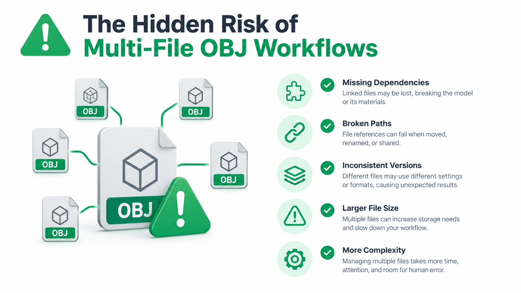
OBJ looks flexible because it can carry more context, but that context often lives in separate files. The geometry file points to an MTL file, and that material file often points to texture assets by relative path. Move the bundle without preserving structure, and the model may still open, but the visual intent is gone.
How the bundle breaks in practice
The failure modes are dull and common. Someone zips the wrong folder. Someone renames a directory. Someone emails the geometry without the companion material file. The slicer or viewer opens the mesh, then quietly drops the textures, or shows a plain default surface.
That's why OBJ can be fragile in ways STL isn't. STL is self-contained. If the file arrives, the printable surface arrives with it. OBJ can be more descriptive, but the description is distributed across multiple dependencies that have to stay aligned.
This matters even when the downstream tool nominally supports OBJ. Many slicers care more about the shell than the visual stack, so the extra files add risk without improving the print. The result is a format that looks richer in theory and behaves like a liability when handoff discipline is uneven.
The fix is not to ban OBJ. The fix is to know when its multi-file structure is a feature and when it is just one more thing that can get separated during transfer. If your team needs a checklist for packaging prototypes correctly, keep the process tight and review it against a simple prototype prep flow, not a loose assumptions chain. Prototype production checklist for shop-floor handoffs
What usually survives, what usually doesn't
- Geometry: usually survives if the file is intact.
- Textures and color: often disappear when a companion file is missing.
- Confidence in the handoff: drops fast when the package is moved between systems.
The safest interpretation is blunt. OBJ is fine when the receiver truly needs the richer surface context. If they don't, the extra structure only increases the number of ways the file can fail.
Export, Repair, and Slicer Behavior in Practice
STL exports are usually straightforward because most CAD systems know exactly what to do with them. The key variable is the triangulation quality, not the file format itself. In a clean export, the file reaches the slicer as a simple shell, which is why STL remains the default path for a lot of additive work.
Where the workflow actually breaks
Repair tools are where teams spend time they didn't budget. Non-watertight shells, inverted normals, and self-intersections show up after export, then get caught by tools such as MeshLab, Netfabb, or built-in slicer repair features. That repair step is common because a mesh that looks acceptable in CAD can still be invalid as manufacturing input.
OBJ can preserve more of the source mesh, but the extra detail doesn't guarantee better downstream behavior. Unit assumptions are a classic trap, because the format doesn't consistently protect scale the way a manufacturing team expects. Import the wrong interpretation, and a part that should be modest in size can land at the wrong scale inside another system.
Practical rule: if a file has to survive repair, slicing, and possible re-import, choose the format that leaves the fewest hidden assumptions on the table.
Additive versus CAM behavior
For additive workflows, STL is usually the calmer choice because slicers are built around triangulated shells. OBJ can still work, but it often adds no slicing value unless the model needs its surface context during review. In CAM environments, the picture gets stricter, because mesh data can be treated differently depending on the toolchain and the operator's expectations.
For CNC or mixed manufacturing pipelines, keep the manufacturing intent separate from the visualization intent whenever you can. If the job is headed toward toolpaths, the geometry needs to be unambiguous. If the job is headed toward presentation or scan review, OBJ can stay useful longer before conversion.
That's also where post-processing discipline matters. A file that passes export but fails later because someone didn't verify the surface or the scale has already cost time, even if the print eventually succeeds. Practical post-processing guidance for prototype parts
Matching the Format to CNC and Prototyping Use Cases
For CNC milling from a scanned prototype, STL is usually the safer starting point. CAM packages care about the mesh as geometry, not as a carrier for texture and normal data, so OBJ's extra baggage can just complicate the path to toolpaths. When the job is purely about cutting a shape, keep the file plain.
Use-case decisions that hold up on the shop floor
- FDM prototyping: choose STL when you want slicer predictability and the part only needs geometry.
- Color prints and figurines: choose OBJ when texture maps or surface appearance must survive the transfer.
- Resin printing: lean toward STL after mesh validation, because most slicers want a watertight triangle shell.
- Scan review and photogrammetry: use OBJ internally when vertex color or UV context helps compare surfaces.
- Release to manufacturing: convert to STL if the production toolchain only needs print-ready geometry.
The pattern is easy to miss if you only look at file features. Use OBJ when visual context matters before fabrication. Use STL when the manufacturing handoff needs the least ambiguity possible. That line is especially clear when a model comes from a scanner and has to be reviewed before it gets cleaned for production.
If the model still needs human judgment on the surface, keep the richer file a little longer. If the model is ready for a machine, strip it down.
For teams that want outside manufacturing support, FIRMFG accepts STL and OBJ uploads in its quoting flow, which makes it usable as one of the intake paths for prototype work. The file choice still matters, because the goal is not just to upload something, it's to hand over the least fragile version of the part for the process you need.
When Neither STL nor OBJ Is the Right Answer
STL and OBJ remain useful, but their weaknesses create handoff risk. STL carries geometry without dependable units, color, or metadata. OBJ can preserve richer surface information, yet its geometry, material, and texture files can separate during compression, email transfer, or archiving. A file that opens on the author's workstation may arrive incomplete or scaled incorrectly.

Why 3MF changes the conversation
3MF is a stronger candidate when the handoff needs more than triangles. It bundles units, material definitions, and build settings with the model in one package. That gives the receiving slicer more context than a bare STL and avoids the separate-file failure mode common to OBJ. It does not remove every compatibility problem, so test it in the slicer and printer workflow that will run the job.
For engineering review and CNC, STEP and IGES remain better upstream choices when parametric continuity and feature-level editing matter. They are not slicer-ready triangle meshes, but they preserve design intent before a manufacturing system receives a derived mesh.
A cleaner decision path
Pilot 3MF with the slicer your team uses if handoff corruption keeps causing rework. If review and traceability matter, retain the CAD-native model as long as possible. STL and OBJ remain reasonable for legacy equipment or quick geometry exchange, but familiarity alone is a poor selection rule.
Use STL or OBJ when the destination system already constrains the decision. For new production-adjacent handoffs, evaluate 3MF first when the workflow must retain manufacturing context.
FIRMFG supports CNC rapid prototyping, 3D printing, and DFM feedback through uploaded files. Visit FIRMFG to review how STL or OBJ intake can move from quote to part.