Wire EDM Aluminum Guide for Tolerances and Finish
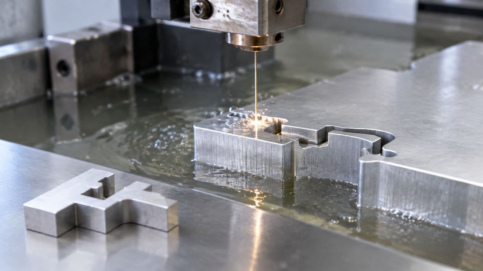
The usual advice on wire EDM aluminum starts and ends with conductivity: aluminum conducts electricity, so it's suitable. That's a qualification test, not a manufacturing specification. A wire-cut edge can meet its dimensional tolerance and still need additional work before it's suitable for fatigue loading, sealing, or cosmetic anodizing.
Yes, aluminum can be wire-EDMed. The useful decision is which feature deserves the process, what settings to test on a coupon, and which surface requirements must survive beyond dimensional inspection.
Table of Contents
Why a Spark Can Cut Aluminum- Separate thermal removal from wire control
What Pulse Flushing and Tension Change- Set the electrical window before chasing feed
Recast and Fatigue the Dimension Misses- Specify the surface's job
Aluminum Cut Problems and the Fix- Read the shape of the error
Choose Wire EDM, Milling, or Sheet Metal by Feature- Split the route around the controlling feature
Trial Settings and Results for Aluminum
Start with a parameter-development coupon, not a promise that a published setting will reproduce your drawing. Use the actual alloy, temper, section thickness, and intended wire, then separate productivity measurements from surface acceptance.
Aluminum wire EDM baselines from published trials
The following coupon baselines and statistical results are reported in the PLOS ONE aluminum wire EDM study; the statistical shares and prediction errors describe the published experiments, not guaranteed machine capability.
| Item | Published value | What it tells you | How to use it |
|---|---|---|---|
| 6061 recommended start | 50 µs on, 13 µs off, 4 A | A tested balance of energy and gap recovery | First coupon only, then retune for thickness |
| Pulse-on share of removal rate | 68.25% of the effect | On-time dominated productivity in that trial | Test on-time before chasing wire speed |
| Pulse-on share of roughness | 79.46% of the effect | Pulse duration strongly influenced crater formation | Reduce discharge energy on skim passes for Ra |
| Pulse-on share of kerf | 81.97% of the effect | Kerf and corner compensation move with energy | Compensate the measured kerf, not a catalog gap |
| Model error, removal rate | 1.69% | The regression tracked material-removal rate closely | Useful for planning, not a certified specification |
| Model error, roughness | 3.89% | Roughness required independent confirmation | Confirm Ra on the actual alloy and thickness |
| Model error, kerf | 0.88% | Kerf had the lowest reported prediction error | Still measure kerf with the job wire |
| Separate 6061 ANOVA | 13.33% for MRR, 16.25% for Ra | Pulse-on time and peak current were important contributors | Don't treat current as a free finish adjustment |
These results aren't interchangeable sensitivity coefficients. The separate investigations used their own experimental conditions, so don't combine their percentages into a universal ranking. The practical conclusion is narrower: electrical settings influence removal rate, roughness, and kerf differently, and you must measure each outcome.
Make the coupon a controlled comparison
Record the complete machine setup before cutting. Include pulse-on and pulse-off settings, current, voltage, wire type, wire-feed setting, tension, flushing arrangement, and programmed cutting feed. Save the machine's technology-table identifier too, because displayed settings aren't necessarily transferable between generators.
- Cut representative geometry. Include a straight wall, an internal corner, and the thinnest section that matters.
- Measure separate outcomes. Record cutting time or material-removal rate, arithmetic roughness Ra, and kerf width.
- Change one setting. Keep the remaining setup fixed so you can identify the cause of any improvement.
- Approve the finished condition. Evaluate the rough-and-skim sequence you intend to buy, not only the initial separation cut.
Kerf is the width removed by the wire and discharge gap. It determines the programmed offset, but a satisfactory straight-cut offset doesn't automatically establish corner accuracy.
Greater discharge energy generally produces larger erosion craters. A setting that makes the rough cut productive may therefore leave more work for finishing, even when the measured width looks correct.
Coupon rule: A published recipe is permission to run a controlled trial, not permission to release a production drawing.
Don't transfer the baseline to another thickness or machine without testing. The drawing should define the required result; the coupon establishes whether the proposed process can produce it consistently.
Why a Spark Can Cut Aluminum
Consider a thin aluminum insert with an enclosed, intricate opening. An end mill must physically enter the feature and resist cutting forces along its walls. A wire electrode instead travels through a prepared threading hole and follows the through-profile without pressing an edge against the material.
Think of a hot needle stitching a path through plate, but replace physical contact with controlled electrical discharges. The wire moves continuously, and each spark crosses a dielectric gap, concentrating heat in a small volume of the workpiece.
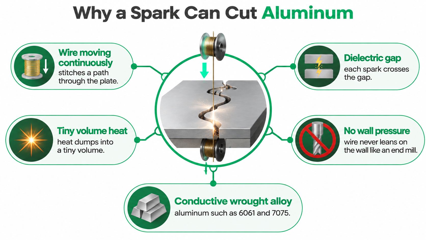
The process requires electrical conductivity, rather than conventional mechanical machinability. A 6061 aluminum experimental study describes material removal through repeated discharges and found, across eight combinations of pulse-on time and wire tension, that longer pulses increased material-removal rate while higher tension primarily improved stability, wire wear, and finish.
Separate thermal removal from wire control
The spark locally melts and vaporizes aluminum. The dielectric carries debris away so the next discharge can occur across a controlled gap. Conductivity makes the alloy eligible, but stable debris evacuation makes the cut repeatable.
The tension result matters because it prevents a common tuning mistake. Increasing tension isn't a substitute for selecting productive electrical settings. Its job is to keep the moving electrode sufficiently controlled to follow the intended path.
For the insert, that means assigning different purposes to different controls:
- Pulse duration establishes how aggressively the discharge removes material.
- Wire tension supports stable electrode behavior and the resulting wall quality.
- The dielectric system clears the gap rather than acting as conventional cutting lubricant.
No tool-to-wall contact doesn't mean the part is immune to movement. Clamping, flushing forces, and released material stresses still require sensible workholding, especially when the cut separates a delicate feature from supporting stock.
Choose geometry that benefits from the mechanism
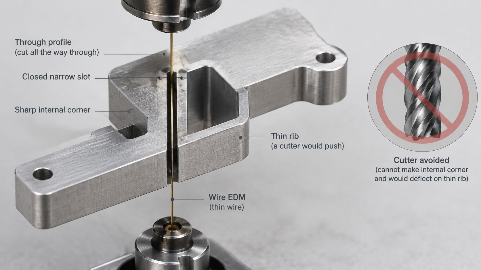
Wire EDM earns its place on intricate through-profiles, narrow slots, and thin features that are awkward to finish with a rotating cutter. An enclosed opening needs a threading route, and the wire must pass through the section, so it isn't a replacement for milling a blind pocket.
The design advantage is access without a rotating tool's cutting load. Use that advantage deliberately, rather than selecting wire EDM because the alloy can accept a spark.
What Pulse Flushing and Tension Change
Pulse-on time is the main energy-duration control, but a stable aluminum cut requires the rest of the setup to support it. Increasing removal demand without maintaining gap recovery, wire control, and debris evacuation can turn an apparently faster setting into a slower job with more corrections.
The aluminum process-optimization paper available through PubMed Central discusses feed, flushing, and dimensional accuracy, and reports independent aluminum 6060 experiments in which increasing wire-feed rate from 3 to 7 m/min increased average surface roughness. That's a result for those conditions, not a reason to confuse wire consumption speed with the table's cutting feed.
What each wire EDM control does to aluminum
| Control | If you raise it | Finish or accuracy risk | Planning rule |
|---|---|---|---|
| Pulse-on time | More melting and higher removal potential | Larger craters, wider kerf, rougher Ra | Reserve aggressive long-pulse settings for roughing |
| Pulse-off time | More time for gap recovery and debris clearance | Too little recovery destabilizes the gap | Allow enough recovery for the actual section |
| Peak current and voltage | Can increase discharge intensity or alter gap behavior | Aggressive settings can enlarge craters or disturb stability | Tune with on-time using the machine's technology guidance |
| Wire tension | Little direct removal-rate benefit | Insufficient tension permits wandering and wear | Set tension for stability within wire and machine limits |
| Wire-feed rate | Fresh wire enters the gap faster | Faster wire feed can worsen finish on some aluminum setups | Use the lowest feed that remains stable when Ra matters |
| Table feed | Higher productivity demand | Error grows if discharge and flushing cannot keep pace | Slow corners and finish passes |
| Flush pressure | Better debris removal when balanced | A one-sided jet can deflect the wire and produce taper | Match nozzle conditions before increasing pressure |
Set the electrical window before chasing feed
Pulse-off time isn't wasted time. It provides recovery between discharges, and shortening it beyond what the gap can tolerate can cause unstable sparking even when pulse-on time appears conservative.
Current and voltage also aren't interchangeable knobs. Peak current affects discharge intensity, while open-circuit voltage influences discharge initiation and gap behavior. Use the machine's aluminum technology guidance rather than assuming that raising either produces the same result.
Then establish a stable wire-feed setting. Wire-feed rate replenishes the electrode; table feed advances the cut through the workpiece. A setup sheet that labels both as feed leaves room for an expensive programming error.
Check the physical setup at difficult features
Balanced flushing matters more than a high pressure reading alone. Check nozzle position, stand-off, obstructions, and whether either jet loses support as the wire enters a slot or exits an edge.
For thin sections, verify actual tension and alignment rather than relying entirely on the stored setup. Program a controlled slowdown through internal corners, where the discharge conditions and wire path change together.
More flushing pressure is useful only if it clears the gap without pushing the electrode away from its intended path.
Record the working combination once the coupon passes. For repeat orders, preserving nozzle arrangement and wire condition is as important as saving the electrical program.
Recast and Fatigue the Dimension Misses
A passed dimension doesn't prove an acceptable EDM surface. Coordinate inspection can establish where the wall is, but it doesn't establish the condition of the material at that wall.
Every discharge melts a local crater, and some molten material solidifies again as a recast layer. The Wiley review of EDM surface integrity explains that recast thickness and cracking depend on material characteristics and discharge conditions, and identifies particle pull-out, pits, voids, and microcracks as concerns in reinforced aluminum.
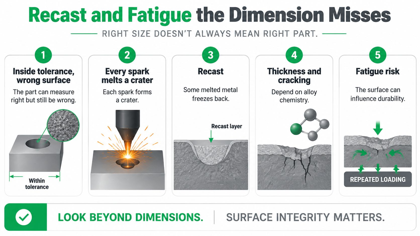
Aluminum's high thermal conductivity can moderate thermal damage compared with less conductive materials. It doesn't eliminate the need to qualify the edge. A surface that works on an unloaded fixture may be unacceptable at a cyclically loaded notch or a sealing interface.
Specify the surface's job
Distinguish the rough cut's purpose from the finished edge's acceptance criteria. Roughing separates material efficiently; finishing must establish the required profile and surface condition. If polishing or edge cleanup follows EDM, define what material removal is permitted so that finishing doesn't invalidate the dimension.
Use a short design-to-inspection checklist:
- Material identity. State alloy, temper, and any reinforcement rather than writing aluminum alone.
- Section geometry. Identify thickness changes and thin walls that need representative qualification.
- Service duty. Mark fatigue-sensitive, sealing, corrosion-sensitive, and cosmetic edges.
- Finishing route. Agree on the skim sequence and any permitted deburring or polishing.
- Acceptance evidence. Specify Ra, profile tolerance, taper allowance, edge condition, and any required surface-integrity examination.
For fatigue-critical hardware, discuss a representative sectioned coupon and metallographic examination with the responsible materials engineer. A roughness trace alone won't establish the absence of a problematic altered layer or microcracks.
Reinforced aluminum needs its own qualification
SiC- or graphite-reinforced aluminum is not just a more difficult version of wrought plate. The matrix and reinforcement can respond differently during erosion, leaving defects that a normal wrought-alloy coupon doesn't represent.
Even among conventional alloys, don't substitute a material designation casually. The design considerations in 6061 versus 2024 aluminum should be resolved before the manufacturing route is frozen.
For a noncritical prototype, ordinary dimensional inspection and an agreed edge finish may be sufficient. For a loaded, sealing, or appearance-critical feature, write the surface requirement before quoting. Otherwise, procurement may compare a rough-cut price against a qualified finished-edge price as though they describe the same part.
Aluminum Cut Problems and the Fix
A rough, cratered edge is a reason to investigate discharge conditions before rejecting the alloy. Start with the failed characteristic, identify a likely mechanism, and make a controlled correction rather than changing the entire technology table.
Experiments on 2017-T451 and 7075-T651 reported in the International Journal of Advanced Manufacturing Technology found that pulse-on and pulse-off times significantly affected arithmetic roughness, while surface inspection found no cracks under the tested conditions. That last qualification matters: an acceptable experimental surface isn't a blanket assurance for every alloy, thickness, or roughing regime.
Aluminum wire EDM symptoms and fixes
| What you see | Usual cause to investigate | Change to make |
|---|---|---|
| Rough cratered edge | Pulse-on too long for the finish goal | Shorten on-time, then evaluate a finishing skim |
| Unstable sparking or burns | Insufficient pulse-off time for debris clearance | Lengthen off-time before increasing feed |
| Tapered or bowed wall | Unbalanced flushing or inadequate wire control | Match the jets, then verify tension |
| Washed-out internal corner | Excessive programmed feed through the corner | Reduce corner feed and verify with a skim |
| Ra jumps on the finish pass | Cutting feed too aggressive for the finishing regime | Reduce finishing feed while holding other settings fixed |
| Blotchy anodize on an accurate feature | Recast or roughness may remain on the final edge | Qualify a skimmed or polished coupon before anodizing |
| Dimensional drift on a thin wall | Local thermal and flushing conditions changed | Test a representative thin coupon at lower energy |
Read the shape of the error
A uniformly rough wall suggests a different investigation from a smooth wall that leans. Inspect the crater pattern under magnification, then measure the profile at different heights through the section. Don't average away taper by reporting only a central measurement.
An internal corner that has lost material can't be repaired by tightening the title-block tolerance. Check the programmed slowdown, path compensation, and finishing allowance before cutting another part.
Troubleshooting discipline: Change the suspected cause, recut the same geometry, and keep the failed coupon beside the improved one.
Qualify the edge before the finishing tank
Treat visible anodizing differences as a diagnostic clue, not proof that EDM caused the defect. Compare a finished coupon with an untreated cut edge and review the preparation sequence before changing the entire machining route.
For an appearance-critical housing, coordinate the final edge preparation with aluminum anodizing requirements. If polishing is selected, protect the profile and corner geometry instead of blending the edge by eye.
Keep the inspection record tied to the finishing route. A coupon approved before anodizing doesn't establish that the final cosmetic surface is acceptable, and a visually uniform anodized edge doesn't independently prove fatigue suitability.
Choose Wire EDM, Milling, or Sheet Metal by Feature
Choose the process by feature, not by the part's alloy or drawing number. Wire EDM is valuable where access, slender geometry, or a precise through-profile defeats economical milling. It's usually a poor use of machine time for open pockets and straightforward bulk removal.
A mixed route often makes the most sense: mill the accessible stock, then wire only the feature that needs it. Flat panels and bent brackets deserve a sheet-metal review before anyone quotes them from solid plate.
When aluminum should be wired, milled, or cut as sheet
| Feature situation | Prefer | Why | Change the call if |
|---|---|---|---|
| Narrow slot, closed profile, or sharp internal corner | Wire EDM | No rotating-cutter load and access through a threading route | The slot is wide and open enough to mill |
| Thin rib that chatters under a tool | Wire EDM | The electrode doesn't mechanically cut against the wall | The rib is thick and the profile is simple |
| Open pockets and most of the stock | CNC milling | Cutting is generally more economical for bulk removal | A remaining window is inaccessible to a suitable cutter |
| Flat bracket or enclosure outline | Sheet metal | The outline and bends don't justify EDM | An internal precision profile requires secondary machining |
| Conventional wrought-alloy prototype | Mill plus wire only where needed | Each process handles the features it suits | Fatigue or anodizing requires additional finishing and inspection |
| SiC- or graphite-reinforced aluminum | Dedicated EDM trial | Reinforcement changes the surface-defect risks | No representative trial is planned, so qualification remains unresolved |
The wire's path still has geometric limits. Sharp internal corners aren't mathematically sharp: wire size and the discharge gap establish a finite radius. Confirm the permissible radius and threading access before treating the process as a solution.
Split the route around the controlling feature
For a 6061 electronics housing, keep the broad pocket milled. If a narrow enclosed through-slot can't accept a practical cutter, reserve that slot for wire EDM and make slot width the primary post-cut check. If the slot is blind rather than through, wire EDM isn't the appropriate route.
For a 7075 robotics link, a thin rib beside a precise internal opening may justify wiring the local profile after rough machining. Check rib taper through the section, not merely its width at the accessible face. If the rib is fatigue-sensitive, include its final surface condition in acceptance.
A 2024 aerospace bracket may need milling for open pockets and the outside form, with wire EDM limited to a precision window. Make the internal corner radius an explicit check, and let the responsible engineering specification determine the required surface-integrity verification.
These are feature-selection scenarios, not universal alloy recipes. The distinction is important: a familiar material designation doesn't establish that the proposed edge is qualified.
Quote the complete manufacturing route
For the milling portion, the planning considerations in CNC machining aluminum help separate accessible features from details that need another process. Include datum transfer and inspection access in that split, because moving the part between processes introduces setup work even when each individual operation is straightforward.
At FIRMFG, we offer wire EDM and machine aluminum alloys 6061, 7075, and 2024. For a useful route review, mark the candidate wire profiles on the drawing and identify whether the controlling check is slot width, taper, corner radius, or the finished anodized edge.
Procurement should compare quotes against the same pass sequence, surface requirements, and inspection deliverables. A cheaper rough cut isn't a cheaper equivalent if the assembly needs a qualified sealing or fatigue-sensitive edge.
FIRMFG offers wire EDM and aluminum CNC machining so you can evaluate a mill-plus-wire route for the features that need it. Visit FIRMFG, upload your CAD files with the candidate wire profiles marked, and include the alloy, thickness, finish, and inspection requirements. We provide a free CNC machining quote within 24 hours after CAD upload.